
NPOEEXT2X1G30 - Powerline Adapter Tripp Lite - Free user manual and instructions
Find the device manual for free NPOEEXT2X1G30 Tripp Lite in PDF.

| Product Type | 2-Port Gigabit PoE Extender |
| Brand | Tripp Lite |
| Model | NPOE-EXT-2X1G30 |
| Network Standards | IEEE 802.3, 802.3U, 802.3ab, 802.3at, 802.3bt, 802.3x |
| Ports | 1 PoE RJ45 input 10/100/1000 Mbps, 2 PoE RJ45 outputs 10/100/1000 Mbps |
| Power | Power over Ethernet (PoE) without external source |
| PD Input Power | 95 W max |
| PSE Output Power | 48-55 VDC, 30 W per port |
| Transmission Distance | Up to 100 m (328 ft) per segment, cascade up to 400 m (1312 ft) |
| Protection Rating | IP67 (waterproof), IK10 (impact resistant) |
| Dimensions | 150 x 73 x 44 mm (5.9 x 2.9 x 1.7 in) |
| Weight | 0.42 kg (0.93 lb) |
| Operating Temperature | -20 to 60 °C (-4 to 140 °F) |
| Storage Temperature | -40 to 80 °C (-40 to 176 °F) |
| Operating Humidity | 10 to 90% RH non-condensing |
| Surge Protection | Differential mode ±4 KV, common mode ±6 KV |
| MTBF | > 50,000 hours |
| LED Color | Green (link and activity) |
| Housing Material | Industrial grade, resistant to harsh environments |
| Installation | Plug-and-play, no configuration required |
| Warranty | 3-year limited |
| Package Contents | Extender, wrench, 3 waterproof connectors, quick start guide |
| Recommended Cable | Cat5e/6 UTP, max length 100 m |
Frequently Asked Questions - NPOEEXT2X1G30 Tripp Lite
User questions about NPOEEXT2X1G30 Tripp Lite
0 question about this device. Answer the ones you know or ask your own.
Ask a new question about this device
Download the instructions for your Powerline Adapter in PDF format for free! Find your manual NPOEEXT2X1G30 - Tripp Lite and take your electronic device back in hand. On this page are published all the documents necessary for the use of your device. NPOEEXT2X1G30 by Tripp Lite.
USER MANUAL NPOEEXT2X1G30 Tripp Lite
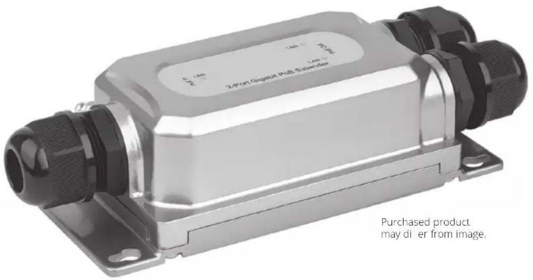
2-Port Gigabit PoE Extender/Repeater Waterproof, Hardened and Tamper-Proof
Model: NPOE-EXT-2X1G30
Español 12
Français 23
Deutsch 34
Italiano 45
Package Includes
• NPOE-EXT-2X1G30 2-Port Gigabit PoE Extender
- Wrench
• (x3) Waterproof Connectors
- Quick Start Guide
Product Features
• Supports Power over Ethernet so no external power supply is needed
• Supports true 10/100/1000 Mbps data transmission and PoE power supply distance up to 330 ft. (100 m)
• Includes one RJ45 95W PD input
- Two output ports have Power Sourcing Equipment (PSE) function, with each port supporting up to 30W
- Industrial-quality housing handles harsh environmental conditions with high stability and reliability
• IP67 waterproof rating
• IK10 impact protection rating against tampering and vandalism
- Complies with IEEE 802.3, 802.3u, 802.3ab, 802.3at, 802.3bt and 802.3x standards
- Unit supports plug-and-play operation with no additional configuration needed
Hardware Description
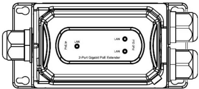
Front Panel
The front panel includes the PSE output port, input port and LED indicator.
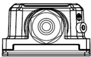
Left Panel
The left panel includes the input port (PoE In) and grounding column with standard network Cat5e cable (line diameter 5.5 mm).
natural_image
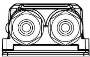
Technical line drawing of a mechanical housing or bearing component (no text or symbols)Right Panel
The right panel includes the output port (PoE Out), to be used with a standard network Cat5e cable.
natural_image
Technical line drawing of a mechanical component with two circular components mounted on a base (no text or symbols)Installation
Carefully read and follow all instructions to avoid device damage and security threats that could result from incorrect installation.
- The nuts of the waterproof joint should be tightened fully to the joint threads and fit level to the hexagon plane to prevent water from damaging your equipment
• To avoid damage, do not place the unit on an unstable surface
• Make sure the operating voltage is the same one labeled on the unit
• To avoid the risk of electrical shocks, do not open the chassis while the unit is operating or when electrical hazards are present
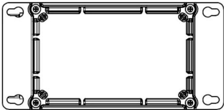
Desktop Installation
To install the unit on a desktop, place the bottom side (shown below) of the unit on a stable, solid surface.
natural_image
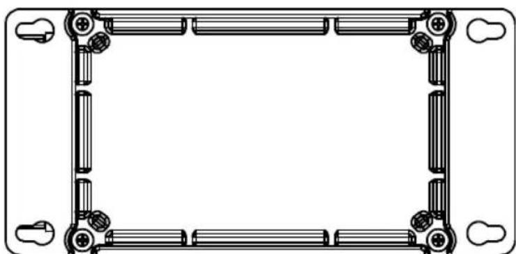
Pure technical line drawing of a rectangular frame with bolt holes and mounting points (no text or symbols)Wall-Mounted Installation
- Fix four screws (not included) on the wall and turn the unit upside down.
- Align the four fixing holes of the unit as shown below and mount the unit on the screws.
natural_image
Pure mechanical bracket diagram without any text, numbers, or symbolsInstallation
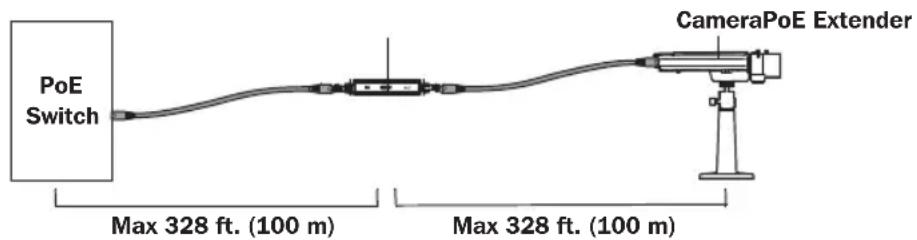
Single Extender Installation
Note: Prior to connecting the RJ45 cable to input/output ports, install the included cable glands onto the cable. Refer to Cable Wire and Crimp Steps below.
- Using a Cat5e/6 cable (up to 328 ft. / 100 m long), connect your powered source device (such as a PoE switch) into the "IN" port on the unit.
- Using another Cat5e/6 cable (up to 328 ft. / 100 m long), connect your remote PoE powered device (PD), such as a VoIP or IP surveillance camera, into the "OUT" port on the unit.
Notes:
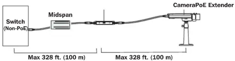
- Your PoE source must meet or exceed IEEE 802.3at / 802.3af standards.
- When power is required, the power source (e.g. midspan or PoE injector) must be installed between the Ethernet switch (non-PoE source) and the first NPOE-EXT-2X1G30 extender.
- If you are installing an injector and a splitter, they each need to support 60 to 90W.
Single Extender Installation Diagram
Single Extender Installation with Midspan Diagram
Installation
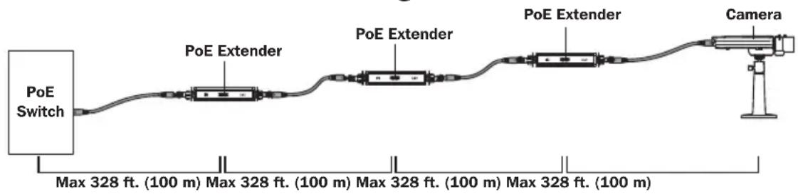
Multiple Extender Installation
Notes:
- You may only cascade three PoE extender units up to 1312 ft. (400 m) in a single installation.
- Prior to connecting the RJ45 cable to input/output ports, install the included cable glands onto the cable. Refer to Cable Wire and Crimp Steps below.
- Using a Cat5e/6 cable (up to 328 ft. / 100 m long), connect your powered source device (such as a PoE switch) into the "IN" port on the unit.
- Using another Cat5e/6 cable (up to 328 ft. / 100 m long), connect the "OUT" port of the first extender to the "IN" port of the second extender.
- Repeat Step 2 up to two more times for each additional PoE extender you add, or connect your remote PoE powered device (PD) to the "OUT" port of the second PoE extender.
Notes:
- The third PoE extender will only supply IEEE 802.3af up to 7W.
- Your PoE source must meet or exceed IEEE 802.3at standards.
Multi-Extender Installation Diagram
flowchart
graph LR
    A["PoE Switch"] --> B["PoE Extender"]
    B --> C["PoE Extender"]
    C --> D["PoE Extender"]
    D --> E["Camera"]
    style A fill:#f9f,stroke:#333
    style E fill:#ccf,stroke:#333
    note1["Max 328 ft. (100 m) Max 328 ft. (100 m) Max 328 ft. (100 m) Max 328 ft. (100 m)"] below A
    note2["100 m"]
    note3["100 m"]
    note4["100 m"]
    note5["100 m"]
    note6["100 m"]
    note7["100 m"]
    note8["100 m"]
    note9["100 m"]
    note10["100 m"]
    note11["100 m"]
    note12["100 m"]
    note13["100 m"]
    note14["100 m"]
    note15["100 m"]
    note16["100 m"]
    note17["100 m"]
    note18["100 m"]
    note19["100 m"]
    note20["100 m"]
    note21["100 m"]
    note22["100 m"]
    note23["100 m"]
    note24["100 m"]
    note25["100 m"]
    note26["100 m"]
    note27["100 m"]
    note28["100 m"]
    note29["100 m"]
    note30["100 m"]
    note31["100 m"]
    note32["100 m"]
    note33["100 m"]
    note34["100 m"]
    note35["100 m"]
    note36["100 m"]
    note37["100 m"]
    note38["100 m"]
    note39["100 m"]
    note40["100 m"]
    note41["100 m"]
    note42["100 m"]
    note43["100 m"]
    note44["100 m"]
    note45["100 m"]
    note46["100 m"]
    note47["100 m"]
    note48["100 m"]
    note49["100 m"]
    note50["100 m"]
    note51["100 m"]
    note52["100 m"]
    note53["100 m"]
    note54["100 m"]
    note55["100 m"]
    note56["100 m"]
    note57["100 m"]
    note58["100 m"]
    note59["100 m"]
    note60["100 m"]
    note61["100 m"]
    note62["100 m"]
    note63["100 m"]
    note64["100 m"]
    note65["100 m"]
    note66["100 m"]
    note67["100 m"]
    note68["100 m"]
    note69["100 m"]
    note70["100 m"]
    note71["100 m"]
    note72["100 m"]
    note73["100 m"]
    note74["100 m"]
    note75["100 m"]
    note76["100 m"]
    note77["100 m"]
    note78["100 m"]
    note79["100 m"]
    note80["100 m"]
    note81["100 m"]
    note82["100 m"]
    note83["100 m"]
    note84["100 m"]
    note85["100 m"]
    note86["100 m"]
    note87["100 m"]
    note88["100 m"]
    note89["100 m"]
    note90["100 m"]
    note91["100 m"]
    note92["100 m"]
    note93["100 m"]
    note94["100 m"]
    note95["100 m"]
    note96["100 m"]
    note97["100 m"]
    note98["100 m"]
    note99["1"]
Installation
Cable Wire and Crimp Steps
Installing Cable Gland with RJ45 UTP Cable
Step 1: Disassemble the cable gland as shown below:
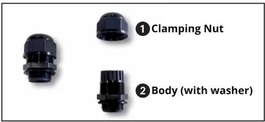
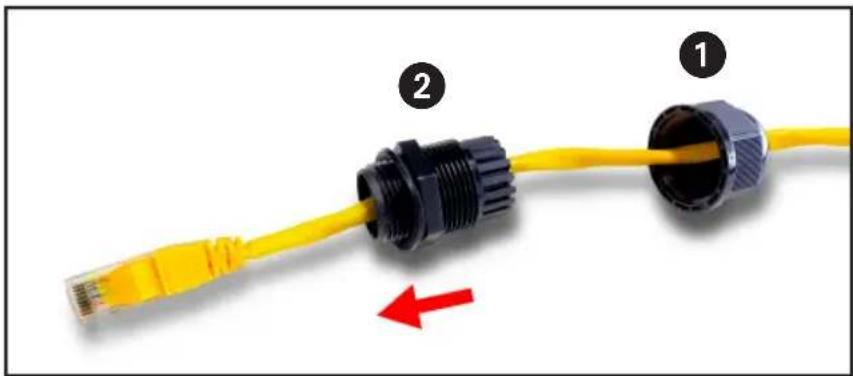
Step 2: Slip the Ethernet cable through the clamping nut and gland body. Tighten the clamping nut and the body to make the two parts into one complete cable gland.
natural_image
Yellow and black connector with labeled parts (1, 2) and a red arrow indicating direction (no text or symbols on the connectors themselves)Installation
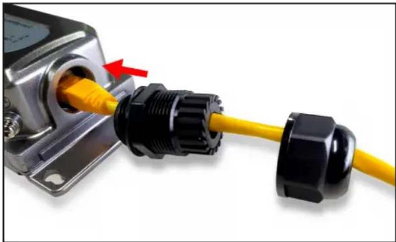
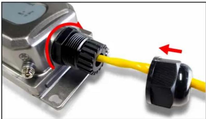
Connecting Waterproof Cable Kit to the Outdoor PoE Extender
Step 1: Insert the RJ45 connector into the connector of the PoE++ In Port.
natural_image
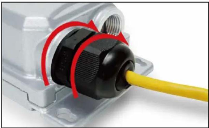
Close-up of a black and yellow electrical connector with a red arrow pointing to the cable (no text or symbols visible)Step 2: Turn clockwise to tighten the gland body with the Outdoor PoE Extender.
Step 3: Attach the clamping nut to the cable gland to complete the cable assembly.
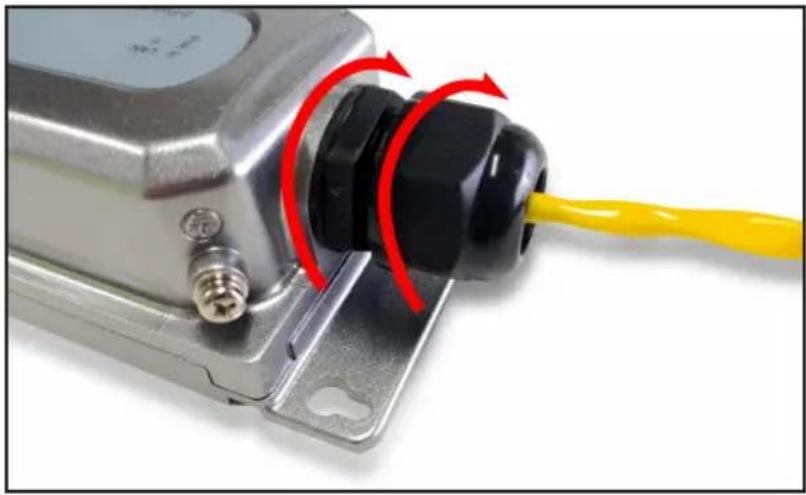
natural_image
Close-up of a metallic electrical connector with black plastic connectors and a yellow cable, showing red directional arrows (no text or symbols)Installation

natural_image
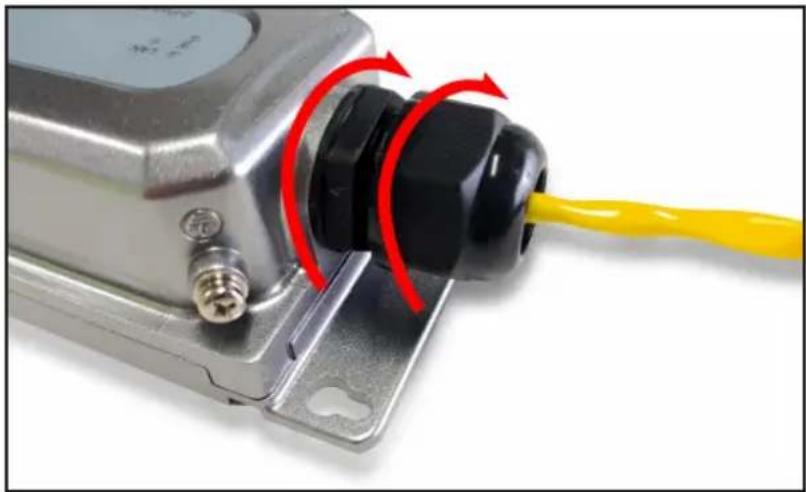
Close-up of a metallic electrical connector with a yellow cable inserted, showing red motion arrows (no text or symbols)Step 4: RepeatSteps 1 to 3 for two PoE+ Out Ports
natural_image
Close-up of a black plastic electrical plug with a yellow cable inserted, showing red curved arrows indicating motion (no text or symbols)Specifications
| Model | NPOE-EXT-2X1G30 |
| Standard | IEEE802.3, IEEE802.3u, IEEE802.3ab, IEEE802.3x, IEEE80 2.3af, IEEE802.3at, IEEE802.3bt |
| Ports | PoE In Port: 1 x 10/100/1000 Mbps RJ45PoE Out Port: 2 x 10/100/1000 Mbps RJ45 |
| Network Media (Cable) | 10BASE - T: UTP category 3, 4, 5 cable (≤100m)100BASE -TX: UTP category 5, 5e cable (≤100m)1000BASE -TX: UTP category 5e cable (≤100m) |
| LED Color | Green |
| LED Functions | Off: No device is connected to the corresponding portIlluminated: Indicates the link through that port is successfully established at 10/100/1000Mbps.Blinking: Transmitting data and power |
| Dimensions | 5.9 x 2.9 x 1.7 in. (150 x 73 x 44 mm) |
| Weight | 0.93 lbs. (0.42 kg) |
| PoE Ports | 2 |
| Power Supply | Power over Ethernet (PoE) |
| PD Port Input | 95W Max |
| PoE Power Output | 48-55V DC Max 30W per port |
| Operating Temperature Range | -4° to 140°F (-20° to 60°C) |
| Storage Temperature Range | -40° to 176°F (-40° to 80°C) |
| Operating Humidity Range | 10 to 90% RH, non-condensing |
| Storage Humidity Range | 5 to 90% RH, non-condensing |
| Surge Protection | Differential Mode: ± 4KVCommon Mode: ± 6KV |
| MTBF | >50,000 hours |
| Electrostatic Standard | Contact: 6KVAir: 8KV |
| Weather Rating | IP67 |
| Impact Protection Rating | IK10 |
Warranty
3-Year Limited Warranty
We warrant our products to be free from defects in materials and workmanship for a period of three (3) years from the date of initial purchase. Our obligation under this warranty is limited to repairing or replacing (at its sole option) any such defective products. Visit Tripplite.Eaton.com/support/product-returns before sending any equipment back for repair. This warranty does not apply to equipment which has been damaged by accident, negligence or misapplication or has been altered or modified in any way.
EXCEPT AS PROVIDED HEREIN, WE MAKE NO WARRANTIES, EXPRESS OR IMPLIED, INCLUDING WARRANTIES OF MERCHANTABILITY AND FITNESS FOR A PARTICULAR PURPOSE. Some states do not permit limitation or exclusion of implied warranties; therefore, the aforesaid limitation(s) or exclusion(s) may not apply to the purchaser.
EXCEPT AS PROVIDED ABOVE, IN NO EVENT WILL WE BE LIABLE FOR DIRECT, INDIRECT, SPECIAL, INCIDENTAL OR CONSEQUENTIAL DAMAGES ARISING OUT OF THE USE OF THIS PRODUCT, EVEN IF ADVISED OF THE POSSIBILITY OF SUCH DAMAGE. Specifically, we are not liable for any costs, such as lost profits or revenue, loss of equipment, loss of use of equipment, loss of software, loss of data, costs of substitutes, claims by third parties, or otherwise.
FCC Notice, Class B
This device complies with part 15 of the FCC Rules. Operation is subject to the following two conditions: (1) This device may not cause harmful interference, and (2) this device must accept any interference received, including interference that may cause undesired operation.
Note: This equipment has been tested and found to comply with the limits for a Class B digital device, pursuant to part 15 of the FCC Rules. These limits are designed to provide reasonable protection against harmful interference in a residential installation. This equipment generates, uses and can radiate radio frequency energy and, if not installed and used in accordance with the instructions, may cause harmful interference to radio communications. However, there is no guarantee that interference will not occur in a particular installation. If this equipment does cause harmful interference to radio or television reception, which can be determined by turning the equipment off and on, the user is encouraged to try to correct the interference by one or more of the following measures:
• Reorient or relocate the receiving antenna.
- Increase the separation between the equipment and receiver.
- Connect the equipment into an outlet on a circuit different from that to which the receiver is connected.
- Consult the dealer or an experienced radio/TV technician for help.
Any changes or modifications to this equipment not expressly approved by Eaton could void the user's authority to operate this equipment.
WEEE Compliance Information for Customers and Recyclers (European Union)

Under the Waste Electrical and Electronic Equipment (WEEE) Directive and implementing regulations, when customers buy new electrical and electronic equipment from Eaton, they are entitled to:
- Send old equipment for recycling on a one-for-one, like-for-like basis (this varies depending on the country)
- Send the new equipment back for recycling when this ultimately becomes waste
Use of this equipment in life support applications where failure of this equipment can reasonably be expected to cause the failure of the life support equipment or to significantly affect its safety or effectiveness is not recommended.
Eaton has a policy of continuous improvement. Specifications are subject to change without notice. Photos and illustrations may differ slightly from actual products.

Powering Business Worldwide
Eaton
1000 Eaton Boulevard
Cleveland, OH 44122
United States
Eaton.com
© 2024 Eaton
All Rights Reserved
Publication No. 23-10-127 / 93-3F48_RevB
March 2024
Eaton is a registered trademark.
All trademarks are property of their respective owners.
Extensor/Repetidor PoE Gigabit de 2 puertos
natural_image
Technical line drawing of a mechanical component with no visible text or symbolsPanel Derecho
natural_image
Technical line drawing of a mechanical component with two circular components mounted on a base (no text or symbols)Instalación
natural_image
Pure technical line drawing of a rectangular frame with bolt holes and mounting points (no text or symbols)natural_image
Pure technical line drawing of a rectangular frame with bolt holes and mounting points (no text or symbols)Instalación
natural_image
Yellow and black connector with labeled parts (1, 2) and a red arrow indicating direction (no text or symbols on the connectors themselves)Instalación
natural_image
Close-up of a black and yellow electrical connector with a red arrow pointing to the cable (no text or symbols visible)natural_image
Close-up of a metallic electrical connector with black plastic connectors and a yellow cable, showing red directional arrows (no text or symbols)Instalación
natural_image
Close-up of a metallic electrical connector with a yellow cable inserted, showing red motion arrows (no text or symbols)natural_image
Close-up of a black plastic electrical connector with a yellow cable inserted, showing red curved arrows indicating motion (no text or symbols)Especificaciones
natural_image
Technical line drawing of a mechanical housing or bearing component (no text or symbols)Panneau droit
natural_image
Technical line drawing of a mechanical component with two circular components mounted on a base (no text or symbols)Installation
natural_image
Pure technical line drawing of a rectangular frame with bolt holes and mounting points (no text or symbols)Montage mural
natural_image
Pure technical line drawing of a rectangular frame with bolt holes and mounting points (no text or symbols)Installation
natural_image
Close-up of a yellow and black USB cable with connector, showing pin numbering and a red arrow indicating compression (no text or symbols)Installation
natural_image
Close-up of a black and yellow electrical connector with a red arrow pointing to the cable (no text or symbols visible)natural_image
Close-up of a metallic electrical connector with black plastic connectors and a yellow cable, showing red directional arrows (no text or symbols)Installation
natural_image
Close-up of a metallic electrical connector with a yellow cable inserted, showing red motion arrows (no text or symbols)natural_image
Close-up of a black plastic electrical connector with a yellow cable inserted, showing red curved arrows indicating connection (no text or symbols visible)Caractéristiques
natural_image
Technical line drawing of a mechanical housing or enclosure component (no text or symbols)Rechtes Bedienfeld
natural_image
Technical line drawing of a mechanical component with two circular components mounted on a base (no text or symbols)Installation
natural_image
Pure technical line drawing of a rectangular frame with bolt holes and mounting points (no text or symbols)natural_image
Pure mechanical bracket diagram without any text, numbers, or symbolsInstallation
natural_image
Yellow and black connector with labeled parts (1, 2) and a red arrow indicating direction (no text or symbols beyond labels)Installation
natural_image
Close-up of a yellow cable connector with black plastic connectors, showing internal wiring and a red arrow indicating direction (no text or symbols)natural_image
Close-up of a metallic electrical connector with black plastic connectors and a yellow cable, showing red directional arrows (no text or symbols)Installation

natural_image
Close-up of a metallic electrical connector with a yellow cable inserted, showing red motion arrows (no text or symbols)natural_image
Close-up of a black plastic electrical plug with a yellow cable inserted, showing red curved arrows indicating motion (no text or symbols)Technische Daten
natural_image
Technical line drawing of a mechanical component with no visible text or symbolsPannello destro
natural_image
Technical line drawing of a mechanical component with two circular components mounted on a base (no text or symbols)Installazione
natural_image
Pure technical line drawing of a rectangular frame with bolt holes and mounting points (no text or symbols)natural_image
Pure mechanical bracket diagram without any text, numbers, or symbolsInstallazione
natural_image
Yellow and black connector with labeled parts (1, 2) and a red arrow indicating direction (no text or symbols on the connectors themselves)Installazione
natural_image
Close-up of a black and yellow electrical connector with a red arrow pointing to the cable (no text or symbols visible)natural_image
Close-up of a metallic electrical connector with black plastic connectors and a yellow cable, showing red directional arrows (no text or symbols)Installazione

natural_image
Close-up of a metallic electrical connector with a yellow cable inserted, showing red motion arrows (no text or symbols)natural_image
Close-up of a black plastic electrical plug with a yellow cable inserted, showing red curved arrows indicating motion (no text or symbols)Specifiche
- 2-Port Gigabit PoE Extender/Repeater Waterproof, Hardened and Tamper-Proof
- Package Includes
- Product Features
- Hardware Description
- Front Panel
- Left Panel
- Right Panel
- Installation
- Desktop Installation
- Wall-Mounted Installation
- Single Extender Installation
- Notes:
- Multiple Extender Installation
- Cable Wire and Crimp Steps
- Installing Cable Gland with RJ45 UTP Cable
- Connecting Waterproof Cable Kit to the Outdoor PoE Extender
- Warranty
- 3-Year Limited Warranty
- FCC Notice, Class B
- WEEE Compliance Information for Customers and Recyclers (European Union)
- Eaton
- Extensor/Repetidor PoE Gigabit de 2 puertos
- Panel Derecho
- Instalación
- Panneau droit
- Montage mural
- Rechtes Bedienfeld
- Technische Daten
- Pannello destro
- Installazione
Brand : Tripp Lite
Model : NPOEEXT2X1G30
Category : Powerline Adapter