
ZAF 250 Vario - Milling machine Mafell - Free user manual and instructions
Find the device manual for free ZAF 250 Vario Mafell in PDF.
| Product Type | Tenoning Machine / Wood Milling Machine |
| Brand | Mafell |
| Model | ZAF 250 Vario |
| Dimensions (L x W x H) | 1400 x 1400 x 1450 mm (machine only) Support table: 350 x 3000 x 900 mm |
| Weight | Machine: 380 kg Support table: 83 kg |
| Power Supply | Three-phase 400 V, 50 Hz, 16 A (CEE plug) Power consumption: 6000 W Output power: 4500 W |
| Rotation Speed | 6670 rpm at no load 6260 rpm under load |
| Feed Speed | 0.9 - 2.2 m/min (adjustable by 50%) |
| Maximum Workpiece Dimensions | Straight tenons: 500 x 250 mm Angled tenons (max 60°): 220 x 250 mm Flush trimming: 340 x 250 mm |
| Maximum Tenon Length | 110 mm |
| Maximum Flush Trimming Depth | 80 mm |
| Tool | Shaping head diam. 100 mm, shaping ring diam. 165 mm Cutting width: 110 mm Carbide reversible plates (3 times reversible) |
| Main Functions | Shaping straight tenons, angled (0-60°), vertical tenons Flush trimming Simultaneous chamfering Manual and automatic mode |
| Safety Devices | Automatic protective curtain, safety limit switch, motor brake (stop < 3 s), emergency stop, adjustment mode, laser class 2M |
| Noise Emissions | Sound power level: 108 dB(A) Emission at workstation: 93-94 dB(A) Wear hearing protection |
| Dust Extraction Connection | 2 sleeves diam. 100 mm Negative pressure: 258 Pa |
| Maintenance and Cleaning | Regular cleaning with vacuum cleaner Resin removal with petroleum or detergent Lubricate spindles with grease ref. 049040 |
| Spare Parts | Available at www.mafell.com Use original Mafell parts |
| Special Accessories | Extraction kit ref. 202320 |
| General Information | Manufacturer: Mafell AG, Germany Instruction manual included (70 pages) CE declaration of conformity |
Frequently Asked Questions - ZAF 250 Vario Mafell
User questions about ZAF 250 Vario Mafell
0 question about this device. Answer the ones you know or ask your own.
Ask a new question about this device
Download the instructions for your Milling machine in PDF format for free! Find your manual ZAF 250 Vario - Mafell and take your electronic device back in hand. On this page are published all the documents necessary for the use of your device. ZAF 250 Vario by Mafell.
USER MANUAL ZAF 250 Vario Mafell
These operating instructions contain important notes on safe working practices with this machine. It is therefore essential that you read these operating instructions carefully!
AVERTISSEMENT!
GB - EC Declaration of Conformity
We herewith confirm that the tenon cutting machine ZAF 250 Vario complies with the EU directives quoted. The standards listed were used for design and construction.
Empowered person for the configuration of the technical documents: Mafell AG
1 Information on the product 25
1.1 Information on the manufacturer 25
1.2 Machine identification 25
1.3 Technical data 25
1.4 Scope of delivery 26
1.4.1 Special accessories 26
1.5 Noise emission data 26
1.6 Machine description. 28
1.7 Safety devices 28
1.8 Intended use 29
1.9 Residual risks 30
1.10 Safety information 30
2 Startup 32
2.1 Delivery and transport 32
2.2 Installation 32
2.3 Electrical connection 32
2.4 Dust extractor connection 33
3Operation. 33
3.1 Initial startup 33
3.2 Switchgear 33
3.3 Switching on and off 34
3.4 Cutting straight tenons 34
3.5 Cutting straight shouldered tenons 36
3.6 Cutting angled tenons 36
3.7 Cutting vertical tenons 36
3.8 Flattening 37
3.9 Feed control 38
4 Tooling and maintenance 38
4.1 Tool change 38
4.2 Machine servicing 39
4.3 Tool servicing 39
4.4 Motor brake 39
5 Troubleshooting 40
6 Exploded drawing and spare parts list 41
7 Figures 63-66
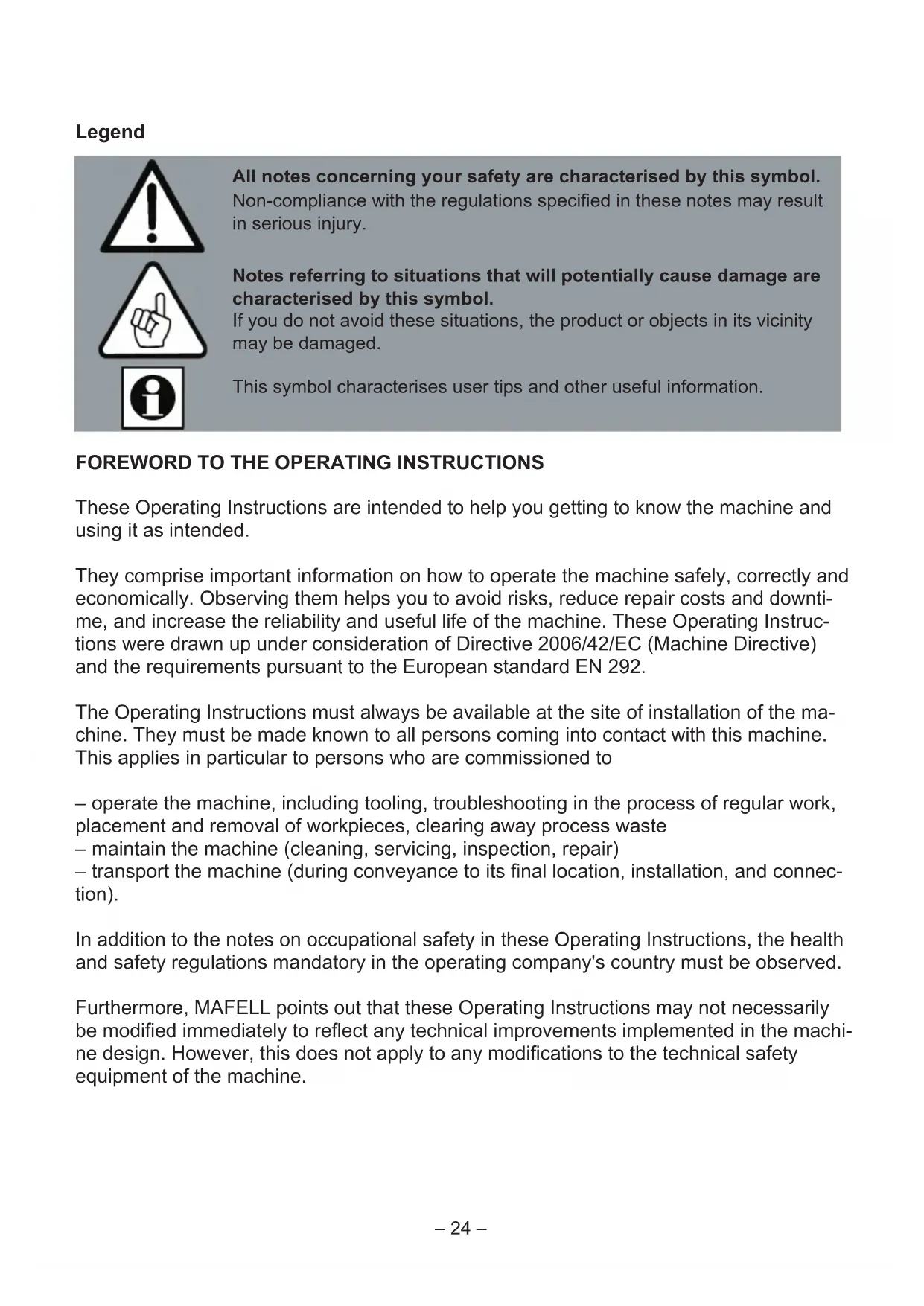
Legend

All notes concerning your safety are characterised by this symbol. Non-compliance with the regulations specified in these notes may result in serious injury.

Notes referring to situations that will potentially cause damage are characterised by this symbol. If you do not avoid these situations, the product or objects in its vicinity may be damaged.

This symbol characterises user tips and other useful information.
FOREWORD TO THE OPERATING INSTRUCTIONS
These Operating Instructions are intended to help you getting to know the machine and using it as intended.
They comprise important information on how to operate the machine safely, correctly and economically. Observing them helps you to avoid risks, reduce repair costs and downtime, and increase the reliability and useful life of the machine. These Operating Instructions were drawn up under consideration of Directive 2006/42/EC (Machine Directive) and the requirements pursuant to the European standard EN 292.
The Operating Instructions must always be available at the site of installation of the machine. They must be made known to all persons coming into contact with this machine. This applies in particular to persons who are commissioned to
- operate the machine, including tooling, troubleshooting in the process of regular work, placement and removal of workpieces, clearing away process waste
- maintain the machine (cleaning, servicing, inspection, repair)
- transport the machine (during conveyance to its final location, installation, and connection).
In addition to the notes on occupational safety in these Operating Instructions, the health and safety regulations mandatory in the operating company's country must be observed.
Furthermore, MAFELL points out that these Operating Instructions may not necessarily be modified immediately to reflect any technical improvements implemented in the machine design. However, this does not apply to any modifications to the technical safety equipment of the machine.
1 Information on the product
on the machine with art. no. 991201
1.1 Information on the manufacturer
MAFELL AG
1.2 Machine identification
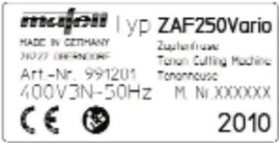
All data required for identification of the tenon cutting machine are located on the type label at the machine base.

CE sign for documentation of the conformance with the basic safety and health requirements according to Annex I of the Machine Directive.

Read the Operating Instructions carefully to reduce the risk of injury.
1.3 Technical data
Maximum timber dimension (width x height) for
-
tenon cutting at right angle 500 × 250 mm (19 11/16 x 9 27/32 in.)
-
tenon cutting with maximum inclination of 60° 220 × 250 mm (8 21/32 x 9 27/32 in.)
-
flattening at right angle and maximum tilt angle of 45° 340 × 250 mm (13 25/64 x 9 27/32 in.)
Maximum tendon length 110 mm (4 3/8 in.)
Maximum flattening in one process step 110mm (4 3/8 in.)
Maximum flattening depth 80mm (3 1/8 in.)
3-phase alternating current motor 400V ,50Hz
- rated input power (regular load) 6000 W
- rated output power (regular load) 4500 W
- rated current (regular load) 10.4 A
Tool (cutter head with cutter ring)
- cutter head diameter 100mm (3 15/16 in.)
- cutter ring diameter 165 mm (6 1/2 in.)
- cutter ring width 40 mm (1 9/16 in.)
- cutter head width (cutting width) 110mm (4 5/16 in.)
- tool holding fixture diameter 30mm (1 3/16 in.)
- rated idling speed 6670 rpm
speed at regular load 6260 rpm - cutting rate at regular load speed 32.8m / s (108 ft/s)
- feed rate 0.9-2.2 m/min. (2.9 - 7.2 ft/min)
- feed force approx. 800 N
- cutting length 320mm (12 5/8 in.)
- tilt range of tool assembly 0 - 60°
Machine dimensions and weight
width x length x height 1400 x 1400 x 1450 mm (55 x 55 x 57 3/32 in.)
- working height 780 mm (30 45/64 in.)
- dimensions of infeed table (W x L x H) 350 x 3000 x 900 mm
(1 3 3 / 4 × 1 1 8 7 / 6 4 × 3 5 1 / 2 in .)
weight without infeed table
weight of infeed table
-diameter of extraction connection pipe
3 8 0 kg (8 3 6 lbs) 8 3 kg (1 8 2. 6 lbs) 2 × 1 0 0 mm (3 1 5 / 1 6 in .)
1.4 Scope of delivery
Tenon cutting machine ZAF 250 Vario complete with:
-3 m (9.9 ft) infeed table
device for transport by fork-lift truck
- special milling tool
- operating tool
push-type grease gun
- Operating Instructions
1.4.1 Special accessories
- extraction kit
Order no. 202 320
1.5 Noise emission data
The average noise values over the total machining cycle are as follows:
| Tenon cutting | Flattening | |
| Noise level | 108 dB (A) | 108 dB (A) |
| workplace-related emission | 93 dB (A) | 94 dB (A) |
An additional K = 4 dB must be allowed on the above emission values for measuring inaccuracy.
The sound power level is measured pursuant to EN ISO 3746 with the following deviations:
- the correction factor for the background noise is max. 4 dB,
- at each measuring point, the balance between the noise level of the background noise and the machine noise level is greater than 6 dB.
the distance between the surface area of the machine and the measuring area is 1m - there are 9 measuring points,
- the measuring duration is equivalent to one machining cycle.
The sound power level of the workplace-related emission value is measured pursuant to EN ISO 11202 with the following deviations:
- the correction factor for the background at the measuring area as well as at the workplace is max. 4 dB.
- the balance between the noise level of the background noise and the noise level at the workplace is greater than 6 dB.
- the correction factor at the workplace is calculated pursuant to Annex 2 of EN ISO 11204.
Measurement on the basis of the following operating conditions:
Tenon cutting:
Cutting of a straight tenon with a thickness of 40mm (1 9/16 in.) and a length of 40mm (1 9/16 in.) at a 180 × 160mm (7 x 6 1/4 in.) workpiece of fir wood with the serial tool and the specified speed of 6260rpm (load speed).
Flattening:
Flattening at a 180 × 160 mm ( 7 × 6 1/4 in. ) fir wood workpiece at half the workpiece height (i.e. 80 mm ) to a depth of 70 mm ( 2 3/4 in ) with the serial tool (with cutter ring removed) and the specified speed of 6260 rpm (load speed).
The specified values are emission levels and not necessarily levels for safe operation. Irrespective of the existence of a correlation between the emission and the immission levels, these values cannot be used as a reliable decision basis regarding the need for additional precautions. The factors affecting the immission level at a workplace at a given time comprise the duration of the exposure, the properties of the premises, other noise sources etc., such as for instance the number of machines and other adjacent processing operations. Furthermore, the permissible immission level may differ from country to country. Nevertheless, this data gives the machine operator valuable information for a better estimation of the risks and dangers of the tenon cutting machine.
1.6 Machine description
The tenon cutting machine ZAF 250 makes it possible to manufacture straight and angled (max. 60° ) tenons fast, accurately, efficiently, and with exact tolerances, complete with an all-round chamfer and automatic face-grinding for angled tenons. The tooling change for the manufacture of flattenings is fast and simple. For all kinds of machining operations and for straight as well as for angled tenons, the workpiece always remains in the same position and does not require labour- and time-consuming moving. This is made possible by the integrated tilt position of the entire machining unit.
The 3m (9.9 ft) long infeed table safely supports the workpiece to be machined and can accommodate workpieces of up to 500× 250mm (19 11/16 x 9 27/32 in.) for straight tenons, and up to 220× 250mm (8 21/32 x 9 27/32 in.) for maximum tilt angle. The integrated double stop plate and the accurate scale allow for exact length measurement even in case of machining at both ends of the workpiece.
The combination cutting tool developed specifically for ZAF can be set easily and quickly to different tenon length and, after removal of the cutter ring, switched to flattening operation. It is equipped with replaceable hard metal reversible knives that can be reversed three times. Thus, a long operating life of the tool is guaranteed before the reversible knives need to be replaced.
The machine has easily accessible setting elements. Together with the clearly readable scales and the easily visible line laser, these elements allow for accurate setting of the desired geometry of tenon or flattening.
All electrical switches for controlling the machine are arranged at the clearly structured operating panel located directly at the workplace. Use the operating mode selection switch to preselect the operating mo
des Curtain closed, Setting, Manual milling, Tenon, and Flattening. In the operating mode Tenon and Flattening, all functions will run automatically after the start command has been given:
Closing the protection curtain, starting the drive motor for the cutting tool, tracing the tenon contour with face grinding, setting and chamfering, returning the tool to home position, switching off the drive motor, and opening the protection curtain.
The ZAF 250 Vario allows reduction of the feed to 50% .
At this setting, the powerful drive unit reliably meets the high requirements of the chip removal processes commonly applicable in a carpentry.
The chips resulting from machining are either ejected downwards through adjustable shutters, or - in case of stationary operation in a joining shop - may alternatively be disposed of into the extraction system via the standard hose connectors.
1.7 Safety devices
Already during the development of this new machine, optimum working conditions were one of our key concerns, from a number of mechanical and electrical safety features up to the consideration of ergonomic principles and measures to reduce the emission of noise and dust.
The machine is equipped with all protective devices required during its intended use to protect the operator and others from those risks that could not be eliminated by the machine design. This protective equipment comprises in particular:
1. Milling tool:
Designed pursuant to EN 847-1, with chip
thickness restriction, suitable for mechanical feed. Locking feature to prevent loosening during startup and shutdown by positive connection of the tool with the rear abutment flange by means of 2 driving pins.
- Protection against touching the tool: Housing fully closed with the exception of the opening for feeding the workpiece. The door in the housing providing access to the setting elements for adjusting the tenon thickness is guarded by means of a safety limit switch that is connected to the drive motor for the milling tool and the feed drive. When the door is opened, both drives are switched off, and the automatic brake shuts the tool down in approx. 3 seconds. The safety circuit of the control is designed to meet performance level PL=c pursuant to EN ISO 13849 (PL).
- Safety feature of the opening for workpiece feed-in:
The feed-in opening is adjusted to the dimensions of the respective workpiece by an automatically closing protection curtain pursuant to EN 1870-13.
- Clamping the workpiece:
The workpiece positioned in the machine is protected against accidental shifting by a manual clamping device.
- Protection against tool damage:
When the machine is set to cut angled tenons, a collision with the workpiece is prevented by automatic correction of the start position via retraction of the tool.
- Setup mode:
Setup mode, selected by means of the operating mode selection switch, is only available when the milling tool is in standstill. Then, the setting of milling unit can be changed in every direction by means of the inching control key.
- Chip disposal:
The chips are guided through the integrated chip deflection channel either to 2 ejection chutes or 2 hose connectors.
- Noise reduction:
The noise is reduced thanks to the almost circular shape of the milling tool and the closed housing. The duration of the emission is limited by automatic shutdown of the tool at the end of the machining cycle.
- Electrical safety:
The electrical equipment of the machine in in accordance with the European standard EN 60204-1. It is immune to interference by electromagnetic fields. There is no emittance of electromagnetic interference pulses.
1.8 Intended use
The MAFELL tenon cutting machine ZAF 250 is exclusively intended for cutting straight and angled tenons and to machine flattenings in solid timber with a maximum cross-section of 500 × 250 mm (19 11/16 x 9 27/16 in.) for straight tenons or 220 × 250 mm (8 21/32 x 9 27/32 in.) for tenons with a tilt angle of 60° . To this end, only the assembled milling tool comprised in the delivery with the dimensions 100 mm x 110 mm (3 15/16 x 4 5/16 in.) or 165 mm x 40 mm (6 1/2 x 1 9/16 in.) may be used.
The operator station of the machine is in front of the control panel that holds the switches for all machine functions.
Any use beyond the above is not considered intended use. The manufacturer waives any and all liability for resulting damage of any kind; the risk is exclusively borne by the user.
Likewise, the machine is not suitable for outdoor operation in rainy weather, or in hazardous areas.
To meet the requirements for 'intended use', the operating company must further
more observe the conditions for operation, maintenance and repair as specified by MAFELL, and the safety information in the Operating Instructions.
The tenon cutting machine ZAF 250 must only be used, tooled and maintained by individuals who are familiar with the machine and have been informed of its hazards. All repairs must be done by MAFELL representatives or MAFELL service agencies.
The applicable accident prevention regulations and other generally acknowledged stipulations in respect of safety technology and occupational health must be observed.
The manufacturer waives all liability for damage resulting from unauthorized modifications to the machine.
1.9 Residual risks
Also when the machine is used as intended and all applicable safety regulations are observed, there may occur residual risks that are attributable to the design of the machine for its intended purpose, for example:
- Touching the tool blades during tool change.
- Rupture of the tool and parts thrown from the machine.
- Sudden violent shifting of the tool when it is not clamped fast.
- Touching of live parts when the control cabinet is open and the main switch is not switched off, or the connecting cable not unplugged.
- Adverse effect on hearing in case of prolonged working without ear protection.
Emission of hazardous wood dusts in case of prolonged operation in closed rooms without sufficient ventilation.
1.9.1 Information in respect of the laser

Do not look directly into the laser beam!
- The laser is switched on and off with the main switch that is located on the side of the control cabinet.
- The laser opening is located in the top of the protective cover, to the left of the safety curtain. The laser radiates obliquely downwards (cut edge of the milling tool) onto the workpiece.
- Do not attach any additional optical instruments in front of the laser.
- Do not repair defects on the laser yourself.
- The built-in laser corresponds to class 2M and is thus safe for the human eye in case of brief exposure by eye lid closing reflex (looking into the beam for up to 0.25s)
1.10 Safety information

If used improperly, woodworking machines may be dangerous. For this reason, always observe the safety information in this section, the accident prevention regulations of your Employer's Liability Insurance Association, and the safety regulations applicable in your country!
General:
- Before starting to work, always check the safety devices for correct functions. Do not modify the machine in any way that might impair its safety.
- Children and teenagers are not allowed to operate this machine, with the exceptions of underage apprentices for training purposes under supervision of an expert.
- When working outdoors, only use rubber-insulated extension cables (for example
H07 RN-F) with a cross-section of no less than 5 × 2.5 mm2 . Take care not to pull the cable over sharp edges.
- Take the environmental influences into consideration. Do not expose the machine to rain. Avoid operating it in a moist or wet environment and close to combustible liquids or gases.
- When operating the machine out of doors, we recommend that you use a residual-current circuit breaker.
- Switch the main switch off before changing the milling tool and before troubleshooting.
- Only use the milling tools comprised in the delivery. Be sure never to use a blunt tool.
- When the machine is shut down for a longer period of time, secure the switched-off main switch against accidental activation by locking it with a padlock.
Information on the use of personal safety equipment
- Always wear closely fitting work clothes and remove rings, bracelets and wrist-watches before starting to work.
- Always wear suitable gloves when operating the tenon cutting machine and changing tools.
- To protect your eyes from injury, wear eye protection (goggles) or face protection when operating the machine.
- The noise level at the ear is greater than 85 dB (A). For this reason, wear ear protection when operating the machine.
Information on operation
- Always lead the electrical connecting cable away from the machine and lay it in such a way that there is no tripping hazard at the operator station.
-
Make sure that the operator station is freely accessible, sufficiently lighted, and slip-proof.
-
Ensure that there are no other individuals in the working space, in particular no children.
- Protect the workpiece from slipping or dropping by clamping it fast by means of the screw clamp provided for this purpose.
- Only switch the machine on if there is a workpiece in machining position.
- Check the workpiece for foreign particles. Do not cut into metal parts, for example nails, as this might damage the sensitive hard metal knives.
- Do not machine any workpieces that are too small or too big for the performance range of the machine.
- On no account change the angle position of the milling unit during an ongoing milling operation.
Information on maintenance and repair
- Before doing any maintenance or repair, always unplug the connecting cable from the socket at the machine, or switch off the main switch and protect it from accidental activation, for example by securing it with a padlock.
- Only use original MAFELL spares and accessories. The manufacturer does not accept any warranty claim and liability beyond the above.
- Regular checks of the machine, in particular of the guides of the milling unit and the smooth running of the protection curtain, are of major importance.
- Careful maintenance of the milling tool is significant as well. Keep it sharp and clean to allow for safe operation and good results. Observe the maintenance instructions and the notes for tool change.
2 Startup
2.1 Delivery and transport

The machine must not be lifted or transported with a crane or other hoisting gear, but only with a fork-lift truck.
Always use a fork-lift truck for unloading the machine and conveying it to its final installation location. Make sure that you always lift the machine from the operator side (the side with the control panel). It is imperative that both forks reach under the transport device bolted to the frame and marked in blue (no. 1 - Fig. 1).
When moving the machine, lift it just a few centimetres.
Check the machine for any transport damage immediately after unloading. Damaged packaging material may be an indication of improper transport. It is imperative that the forwarder confirm any transport damage in the bill of lading; otherwise, the forwarder's insurance will not cover the damage.
If the machine is not set up immediately after receipt, it must be stored in a dry place at temperatures between +5° and +40°C . For prolonged storage, it is advisable to check the rust-proofing of the uncoated parts occasionally and replace the coating if necessary.
2.2 Installation

When operated out of doors, the machine must be protected from the rain. It must not be operated in an hazardous environment.
Choose the place of installation of the machine in such a way that there is sufficient free space around it, considering the space taken up by the tenon cutting machine and the size of the workpieces to be machined. The footprint of the machine is shown in Fig. 3.
The machine does not need to be fastened. It must be placed on a floor capable of bearing its weight. By means of the adjustment screws at the machine base, horizontally align the tenon cutting machine with a spirit level placed on the workpiece support.
Then, screw down the 2 feet at the workpiece support table. Attach this table with the two provided hexagonal screws SW 13 to the machine, arranging it so that both support surfaces are aligned in height with each other, and the two vertical feed edges fall in line.
Caution: After installing the machine, it is imperative that you loosen the two 1 - Abb. screws (no. 2 - Fig. 1) to remove the transport device (no. 2 - Abb. 1). Otherwise, the milling unit will collide with this part in the course of its stroke!
2.3 Electrical connection

All work to the electrical system must only be done by a qualified electrician.
The machine is delivered fully wired and operative. The wiring diagrams are to the be found in the control cabinet.
It is connected to the electrical power supply via the 16A-CEE socket at the right of the control cabinet. As a minimum requirement, the supply line must comply with H07 RN-F and have a cross-section of 5 × 2.5 mm2 .
When connecting the machine, make sure that the operating voltage is 400V and the frequency between 50 and 60Hz . The actual voltage may be somewhat above or below the above operating voltage as long as a tolerance range of ± 10% is not exceeded. Slow 16-A fuses must be provided as operative backup fuses by the customer.
Furthermore, observe the correct sense of rotation of the milling tool. To check it, look through the workpiece feed-in opening: the tool must rotate anti-clockwise. If it does not, disconnect the connecting cable and change 2 phases in the socket (for example L1 and L2).
2.4 Dust extractor connection
The tenon cutting machine is intended for operation without dust extraction as well as for connection to an in-plant dust extractor system. To this end, it has 2 connection nozzles of 100mm (3 15/16 in.) diameter each (no. 3 - Fig. 2).
In case of operation in closed rooms, the machine must be connected to a dust extractor system that allows for air speeds of no less than 20m / s (65.6 ft/s) at both connection nozzles. The resulting vacuum amounts to 258 Pa. Flame retardant, flexible extraction hoses must be used whose cross-section up to the point of junction must be at least equal to that of the connection nozzles. After the junction, the cross-section of the hose must be at least 140 mm (5 1/2 in.).
For outdoor operation or working briefly in closed rooms, the machine can be retrofitted so that the chips fall beneath it. To this end, the screws provided on both sides (no. 5 - Fig. 4) are loosened, and the shutters (no. 4 - Fig. 4) are opened. Retighten the screws afterwards.

Never reach into the running machine via the open shutters, for example to removed a buildup of chips. Danger of touching the running milling tool!
3 Operation
3.1 Initial startup

Before initial startup of the tenon cutting machine, it is imperative that you observe the following notes:
- These Operating Instructions must be made known to all individuals commissioned to operate the machine. In particular, their attention must be drawn to the section "Safety information".
- You must check that all protection devices have been installed and are operative.
- When operated in closed rooms, the machine must be connected to an in-plant dust extractor system, and the air speeds at the connection nozzles must be at least 20m / s (65.6 ft/s). The resulting vacuum amounts to 258 Pa. Furthermore, ensure that the dust extractor system is automatically activated when the machine is switched on.
- The air speed must be checked on initial commissioning and after significant modifications.
- The suction devices must be checked prior to initial commissioning, daily for obvious defects and monthly for their effectiveness.
- Ensure that the individual reversible knifes of the milling tool are tightened correctly, and that the tool is fastened safely on the drive shaft. (See the section "Tool change" for the tightening torques.)
- With the machine idling, check the milling tool for correct sense of rotation (see section "Electrical connection").
3.2 Switchgear
All setting elements of the electrical switchgear of the machine are provided in the control cabinet at the operator station (see Fig. 5). The individual switches shown in Fig. 5 have the following functions:
6: Main switch: Disconnects the entire electrical equipment from the mains. In position 0, it can be secured with a padlock. It has 2 switch positions:
0: off (machine disconnected from the mains).
1: on (machine is live and operative).
7: Operating mode selector switch: Is used to preselect an operating mode. The individual switch positions have the following significance:
0: Close curtain: The protection curtain closes.
1: Setup mode: To check the preset paths, the individual feed movements of the milling unit can be tested by means of the 4 pushbuttons (10). The movement continues as long as you keep the respective pushbutton pressed. It is not possible to switch on the drive of the milling tool. The protection curtain remains open.
2: Manual milling: Press the Start key and keep it pressed to close the protection curtain and start up the mil- ing motor.
Press the 4 pushbuttons to execute the individual feed movements of the milling unit. The unit only moves as long as you keep the respective pushbutton and the Start key pressed. When you release the Start key, the milling motor switches off immediately, the feed movement is aborted, and the protection curtain opens automatically.
3: Preselection for tenon cutting: All 4 feed movements are activated.
4: Preselection for flattening: Only the horizontal feed is activated.
8: Start pushbutton for enabling the milling process: Depending on the selected operating mode (tenon or flattening), the process runs automatically. The milling tool drive is switched off after it has returned to home position. When the positions "0" or "1" are selected at the operating mode selection switch, this start pushbutton is not active.
9: EMERGENCY STOP pushbutton: Aborts the milling process in case of danger, and aborts all movements.
10: Pushbutton for moving the milling unit in setup mode and during manual milling: Press the respective pushbutton for each of the 4 feed movements X+ , X- , Z+ , Z+ . The selected movement only continues as long as you keep the pushbutton pressed.
11: Stop button for interrupting the milling operation
3.3 Switching on and off
To switch the machine on, first set the main switch to position "1" and the operating mode selection switch to the desired operating mode. Then, initiate the entire milling process by pressing the Start pushbutton. After completion of the process, the milling unit returns to home position where it is switched off automatically. The automatic brake reduces the slowing time to approx. 3 seconds. After that, the protection curtain opens. That is to say that the machine switches off automatically.
Use the EMERGENCY STOP pushbutton only for fast shutdown in an emergency.
3.4 Cutting straight tenons
Before machining, roughly cut off the workpiece.
When cutting straight tenons, make sure that the pointer (no. 13 - Fig. 9) points to the value "0" at the indicator scale (no. 14) at the segment for tilting. If this is not the case, loosen the handle lever (no. 15). Now, you can tilt the entire milling unit with the housing to point to this value. After tilting, re-tighten the handle lever.
Never tilt the milling unit with the protection curtain closed!
To set the tenon dimensions and for subsequent machining, proceed as follows:
- Set the operating mode selection switch (no. 7 - Fig. 5) to position "1" and fold open the lid of the machine housing.
- Check or set tenon length "t" (see Fig. 6) at the milling tool (see section 4.1, Tool change).
- Press the pushbuttons "Z-" and "X-" (no. 10 - Fig. 5) to move the milling unit to home position.
- Set the tenon thickness "Z2" (see Fig. 6) by shifting the clamping ring (no. 19 - Fig. 11). To do so, first loosen the clamping lever (no. 43 - Fig. 11). The pointer must point to the value for the desired tenon thickness on the scale (no. 20). Then, re-tighten the clamping lever (43).
- By pressing the pushbutton "Z+", move the milling unit up until the spiral dowel sleeve (no. 16 - Fig. 10) no longer bears down on it. Then, loosen the clamping lever (no. 15) and shift the adjustment disk (no. 17) until the desired flattening dimension "Z1" (Fig. 6) is indicated on the scale (no. 18) between the lower edge of the tenon and the lower edge of the workpiece. Then, re-tighten the clamping lever (no. 15).
- To ensure that the tenon starts at the edge of the workpiece, check that the value "0" is indicated at the edge of the housing on the scale (no. 12 - Fig. 8). If this is not the case, adjust the value accordingly with the hand wheel (no. 11).
- By turning the hand wheel (no. 21 - Fig. 12), adjust the horizontal path of the milling unit in such a way that the position indicator shows at least the width of the workpiece. We recommend to add a safety margin of some mm to this value.
- Press the pushbutton "Z-" to return the milling unit to the lower end position.
Then, set the operating mode selection switch (no.7- Fig. 5) to position "3" and close the lid of the machine housing.
- For one-sided tenons, loosen the handle lever (no. 27 - Fig. 15) to set the double stop plate in such a way that the pointer (no. 28) points to the finished timber length without tenon length "t" (see Fig. 6) on the scale (no. 29). Re-tighten the handle lever. Lay the workpiece against the contact edge of the workpiece support and insert it into the slide-in opening. Fold down the front stop shutter (no. 30 - Fig. 15) and push the workpiece against it.
Then, fix the workpiece with the screw clamp (no. 26 - Fig. 14). Press the Start pushbutton (no. 8 - Fig. 5). The protection curtain closes. The milling head automatically follows the preset tenon contour. Simultaneously, the tenon is chamfered.
After completion of the cycle, the mil-ling motor returns to home position and is switched off. The protection curtain opens automatically.
- For double-sided tenons, set the workpiece length as described above in section 9. Additionally, set the knurling screw (raw timber stop) in the rear shutter to the tenon length pursuant to the scale at the double stop. Lock it with the clamping screw (no. 32). Lay the workpiece against the contact edge of the workpiece support and insert it into the slide-in opening until it hits the raw timber stop. Clamp down the workpiece and cut the first tenon. After the milling tool has come to a standstill, loosen the clamp, reverse the workpiece until it touches the front stop with the base surface (not the tenon), and clamp it down. Then, cut the second tenon.
3.5 Cutting straight shouldered tenons
Also with this type of tenon, it is important to check that the pointer (no. 13 - Fig. 9) points to the value "0" at the indicator scale (no. 14) at the segment for tilting.
Never tilt the milling unit with the protection curtain closed!
To set the tenon dimensions and for subsequent machining, proceed as follows:
- Perform the steps 1 to 5 described in section 3.4.
- By turning the hand wheel (no. 11 - Fig. 8) at the edge of dimension "X1" (see Fig. 6) pursuant to the scale (no. 12) at the 6).
- By turning the hand wheel (no. 21 - Fig. 12), set the horizontal path of the milling unit in such a way that the position indicator shows the width of the tenon + the shoulder dimension "X1".
Example: For a desired tenon width of 10 cm and a shoulder dimension of 3 cm, set the pointer to a dimension of 13 cm.
- Perform the steps 8 to 10 described in section 3.4.
3.6 Cutting angled tenons
Important: Before machining, the workpiece must be cut diagonally in accordance with the desired angle!
To set the tenon dimensions and for subsequent machining, proceed as follows:
- Loosen the handle lever (no. 15 - Fig. 9) and tilt the milling unit until the pointer (no. 13) points to the finished angle on the scale (no. 14). Then, re-tighten the handle lever.

Never tilt the milling unit with the protection curtain closed!
- Set the operating mode selection switch (no. 7 - Fig. 5) to position "1" and fold open the lid of the machine housing.
- To set the tenon dimensions "t" and "Z2" and the distance "Z1" (see Fig. 6) between lower edge of tenon and lower edge of workpiece, follow the steps described in paragraph 2 to 6 of section 3.4.
- Set the horizontal travel path of the milling unit by means of the hand wheels (no. 11 - Fig. 8) and (no. milling unit 12). First, use the hand wheel (no. 11 - Fig. 8) to set the face-grinding dimension "0" or the shoulder dimension "X1" as described under 3.5.2. Now, using the handwheel (no. 21 - Fig. 12) set the horizontal path as described in 3.5.3
- Press the pushbutton "Z-" to return the milling unit to the lower end position. Then, set the operating mode selection switch (no. 7 - Fig. 5) to position "3" and close the lid of the machine housing.
- Lay the marked workpiece against the contact edge of the workpiece support und insert it into the slide-in opening until the mark is aligned with the 0 position (Fig. 14), which correspond to the line projection of the laser. Then, fix the workpiece with the screw clamp (no. 26 - Fig. 14).
- Press the Start pushbutton (no. 8 - Fig. 5). The protection curtain closes. The milling head automatically follows the preset tenon contour, including face-grinding and producing a shoulder. Simultaneously, the tenon is chamfered. After completion of the cycle, the milling motor returns to home position and is switched off. The protection curtain opens automatically.
3.7 Cutting vertical tenons
The machine design also allows for cutting vertical tenons (see Fig. 17). Note that this type of machining is only suitable for maxi
mum workpiece heights of 160 mm (6 1/4 in.). Also with this type of tenon, it is important to check that the pointer (no. 13 - Fig. 9) points to the value "0" at the indicator scale (no. 14) at the segment for tilting.
Never tilt the milling unit with the protection curtain closed!
To set the tenon dimensions and for subsequent machining, proceed as follows:
- Set the operating mode selection switch (no. 7 - Fig. 5) to position "1" and fold open the lid of the machine housing.
- Check or set tenon length "t" (see Fig. 17) at the milling tool (see section 4.1, Tool change).
- Press the pushbuttons "Z-" and "X-" (no. 10 - Fig. 5) to move the milling unit to home position.
- To ensure that the tenon extends over the whole height of the workpiece, adjust the clamping ring (no. 19 - Fig. 11) so that the pointer attached to the clamping ring points to the workpiece height on the scale (no. 20).
- Press the pushbutton "Z+" to move the milling unit up until the spiral dowel sleeve (no. 16 - Fig. 10) no longer bears down on it. To have the tenon start at the bottom workpiece surface, loosen the clamping lever (no. 15) and shift the adjustment disk (no. 17) until the value "0" is indicated on the scale (no. 18). Then, re-tighten the clamping lever (no. 15).
- By turning the hand wheel (no. 11 - Fig. 8, set the dimension "X1" (see Fig. 17) at the edge of the housing pursuant to the scale (no. 12).
- By turning the hand wheel (no. 21 - Fig. 12), set the horizontal path of the milling unit in such a way that the position indicator shows the width of the tenon "d" + the dimension "X1" (see Fig. 17).
Example: For a desired tenon width of 4 cm and an edge distance of 8 cm, set the pointer to a dimension of 12 cm.
- Perform the steps 8 to 10 described in section 3.4.
3.8 Flattening
Cut the workpiece to the exact angle and length. During flattening (see Fig. 7), the path of the milling unit is limited to the horizontal movement required for this type of machining. This speeds up machining and saves time.
To set the flattening dimensions and for subsequent machining, proceed as follows:
- Check whether the indicator (no. 13 - Fig. 9) points to the value "0" at the indicator scale (no. 14) at the segment for tilting. If this is not the case, loosen the handle lever (no. 15) to correct the position of the segment for tilting accordingly.

Never tilt the milling unit with the protection curtain closed!
- Set the operating mode selection switch (no. 7 - Fig. 5) to position "1" and fold open the lid of the machine housing.
- Remove the cutting ring (no. 38 - Fig. 18 (see section 4.1).
- Press the pushbuttons "Z-" and "X-" (no. 10 - Fig. 5) to move the milling unit to home position.
- Press the pushbutton "Z+" to move the milling unit up until the spiral dowel sleeve (no. 16 - Fig. 10) no longer bears down on it. Then, loosen the clamping lever (no. 15) and shift the adjustment disk (no. 17) until the desired flattening dimension "Z1" is indicated on the scale (no. 18) (see Fig. 7). Then, retighten the clamping lever (no. 15).
- To ensure that the flattening starts at the edge of the workpiece, check that the value "0" is indicated at the edge of
the housing on the scale (no. 12 - Fig. 8). If this is not the case, adjust the value accordingly with the hand wheel (no. 11).
- By turning the hand wheel (no. 21 - Fig. 12), set the horizontal path of the milling unit in such a way that the position indicator shows at least the width of the workpiece. We recommend to add a safety margin of some mm to this value.
- Press the pushbutton "Z-" to return the milling unit to the lower end position. Then, set the operating mode selection switch (no. 7 - Fig. 5) to position "4" and close the lid of the machine housing.
- For flattenings, loosen the handle lever (no.27 - Fig. 15) and set the double stop plate in such a way that the pointer (no. 28) points to the finished timber length without flattening length "t" on the scale (no. 29) (see Fig. 7). Re-tighten the handle lever. Lay the workpiece against the contact edge of the workpiece support and insert it into the slide-in opening until it hits the front shutter of the double stop plate. Then, fix the workpiece with the screw clamp (no. 26 - Fig. 14).

Per work step, the blade length "t" can be max. 110mm (4 3/8 in.).
For longer blades, machining must be divided into several steps. (The rear shutter of the double stop plate may possibly be used).
- Press the Start pushbutton (no. 8 - Fig. 5). The protection curtain handles. The milling head automatically follows the preset flattening contour. After completion of the cycle, the milling motor returns to home position and is switched off. The protection curtain opens automatically.
- Lay the marked workpiece against the contact edge of the workpiece support and insert it into the slide-in opening
until the mark "t" is aligned with the 0 position (corresponds to the line projection of the laser). Observe the maximum machining length of 110mm (4 3/8 in.) per work step. Now, fix the workpiece with the screw clamp (no. 26 - Fig. 14).
3.9 Feed control
The ZAF 250 Vario has the option to reduce the feed rate of the feed motors to 50% of the regular rate.
To select this setting, turn the potentiometer on the top left of the control panel.
4 Tooling and maintenance

Before starting to do any maintenance work, either switch off the main switch and protect it against accidental re-activation, or disconnect the power plug!
4.1 Tool change
The milling tool delivered with the tenon cutting machine has been developed specifically for this machine. It consists of the cutter head (no. 37 - Fig. 18) and the cutter ring (no. 38) fitted with replaceable hard metal reversible knives. This eliminates the need for labour- and time-intensive sharpening of the tool: When the hard metal reversible knives are dull, they only require reversing or replacing. Proceed as follows:
- Check whether the indicator (no. 13 - Fig. 9) points to the value "0" at the indicator scale (no. 14) at the segment for tilting. If this is not the case, loosen the handle lever (no. 15) to correct the position of the segment for tilting accordingly.
Never tilt the milling unit with the protection curtain closed!
-
Set the operating mode selection switch (no. 7 - Fig. 5) to position "1".
-
By pressing the pushbuttons (no. 10 - Fig. 5), to move the milling unit so that it is positioned in the centre of the slide-in opening.
- To hold up, insert the pin (no. 39 - Fig. 18) into the provided bore of the cutter head. With the Allen key SW 10 (no. 40), unscrew the clamping screw (no. 41) and remove the clamping disk (no. 42).
- Loosen the bolted hard metal reversible knives with the provided Allen key, turn them by 90° , and re-tighten them to 4 Nm. After three reversals, replace them by new reversible knives.
- For tenon cutting, loosen the cutter ring (no. 38) and shift it on the cutter head (no. 37) until the front edge of the cutter ring points to the desired tenon length "t" on the scale provided on the cutter head (see Fig. 6). Then, re-tighten the cutter ring to 15Nm . For flattening, remove the cutter ring completely. Thanks to the distortion lock between the two parts, it can only be removed in one direction.
- Remove any clinging chips and dust from the tool spindle and the clamping surfaces and position the tool. Ensure that the two driving pins at the spindle engage with the two bores of the tool. Screw in the clamping screw (no. 41) with the clamping disk (no. 42) and tighten it.
- Press the pushbuttons "Z-" and "X-" (no. 10 - Fig. 5) to move the milling unit to home position.
4.2 Machine servicing
Clean the machine regularly to extend its useful life, avoid unnecessary repairs, and meet the requirements for excelling cutting and milling quality. The MAFELL tenon cutting machine is designed to require little maintenance and care. Depending on the degree of soiling, it should be cleaned at
least once per week. This goes in particular for the guides of the milling unit and the spindles for the dimensions setting functions.
Remove any clinging chips and dust with a vacuum cleaner. To remove any residual resin, it is advisable to use a resin-solving detergent. It is imperative that you wipe all parts treated in this way with an oil-moistened rag to avoid the formation of rust.
To prevent excessive motor heating, regularly check that the ventilation slots are not clogged by dust. Always use a vacuum cleaner for dust removal; blowing off the dust would direct it into the interior of the motor.
Use a grease gun to grease the feed spindle nuts with acid-free grease at the two provided nipples when necessary.
The provided ball-bearings have a lifetime lubrication and normally do not require any maintenance.
For all grease point, only use our special grease, order no. 049040 (1 kg tin).
After a long period of operation, we recommend to have the machine checked by MAFELL service technicians.
4.3 Tool servicing
All resin should be regularly cleaned off the milling tool as clean tools help to improve the quality of the cuts. Do not use heavily alkaline agents. Only clean the tool with acid-free detergents. To remove the resin from the milling tool, deposit it for 24 hours in petroleum or another commercially available deresinification agent.
4.4 Motor brake
The drive motor for the milling tool is equipped with a mechanical spring-loaded brake that is enabled automatically when the machine is switched off. This reduces the slowing-down time of the knife shaft to approx. 3 seconds.
Excessively frequent switching on and off may result in overheating and damage of
the brake. For this reason, do not switch on and off the machine (and thus activate the brake) more often than approx. 40 times per hour.
The brake is designed to execute approx. 30,000 braking actions. With increasing wear of the brake disk, the slowing-down time will increase. When slowing down takes more than 4 seconds, the brake must be replaced.
5 Troubleshooting

Always proceed with special caution and circumspection when troubleshooting. As a first step, always switch off the main switch or pull the power plug.
Some of the most common faults and their causes are explained in the following. If your machine displays other faults, please contact your dealer or the company MAFELL directly.
| Fault Cause Remedy | ||
| The machine does not switch on. | Power line not plugged in. Plug | in the power line at the socket at the control cabinet. |
| Main switch is not switched on. | Switch on the main switch and start the machine. | |
| Failure of power supply on one or several phases. | Check the power supply in the building. | |
| EMERGENCY STOP push-button has been pressed. | Unlock the EMERGENCY STOP pushbutton by pulling it up. Switch the machine on. | |
| Operating mode selection switch is in switch position "0" or "1". | Set the operating mode selector switch to position "2", "3", or "4" depending on the desired machining type. | |
| Overload protection has triggered. | Remedy the cause of the overload. Wait for the machine to cool, and re-activate the motor protection switch in the control cabinet. | |
| Terminal with fuse has tripped | Check free movement of protective curtain. Clean if necessary. | |
| Milling motor does not start. Machine cover not closed. Close | cover | |
| Machine switches off during machining. | The overload protection triggers, for example because of failure of one or several mains phases. | Identify and remedy the cause of the overload. Before swit-ching the machine on, re-ac- tivate the motor protection switch. |
| The machining was not executed correctly. | Incorrect machine settings. Check the setting in accordan- ce with the selected machi- ning type (see sections 3.4 through 3.8). | |
| Uneven workpiece surface. Tool blades of the reversible knives are blunt. | Reverse or replace the reversible knives (see section 4.1). | |
| Chip ejection clogged. Timber is too moist, or machi- ne has been operated for too long without chip removal. | Remove the chips below the vertical chutes of the machine. | |
| Machine is set to operation with dust extractor system. | Open the shutters at the verti- cal chutes (see section 2.4). | |
| When operated with dust ex-tractor system: connection no- zzle clogged. | Insufficient extraction rate at the connection nozzles. | Increase the air speeds at the connection nozzles to at least 20 m/s (65.6 ft/s). |
| Slowing-down time of the mil- ling tool is longer than 4 se-conds. | Brake defective, or brake pads worn. | Have the MAFELL customer service replace the brake. |
| No or halting feed movement under load. | Safety clutch worn, or set to an excessively low value. | Tighten the safety clutch by one sprocket (see page 79 Fig. 19). |
6 Exploded drawing and spare parts list
The corresponding information in respect of spare parts can be found on our homepage: www.mafell.com
François
Sommaire Page
Electrical connection
For the electrical connection, a quality H07 RN-F cable with a cross-section of min. 5 x 2.5mm2 and a 16 ACEE socket must be used. A slow 16 A fuse must be connected in series for protection.
Raccordement electrique

- AVERTISSEMENT
- GB - EC DECLARATION OF CONFORMITY
- LEGEND
- FOREWORD TO THE OPERATING INSTRUCTIONS
- 1 INFORMATION ON THE PRODUCT
- 1.1 INFORMATION ON THE MANUFACTURER
- 1.2 MACHINE IDENTIFICATION
- 1.3 TECHNICAL DATA
- 1.4 SCOPE OF DELIVERY
- 1.4.1 SPECIAL ACCESSORIES
- 1.5 NOISE EMISSION DATA
- TENON CUTTING
- FLATTENING
- 1.6 MACHINE DESCRIPTION
- 1.7 SAFETY DEVICES
- MILLING TOOL
- 1.8 INTENDED USE
- 1.9 RESIDUAL RISKS
- 1.9.1 INFORMATION IN RESPECT OF THE LASER
- 1.10 SAFETY INFORMATION
- GENERAL
- INFORMATION ON THE USE OF PERSONAL SAFETY EQUIPMENT
- INFORMATION ON OPERATION
- INFORMATION ON MAINTENANCE AND REPAIR
- 2 STARTUP
- 2.1 DELIVERY AND TRANSPORT
- 2.2 INSTALLATION
- 2.3 ELECTRICAL CONNECTION
- 2.4 DUST EXTRACTOR CONNECTION
- 3 OPERATION
- 3.1 INITIAL STARTUP
- 3.2 SWITCHGEAR
- 3.3 SWITCHING ON AND OFF
- 3.4 CUTTING STRAIGHT TENONS
- 3.5 CUTTING STRAIGHT SHOULDERED TENONS
- 3.6 CUTTING ANGLED TENONS
- 3.7 CUTTING VERTICAL TENONS
- NEVER TILT THE MILLING UNIT WITH THE PROTECTION CURTAIN CLOSED
- 3.8 FLATTENING
- 3.9 FEED CONTROL
- 4 TOOLING AND MAINTENANCE
- 4.1 TOOL CHANGE
- 4.2 MACHINE SERVICING
- 4.3 TOOL SERVICING
- 4.4 MOTOR BRAKE
- 5 TROUBLESHOOTING
- 6 EXPLODED DRAWING AND SPARE PARTS LIST
- FRANÇOIS
- SOMMAIRE PAGE
- ELECTRICAL CONNECTION
- RACCORDEMENT ELECTRIQUE
Brand : Mafell
Model : ZAF 250 Vario
Category : Milling machine