
Super Finish 23 CR - Paint gun WAGNER - Free user manual and instructions
Find the device manual for free Super Finish 23 CR WAGNER in PDF.
| Product Type | Electric Airless Paint Sprayer |
| Brand | WAGNER |
| Model | Super Finish 23 CR |
| Maximum working pressure | 25 MPa (250 bars) |
| Maximum flow rate | 2,6 L/min |
| Flow rate at 12 MPa (120 bars) with water | 2,38 L/min |
| Maximum product temperature | 43 °C |
| Maximum product viscosity | 20 000 mPas |
| Weight (empty) | 37 kg |
| Power consumption | 1,3 kW |
| Maximum current consumption | 7,0 A |
| Protection type | IP 54 |
| Power cord length | 6 m |
| Maximum sound pressure level | 75 dB(A) at 1 m |
| Maximum vibration at gun | < 2,5 m/s² |
| Hydraulic oil quantity (body) | 1,3 L |
| Gear grease quantity | 45 g |
| Power supply | Safety power outlet with earth, differential protection ≤ 30 mA |
| Application areas | Workshop and construction site, spraying of varnishes, dispersions, foams and injection resins |
| Usable coating products | Varnishes, water-based and solvent-based paints, 2K, dispersions, latex, foams and injection resins |
| Filtration | Suction strainer and filter cartridge in the gun |
| Safety | Gun lock, mandatory grounding, injection protection |
| Warranty | 36 months (extendable to 60 months under conditions), 12 months for intensive use |
Frequently Asked Questions - Super Finish 23 CR WAGNER
User questions about Super Finish 23 CR WAGNER
0 question about this device. Answer the ones you know or ask your own.
Ask a new question about this device
Download the instructions for your Paint gun in PDF format for free! Find your manual Super Finish 23 CR - WAGNER and take your electronic device back in hand. On this page are published all the documents necessary for the use of your device. Super Finish 23 CR by WAGNER.
USER MANUAL Super Finish 23 CR WAGNER

SUPER FINISH 23 CR
AIRLESS HIGH-PRESSURE SPRAYING UNIT ORIGINALBETRIEBSANLEITUNG

- D - Betriebsanleitung 2
- GB - Operating manual 28
- F - Mode d'emploi 53
- I - Istruzioni per l'uso 79
10 REPARATUREN AM GERÄT 15
1.2 EXPLOSIONSSCHUTZ

Gefahr
b) Vertikalbetrieb:

4.4 ANSAUGSYSTEM
10 REPARATUREN AM GERÄT
Gefahr
Gerät ausschalten.
10.2 EINLASSVENTIL
Montage
10.4 DRUCKREGELVENTIL
11.2 ERSATZTEILLISTE SUPER Finish 23 CR
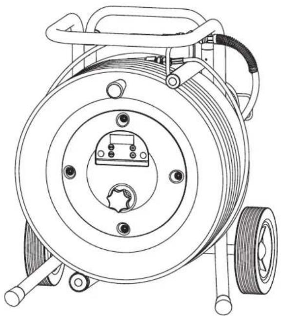
11.3 ERSATZTEILLISTE WAGEN
| POS. | BESTELL-NR BENENNUNG |
| 1 2415521 | Wagen kpl. (inkl. Pos 2-4) |
| 2 2402496 | Deichsel kpl. |
| 3 2402494 | Rad (1 Stk.) |
| 4 9994950 | Radkappe (1 Stk.) |

go.wagner-group.com/profi
PRÜFUNG DES GERÄTES
www.wagner-group.com/profi-guarantee.
Division Professional Finishing
Otto Lilienthal Strasse 18
88677 Markdorf
Translation of the original operating instructions
WARNING!
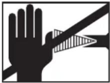
Attention, danger of injury by injection!
Airless units develop extremely high spray pressures.
  Danger Danger | |
| 1 | Never bring fingers, hands or other body parts into contact with the spray jet!Never point the spray gun at yourself, other persons or animals.Never use the spray gun without spray jet safety guard.Do not treat a spray injury as a harmless cut. In case of injury to the skin by coating material or solvents, consult a doctor for quick and correct treatment. Inform the doctor about the coating material or solvent used. |
| 2 | The following points are to be observed in accordance with the operating manual before every start-up:Faulty units may not be used.Secure a Wagner spray gun with the securing lever at the trigger guard.Ensure earthing.Check the permissible operating pressure of the high-pressure hose and spray gun.Check all the connecting parts for leaks. |
| 3 | Instructions for regular cleaning and maintenance of the unit are to be observed strictly.Observe the following rules before any work on the unit and at every working break:Relieve the pressure from the spray gun and high-pressure hose.Secure a Wagner spray gun with the securing lever at the trigger guardSwitch the unit off. |
Ensure safety!
Contents
1 SAFETY REGULATIONS FOR AIRLESS SPRAYING 30
1.1 Flash point ____
1.2 Explosion protection ____
1.3 Danger of explosion and fire from sources of ignition during spraying work ____ 30
1.4 Danger of injury from the spray jet ____ 30
1.5 Secure spray gun against unintended operation _ 30
1.6 Recoil of spray gun 30
1.7 Breathing equipment as protection against solvent vapors ____ 30
1.8 Prevention of occupational illnesses 30
1.9 Max. operating pressure 31
1.10 High-pressure hose
1.11 Electrostatic charging (formation of sparks or flames) ____ 31
1.12 Use of units on building sites and workshops ____ 31
1.13 Ventilation when spraying in rooms ____ 31
1.14 Suction installations
1.15 Earthing of the object 31
1.16 Cleaning the unit with solvents 31
1.17 Cleaning the unit 31
1.18 Work or repairs at the electrical equipment ____ 31
1.19 Work at electrical components 32
1.20 Setup on an uneven surface 32
2 GENERAL VIEW OF APPLICATION 32
2.1 Application 32
2.2 Coating material ____
2.2.1 Coating materials with sharp-edged additional materials ____ 32
2.2.2 Filtering (for spay work) 32
3. DESCRIPTION OF UNIT 33
3.1 Functioning of the unit 33
3.2 Two-position operation ____
3.3 Explanatory diagram
3.4 Technical data
4 STARTUP 35
4.1 Gun 35
4.2 High pressure hose and pressure gauge ____ 36
4.3 Hopper 36
4.4 Suction system 36
4.5 Connection to the mains network 37
4.6 Cleaning preserving agent when starting-up of operation initially ____ 37
4.6 Ventilate unit (hydraulic system) if the sound of 30 inlet valve is not audible ____ 36
4.7 30aking the unit into operation with coating material ____ 36
5 TRANSPORTATION 38
6 HANDLING THE HIGH-PRESSURE HOSE 38
7 INTERRUPTION OF WORK 38
8 CLEANING THE UNIT 39
8.1 Cleaning the unit from the outside ____ 39
8.2 Suction filter 39
8.3 Cleaning the Airless spray gun ____ 40
9 SERVICING 40
9.1 General servicing ____ 40
9.2 High-pressure hose ____
10 REPAIRS AT THE UNIT 41
310.1 Inlet valve Pusher 41
10.2 Inlet valve 41
10.3 Outlet valve 42
10.4 Pressure control valve 42
10.5 Typical wear parts 42
10.6 Remedy in case of faults 45
11 SPARE PARTS AND ACCESSORIES 44
11.1 Super Finish 23 CR accessories ____ 44
11.2 Spare parts list Super Finish 23 CR ____ 49
32 11.3 Spare parts List Trolley 50
11.4 Spare parts list hopper 5l ____ 50
Testing of the unit 51
Important information on product liability 51
Note on disposal 51
Guarantee declaration 51
CE - declaration 52
European service network 132
1 SAFETY REGULATIONS FOR AIRLESS SPRAYING
All local safety regulations in force must be observed.
The following sources are just a sample of those containing safety requirements for Airless spraying.
a) The European Standard „Spray equipment for coating materials – safety regulations „ (EN 1953).
The following safety regulations are to be observed in order to ensure safe handling of the Airless high-pressure spraying unit.
1.1 FLASH POINT

Only spray coating materials with a flash point of 21 °C or higher.
The flash point is the lowest temperature at which vapors develop from the coating material. These vapors are sufficient to form an inflammable mixture over the air above the coating material.
1.2 EXPLOSION PROTECTION

Do not use the unit in work places which are covered by the explosion protection regulations. The unit is not designed to be explosion protected. Do not operate the device in explosive areas (zone 0, 1 and 2). Explosive areas are, for example, places where paints are stored and locations in direct proximity to the object being sprayed. Keep the device at least 3 m from the object you are spraying.
1.3 DANGER OF EXPLOSION AND FIRE FROM SOURCES OF IGNITION DURING SPRAYING WORK

There must be no sources of ignition such as, for example, open fires, lit cigarettes, cigars or tobacco pipes, sparks, glowing wires, hot surfaces, etc. in the vicinity.
1.4 DANGER OF INJURY FROM THE SPRAY JET

Attention, danger of injury by injection! Never point the spray gun at yourself, other persons or animals.
Never use the spray gun without spray jet safety guard.

The spray jet must not come into contact with any part of the body.
In working with Airless spray guns, the high spray pressures arising can cause very dangerous injuries. If contact is made with the spray jet, coating material can be injected into the skin. Do not treat a spray injury as a harmless cut. In case of injury to the skin by coating material or solvents, consult a doctor for quick and correct treatment. Inform the doctor about the coating material or solvent used.
Always secure the spray gun when mounting or dismounting the tip and in case of interruption to work.
1.6 RECOIL OF SPRAY GUN

When using a high operating pressure, pulling the trigger guard can effect a recoil force up to 15 N.
If you are not prepared for this, your hand can be thrust backwards or your balance lost. This can lead to injury.
1.7 BREATHING EQUIPMENT AS PROTECTION AGAINST SOLVENT VAPORS
Wear breathing equipment during spraying work.
A breathing mask is to be made available to the user.
1.8 PREVENTION OF OCCUPATIONAL ILLNESSES
Protective clothing, gloves and possibly skin protection cream are necessary for the protection of the skin.
Observe the regulations of the manufacturer concerning coating materials, solvents and cleaning agents in preparation, processing and cleaning units.
The permissible operating pressure for the spray gun, spray gun accessories, unit accessories and high-pressure hose must not fall short of the maximum operating pressure of 25 MPa (250 bar or 3625 psi).
1.10 HIGH-PRESSURE HOSE

Attention, danger of injury by injection! Wear and tear and kinks as well as usage that is not appropriate to the purpose of the device can cause leakages to form in the high-pressure hose. Liquid can be injected into the skin through a leakage.
- High-pressure hoses must be checked thoroughly before they are used.
- Replace any damaged high-pressure hose immediately.
- Never repair defective high-pressure hoses yourself!
- Avoid sharp bends and folds: the smallest bending radius is about 20 cm.
- Do not drive over the high-pressure hose. Protect against sharp objects and edges.
- Never pull on the high-pressure hose to move the device.
- Do not twist the high-pressure hose.
- Do not put the high-pressure hose into solvents. Use only a wet cloth to wipe down the outside of the hose.
- Lay the high-pressure hose in such a way as to ensure that it cannot be tripped over.

Only use WAGNER original-high-pressure hoses in order to ensure functionality, safety and durability.
1.11 ELECTROSTATIC CHARGING (FORMATION OF SPARKS OR FLAMES)

Electrostatic charging of the unit may occur during spraying due to the flow speed of the coating material. These can cause sparks and flames upon discharge. The unit must therefore always be earthed via the electrical system. The unit must be connected to an appropriately-grounded safety outlet.
An electrostatic charging of spray guns and the high-pressure hose is discharged through the high-pressure hose. For this reason the electric resistance between the connections of the high-pressure hose must be equal to or lower than 1 MΩ.
1.12 USE OF UNITS ON BUILDING SITES AND WORKSHOPS
The unit may only be connected to the mains network via a special feeding point with a residual-current device with INF ≤ 30 mA.
1.13 VENTILATION WHEN SPRAYING IN ROOMS
Adequate ventilation to ensure removal of the solvent vapors has to be ensured.
1.14 SUCTION INSTALLATIONS
The are to be provided by the unit user in accordance with the corresponding local regulations.
1.15 EARTHING OF THE OBJECT
The object to be coated must be earthed. (Building walls are usually earthed naturally)
1.16 CLEANING THE UNIT WITH SOLVENTS

When cleaning the unit with solvents, the solvent should never be sprayed or pumped back into a container with a small opening (bunghole). An explosive gas/air mixture can arise. The container must be earthed.
1.17 CLEANING THE UNIT

Danger of short-circuits caused by water ingression! Never spray down the unit with high-pressure or high-pressure steam cleaners.
1.18 WORK OR REPAIRS AT THE ELECTRICAL EQUIPMENT
These may only be carried out by a skilled electrician. No liability is assumed for incorrect installation.
1.19 WORK AT ELECTRICAL COMPONENTS
Unplug the power plug from the outlet before carrying out any repair work.
1.20 SETUP ON AN UNEVEN SURFACE
The front end must always point downwards in order to avoid sliding away.
If possible do not use the unit on an inclined surface since the unit tends to wander through the resulting vibrations.

2 GENERAL VIEW OF APPLICATION
2.1 APPLICATION
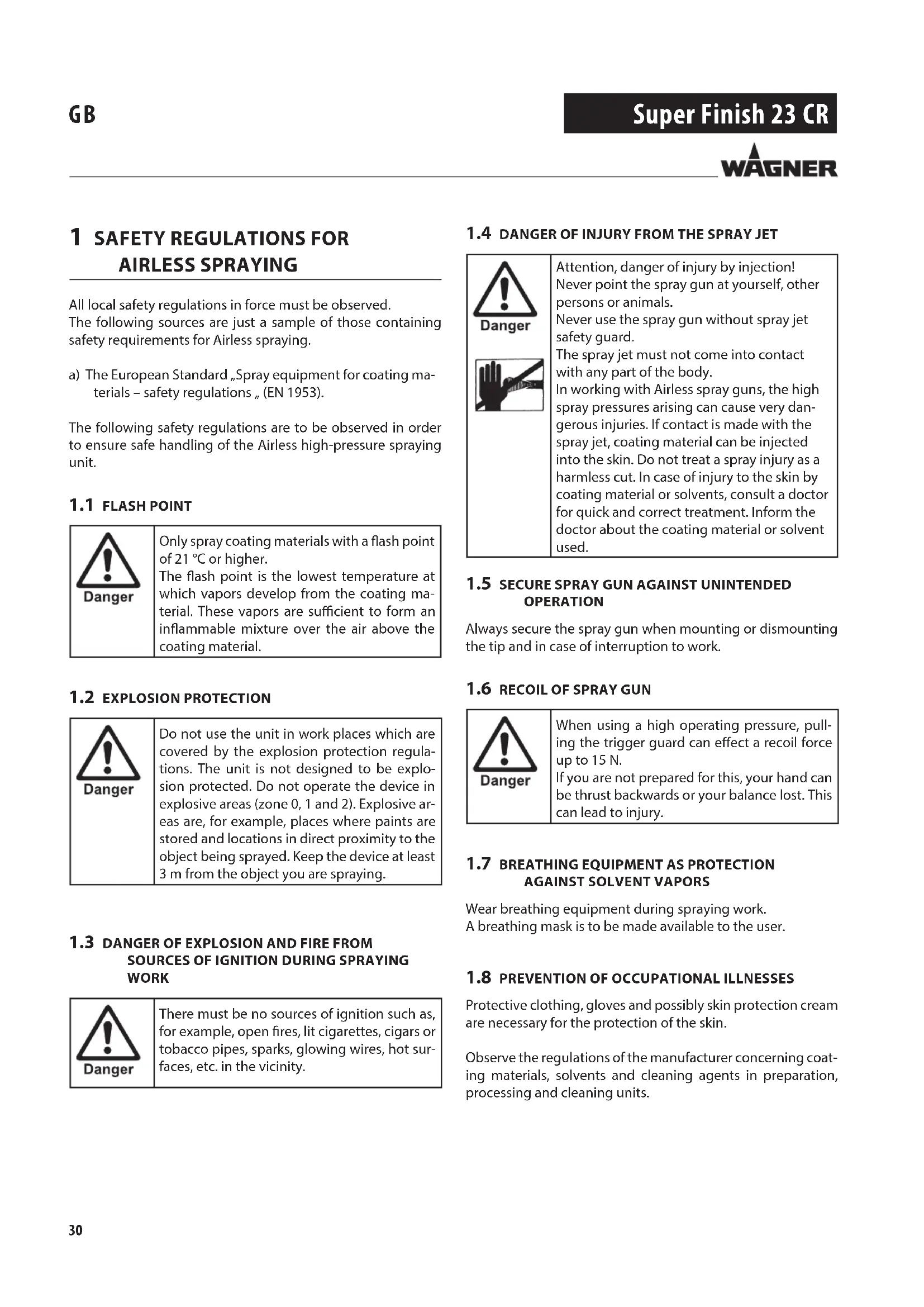
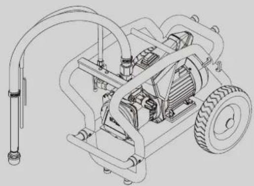
Super Finish 23 CR is an electric driven unit for the airless atomization of different painting materials. The Super Finish 23 CR is also great for processing injection foams and injection resin.
Super Finish 23 CR is made for jobs in the workshop and on the building site.
The unit performance is conceived so that its use is possible on building sites for small- to middle-area dispersion work.
When painting, the device is suitable for all kinds of typical painting jobs, e.g.:
doors, door frames, balustrades, furniture, woodencladding, fences, radiators (heating) and steel parts.
We recommend using the top container for paintwork.
2.2 COATING MATERIAL
Diluting lacquers and paints or those containing solvents, two-component coating materials, dispersion and latex paints. Injection foams (one and two-component) Injection resin (one and two-component)
| No other materials should be used for spraying without WAGNER's approval. |
| Pay attention to the Airless quality of the coating materials to be processed. |
The unit is able to process coating materials with up to 20,000 mPas. If highly viscous coating materials cannot be taken in or the performance of the unit is to low, the paint must be diluted in accordance with the manufacturer's instructions.
| Attention: Make sure, when stirring up with motor-driven agitators that no air bubbles are stirred in. Air bubbles disturb when spraying and can, in fact, lead to interruption of operation. |
2.2.1 COATING MATERIALS WITH SHARP-EDGED ADDITIONAL MATERIALS
These particles have a strong wear and tear effect on valves and tips, but also on the heating hose and spray gun. This impairs the durability of these wearing parts considerably.
2.2.2 FILTERING (FOR SPRAY WORK)
Sufficient filtering is required for fault-free operation. To this purpose the unit is equipped with a suction filter and an insertion filter in the spray gun. Regular inspection of these filters for damage or soiling is urgently recommended.
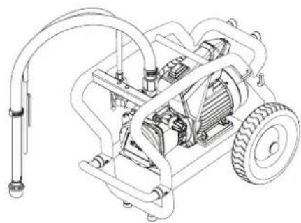
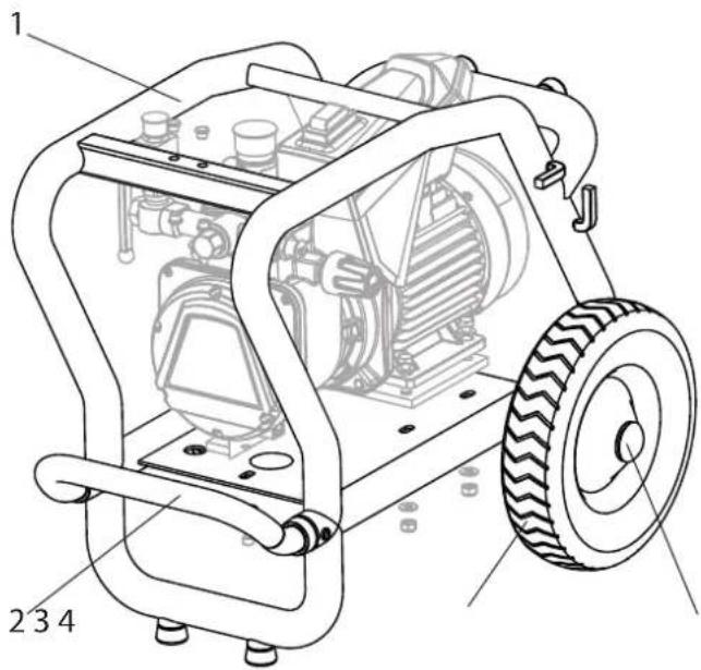
3. DESCRIPTION OF UNIT
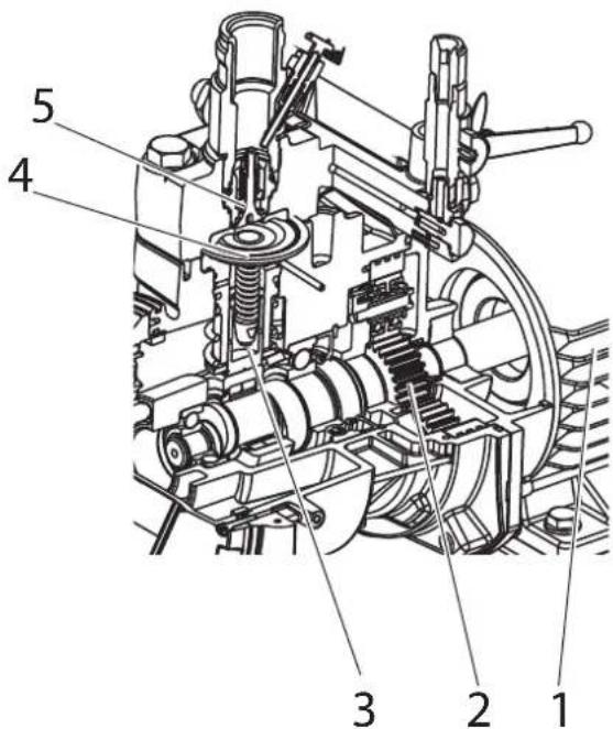
3.1 FUNCTIONING OF THE UNIT
The following section contains a brief description of the technical construction for better understanding of the function:
Super Finish 23 CR is an electrically driven high-pressure paint spraying equipment.
The electric motor (1) drives the hydraulic pump via planetary gears (2). A piston (3) is moved up and down so that hydraulic oil is moved under the diaphragm (4) which then moves.
In detail:
The downwards movement of the machine opens the disk inlet valve (5) automatically and coating material is sucked in.
During the upwards movement of the diaphragm, the coating material is displaced and the outlet valve opens while the inlet valve is closed.
The coating material flows under high pressure through the high-pressure hose to the gun.
The pressure control valve limits the set pressure in the hydraulic oil circuit and thus also the pressure of the coating material.
A pressure change when the same tip is used also leads to a change in the amount of paint atomized.
The Super Finish 23 CR can be used both horizontally and vertically.
a) Horizontal operation:
For use with a top tank or for direct suction with a flexible suction system.

b) vertical operation:
For direct intake with a rigid suction system.

3.3 EXPLANATORY DIAGRAM
1 Material ball cock:*
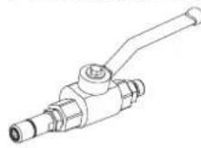
Open:
The material can be fed

Closed: The material cannot be fed
2 Whip hose for injection work (a)*
Tip guard with airless tip for spray work (b)*
3 Gun*
4 High-pressure hose
5 ON/OFF switch
6 Connection for high-pressure hose
7 Pressure control valve
8 Discharge tap to regulate the flow of the material:
Open (discharge tap points down):
The material is fed into the hopper/ material container

Closed (discharge tap at 90°):
The material is fed to the gun or to the material ball cock.
9 Return tube
10 Hopper*
11 Inlet valve button
12 Outlet valve
13 Oil measuring stick
14 Pressure gauge
15 Suction system* rigid (a) and flexible (b)
*Accessory. The actual scope of the delivery depends on how the Spray Pack is configured.


3.4 TECHNICAL DATA
Voltage : 230-240 V AC, 50 Hz
Fuses : 16 A time-lag
Unit connecting line : 6 m long, 3 x 1.5 mm 2
Max. current consumption: 7.0 A
Degree of protection : IP 54
Rated input of device: 1.3 kW
Max. operating pressure : 25 MPa (250 bar)
Max. volume flow : 2.6 l/min
Volume flow at 12 MPa
(120 bar) with water : 2.3 l/min
Max. temperature of the
coating material : 43 °C
Max. viscosity : 20,000 mPas
Empty weight 37 kg
Hydraulic oil filling
quantity :
Hydraulics housing 1.3 liter
Gears (grease) 45 g
Max. vibration at the spraygun : lower than 2.5 m/s 2
Max. sound pressure level: 75 dB (A)*
*Place of measurement: 1 m distance from unit and 1.60 m above floor, 12 MPa (120 bar) operating pressure, reverberant floor
4 STARTUP
4.1 GUN
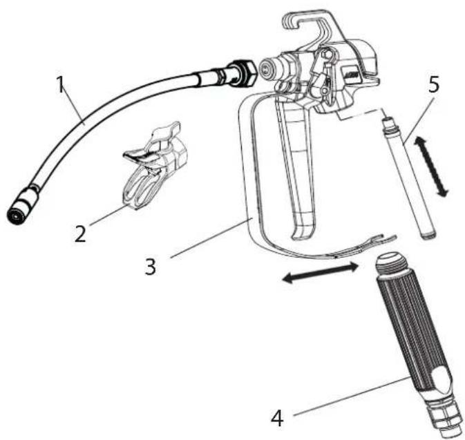
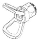
- Screw either the whip hose (1 for injection work) or the nozzle holder with nozzle (2 for spray work) to the gun.
| Before any injection work, remove the filter that is premounted in the gun, as described below, to prevent it from becoming blocked. |
- Pull the protective bracket (3) forwards.
- Screw the grip (4) out of the gun housing. Pull out the insertion filter (5).
- Screw the grip (4) into the gun housing and tighten it.
- Latch in the protective bracket (3).
4.2 HIGH PRESSURE HOSE AND PRESSURE GAUGE
| To check whether or not the hose is pressurized, the provided pressure gauge has to be secured to the high-pressure hose. |
- Screw the pressure gauge (11) to the hose connection (A) or to the gun (B).

- Screw the high pressure hose (9) onto the hose connection or the pressure gauge.
- Screw the gun (10) or the material ball cock onto the high pressure hose.
- Tighten all union nuts on high pressure hose so that no material can escape.

When unscrewing the high pressure hose, hold firmly on the hose connection with a 22mm wrench.
4.3 HOPPER
- Ensure that the sealing surfaces of the connections are clean. Ensure that the red inlet (1) is inserted in the coating material inlet (4).
- Screw the union nut (5) on the return pipe (6) onto the connection (7) (spanner width 22mm).
- Screw the upper hopper (8) onto the coating material inlet (4).

4.4 SUCTION SYSTEM
- Ensure that the sealing surfaces of the connections are clean. Ensure that the red inlet (1) is inserted in the coating material inlet (4).
- Use the enclosed 41 mm wrench to screw the union nut (2) at the suction hose (3) onto the coating material inlet (4) and tighten it.
- Screw the union nut (5) at the return hose (6) to the connection (7) (22mm).

4.5 CONNECTION TO THE MAINS NETWORK

Connection must always be carried out via an appropriately grounded safety outlet with residual-current-operated circuit-breaker.
Before connecting the unit to the mains supply, ensure that the line voltage matches that specified on the unit's rating plate.
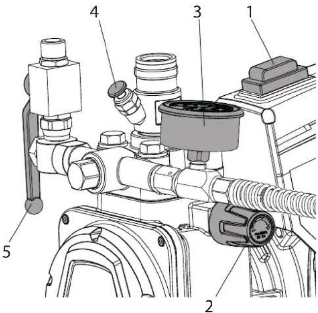
4.6 CLEANING PRESERVING AGENT WHEN STARTING-UP OF OPERATION INITIALLY
- Open the discharge tap (5).
- Pour suitable cleaning agent into the hopper or immerse the suction system in a container with suitable cleaning agent.
- Set ON/OFF switch (1) to ON; the unit commences to run.
- Turn the pressure regulating knob (2) to the right until the stop is reached.
- Wait until cleaning agent is emitted from the return hose.
- Turn the pressure regulating knob (2) back approx. one rotation.
- Close the discharge tap (5). Pressure is rising up inside the high pressure hose (visible at pressure gauge (3))
- Point the gun into an open collecting container and pull the trigger guard at the gun.
- The pressure is increased by turning the pressure regulating knob (2) to the right. Set approx. 10 MPa (100 bar) at the pressure gauge.
- Pump the cleaning agent out of the unit for approx. 1 - 2 min. (\~5 litres) into the open collecting container.
4.7 VENTILATE UNIT (HYDRAULIC SYSTEM) IF THE SOUND OF INLET VALVE IS NOT AUDIBLE
- Set ON/OFF switch (1) to ON.
- Turn pressure regulating knob (2) three revolutions to the left.
- The hydraulic system is ventilated. Leave the unit on for two to three minutes.
- Then turn pressure regulating knob (2) to the right until stop.
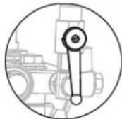
- Press inlet valve pusher (4).
Sound of the inlet valve is audible. - If not, repeat points 2 and 4
4.8 TAKING THE UNIT INTO OPERATION WITH COATING MATERIAL
- Open the discharge tap (5).
- Pour coating material into the hopper or dip the suction system into the material container.
- Press inlet valve pusher (4) several times to release possibly clogged inlet valve
- Set ON/OFF switch (1) to ON; the unit will start.
- Turn the pressure regulating knob (2) to the right until the stop is reached.
When the noise of the valves changes, the unit is bled and takes in coating material. - If coating material exits from the return hose, turn the pressure regulating knob (2) back approx. 1 rotation.
- Close the discharge tap (5). Pressure is rising up inside the high pressure hose (visible at pressure gauge (3)).
- Pull the trigger of the gun and spray into an open collecting container in order to remove the remaining cleaning agent from the unit. When coating materials exits, release the trigger.
- Adjust the pressure by turning the pressure regulating knob (2).
- The unit is ready for use.
5 TRANSPORTATION
Pull out the drawbar until it audibly engages.
To retract the drawbar press the two locking buttons (1).

Transportation in vehicle
Secure the unit in the vehicle by means of suitable fasteners. The device can be placed on its side if necessary. In this case, please ensure that no attachments can be damaged. Attention: Paint or solvent residues can escape from the connections!
6 HANDLING THE HIGH-PRESSURE HOSE
The unit is equipped with a high-pressure hose specially suited for diaphragm pumps.

Danger
Danger of injury through leaking high-pressure hose. Replace any damaged high-pressure hose immediately.
Never repair defective high-pressure hoses yourself!
The high-pressure hose is to be handled with care. Avoid sharp bends and folds: the smallest bending radius is about 20 cm.
Do not drive over the high-pressure hose. Protect against sharp objects and edges.
Never pull on the high-pressure hose to move the device.
Make sure that the high-pressure hose cannot twist. This can be avoided by using a Wagner spray gun with a swivel joint and a hose system.

When using the high-pressure hose while working on scaffolding, it is best to always guide the hose along the outside of the scaffolding.

The risk of damage rises with the age of the high-pressure hose.
Wagner recommends replacing high-pressure hoses after 6 years.

Only use WAGNER original-high-pressure hoses with internal heating in order to ensure functionality, safety and durability.
7 INTERRUPTION OF WORK

If using quick-drying or two-component coating materials, do not fail to rinse unit through with a suitable cleaning agent during the processing period. Follow for the relevant instructions in chapter 8.
- Open the discharge tap, then set the ON/OFF switch OFF.
- Pull the trigger on the gun or open the material ball cock to depressurize the high-pressure hose.
For spray work
- Secure the gun, refer to the operating manual of the gun.
- Remove tip from tip holder and store the tip in a small vessel with suitable cleaning agent.
8 CLEANING THE UNIT
A clean state is the best method of ensuring operation without problems. After you have finished work, clean the unit. Under no circumstances may coating material rests dry and harden in the unit. The cleaning agent used for cleaning (only with a flash point above 21 °C) must be suitable for the coating material used.

Warm water improves the cleaning effect in the case of water-dilutable coating materials.

For spray work: Secure the spray gun, refer to the operating manual of the spray gun. Remove and clean the tip.
- Open the discharge tap.
- Set ON/OFF switch to ON.
- Turn the pressure control valve back in order to set a minimal pressure.
Only for units with suction system: Remove suction system from material container, leave return hose in material container until hardly any material escapes. Immerse the suction system in a suitable cleaning agent.
- Close the discharge tap.
- Hold the gun or material ball valve/hose whip in an open bucket. Pull the trigger on the gun or open the material ball valve to pump out the remaining material (if appropriate, increase the pressure at the pressure control valve slowly in order to obtain a higher material flow).

Attention
The container must be earthed in case of coating materials which contain solvents.

Attention
Caution! Do not pump in a container with small opening (bunghole)!
See safety regulations.
- Release the trigger on the gun or close the material ball cock.
- Fill up hopper with suitable cleaning agent.
- Open the discharge tap.
- Pre-clean the hopper and filter with a brush.
- Pump suitable cleaning agent in the circuit for several minutes.
- Close the discharge tap
-
Hold the gun or material ball cock/whip hose in an open bucket. Pull the trigger on the gun or open the material ball cock to pump the cleaning agent out of the hopper. Do this by pulling and releasing the trigger on the gun several times/opening and closing the material ball cock.
-
Pour new detergent into the container and repeat the above procedure 1 or 2 times.
- Switch off unit
- Open the discharge tap.
8.1 CLEANING THE UNIT FROM THE OUTSIDE

Danger
First unplug the power plug from the outlet. Danger of short-circuits caused by water ingression! Never spray down the unit with high-pressure or high-pressure steam cleaners.

Danger
Do not put the high-pressure hose into solvents. Use only a wet cloth to wipe down the outside of the hose.
Wipe down unit externally with a cloth which has been immersed in a suitable cleaning agent.
8.2 SUCTION FILTER

Clean filters always ensure maximum volume, constant spray pressure and problem-free functioning of the unit.

Unit with suction system
- Unscrew the filter (Item 1) from the suction tube.
- Clean or replace the filter.
Carry out cleaning with a hard brush and a corresponding cleaning agent.
Unit with hopper
- Release screws with a screwdriver (Item 2).
- Lift and remove filter disk with a screwdriver
- Clean or replace the filter disk.
Carry out cleaning with a hard brush and a corresponding cleaning agent.
8.3 CLEANING THE AIRLESS SPRAY GUN
- Rinse the Airless spray gun with a suitable cleaning agent under lower operating pressure.
- Secure the spray gun, refer to the operating manual of the spray gun.
Remove and clean the tip. - Clean the tip thoroughly with a suitable cleaning agent so that no suitable coating material rests remain.
- Do not store the tip in solvent because this reduces the durability considerably.
- Clean the outside of the Airless spray gun thoroughly.

Insertion filter in the Airless spray gun
Removal
- Pull the protective bracket (1) forwards.
- Screw the grip (2) out of the gun housing. Pull out the insertion filter (3).
- If the insertion filter is clogged or defective, replace it.
Installation
- Slide the insertion filter (3) with the longer cone into the gun housing.
- Screw the grip (2) into the gun housing and tighten it.
- Latch in the protective bracket (1).
9 SERVICING
9.1 GENERAL SERVICING
 | We strongly recommend having an annual check carried out by technicians for safety reasons. Please observe all the applicable national regulations. |
 | You can servicing of the unit carried out by the Wagner Service. Favourable conditions can be agreed with a service agreement and/or maintenance packages. |
Minimum check before every startup:
- Check the high-pressure hose, gun with rotary joint, power supply cable with plug for damage.
- Check whether the pressure gauge can be read.
| When using two-component materials frequently, we recommend using a pressure measuring unit (art. no. 2353 487). |
Check at periodical intervals:
- Check inlet and outlet valve according wear. Clean it and replace worn out parts.
- Check all filter inserts (spray gun, hopper) clean it and replace if necessary.
9.2 HIGH-PRESSURE HOSE
Inspect the high-pressure hose visually for any notches or bulges, in particular at the transition in the fittings. It must be possible to turn the union nuts freely. A conductivity of less than
1 MΩ must exist across the entire length.
 Attention Attention | Have all the electric tests carried by the Wagner Service. |
 | The risk of damage rises with the age of the high-pressure hose.Wagner recommends replacing high-pressure hoses after 6 years. |
10 REPAIRS AT THE UNIT

Switch the unit off. Before all repair work: Unplug the power plug from the outlet.
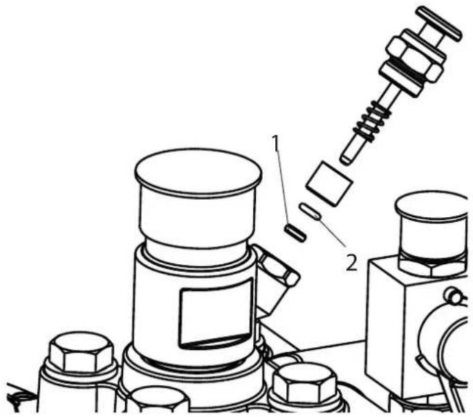
10.1 INLET VALVE PUSHER
- Use a 17 mm spanner to screw out the inlet valve button.
- Replace the wiper (1) and O-ring (2).
10.2 INLET VALVE
- Place the enclosed 30 mm wrench on the trigger housing (1).
- Loosen the trigger housing (1) with light blows of a hammer on the end of the wrench.
- Screw out the trigger housing with the inlet valve (2) from the paint section.
- Pull of the clasp (3) using the enclosed screwdriver.
- Place the enclosed 30 mm wrench on the inlet valve (2). Turn out the inlet valve carefully.
- Clean the valve seat (4) with a cleaning agent and brush (ensure that no brush hairs are left behind).
- Clean the seals (5, 6) and check for damage. Replace, if necessary.
- Check all the valve parts for damage. In case of visible wear replace the inlet valve.

Installation
- Insert the inlet valve (2) into the trigger housing (1) and secure with the clasp (3). Ensure that the (black) seal (5) is mounted in the trigger housing.
- Screw the unit from the trigger housing and the inlet valve into the paint section. The same (black) seal (6) has to be mounted in the paint section.
- Tighten the trigger housing with the 30 mm wrench and tighten with three light blows of the hammer on the end of the wrench. (Corresponds to approx. 90 Nm tightening torque).
10.3 OUTLET VALVE
- Use a 22 mm wrench to screw the outlet valve from the paint section.
- Carefully pull of the clasp (1) using the enclosed screw-driver. The compression spring (2) presses ball (4) and valve seat (5) out.
- Clean or replace the components.
- Check the O-ring (7) for damage.
- Check the installation position when mounting the spring support ring (3) (clipped onto spring (2)), outlet valve seat (5) and seal (6), refer to figure.

10.4 PRESSURE CONTROL VALVE
 Danger Danger | Only have the pressure control valve (1) replaced by the customer service.The max. operating pressure has to be reset by the customer service. |

10.5 TYPICAL WEAR PARTS
Inlet valve (spare part Order No.: 2393043)
For replacing refer to Section 10.2
(failure becomes noticeable through performance loss and/or poor or no suction)
Outlet valve (spare part Order No.: 2393106)
For replacing refer to Section 10.3
(failure becomes noticeable through performance loss and/or poor suction) The outlet valve is usually considerably more durable than the inlet valve. Thorough cleaning may already help here.
10.6 REMEDY IN CASE OF FAULTS
| TYPE OF MALFUNCTION W | WHAT ELSE? POSSIBLE CAUSE MEASURES FOR ELIMINATING THE MALFUNCTION | ||
| Unit does not start Indicating lamp does not illuminate | No voltage applied Check voltage supply | ||
| Indicating lamp illuminates | Unit fuse has triggered Let the motor cool down | ||
| Unit does not suck in Air bubbles do not exit at the return hose | Inlet valve clogged Press the inlet valve button until the stop is reached several times by hand | ||
| Inlet/outlet valve soiled / foreign bodies (e.g. threads) drawn in / worn | Remove the valves and clean then (-> refer to Section Pkt.10.2/10.3) / replace worn parts | ||
| Pressure control valve turned down completely | Turn the pressure control valve to the right until the stop is reached | ||
| Air bubbles exit from the return hose | Unit is sucking in outside air | Check: Inlet valve button leaky? -> Replace wiper and O-ring (-> refer to Section 10.1) The red entry is missing in the coating material entrance (-> see 4.3) | |
| Unit does not generate pressure | Unit has sucked in Air in the oil circuit Bleed the oil circuit in the unit by turning the pressure control valve completely to the left (until overturning) and let it run approx. 2 - 3 min. Then turn the pressure control valve to the right and set the pressure (repeat process several times, if necessary). | ||
| Not enough oil | Check the oil level | ||
| Pressure collapses during work (this can be seen on the pressure gauge) | Suction filter clogged | Check the suction filter. If necessary, clean, replace or remove | |
| Paint cannot be worked in this state. Due to its properties the paint clogs the valves (inlet valve) and the delivery rate is too low. | Dilute the paint | ||
| Unit reached pressure, but the pressure collapses during spraying. pressure gage still shows high pressure | Clogged filter do not let enough paint pass | Check/clean the gun filter | |
| Tip clogged | Clean the tip (-> refer to Section 10.1) | ||
| Unit does not generate the max. pressure possible. Even though the discharge tap is closed, material still emerges from the return flow hose. | Discharge tap defective | Please contact Wager Customer Service | |
| No material is fed (in injection work) | The pressure gauge indicates pressure | The gun filter has not been removed and is blocked | Remove gun filter (-> refer to Section 4.1) |
11 SPARE PARTS AND ACCESSORIES
11.1 SUPER FINISH 23 CR ACCESSORIES
Accessories:
| ITEM DESIGNATION ORDER NO. | ||
| 1 Spray gun AG-14(stainless steel) | 0502081A | |
| 2 Whip hose 0097 057 | ||
| 3 Adapter G to F thread 2405153 | ||
| 4 HP ball cock with mouth piece (1/4"NPSM) | 2353 754 | |
| 5 HP ball cock with whip hose and slide coupling (1/4"NPSM) | 2353 789 | |
| 6 HP ball cock with whip hose and mouth piece (1/4"NPSM) | 2353 788 | |
| 7 Hopper 5l 2357 506 | ||
| 8 Pressure measuring unit 400 bar 2353 487 | ||
| 9 Tip extensionLength 15 cmLength 30 cmLength 45 cmLength 60 cm | 0556 0740556 0750556 0760556 077 | |
| 10 Suction system (flexible) 2393123 | ||
| ITEM DESIGNATION ORDER NO. | ||
| 11 Suction system (rigid) 2405950 | ||
| 12 Hose reel HR 45, 30m 341912 | ||
| HP hose DN-6; 15 m | 9984 574 | |
| HP hose DN-6; 6 m(for injection work) | 2351 983 | |
| Intake system C-coupling 1.4 m | 97082 | |
| Intake system C-coupling 3.5 m | 97083 | |
| Reducing double nipple 1/4“NPSM | 34038 | |
| TipClean 200 ml | 2400214 | |
| TipClean 1L | 2400216 | |
| Hydraulic oil Divinol HVI 15 1 L | 21061 | |
| EasyClean 1 L | 2412656 | |
HEA NOZZLES FOR LOW-MIST SPRAYING AT LOW PRESSURE

HEA stands for High Efficiency Airless, an innovative nozzle technology revolutionising airless spraying. HEA nozzles allow the pressure of the spray device to be reduced right down and allow it to work in the low-pressure range (ideally at 80 - 140 bar). The nozzles can be used with all TradeTip 3 nozzle holders and WAGNER devices.
Some paints may need to be diluted to achieve the best result possible. The experts at Wagner application technology have therefore tested a wide range of materials for you. Their recommendations can be found in the Wagner Spray Guide at sprayguide.wagner-group.com.
Set the low pressure in the HEA range and start.

Even spray pattern without spray edges.
If edges are visible, slowly increase the pressure.
HEA tip table

All of the tips in the table below are supplied together with the appropriate gun fi Iter.
| Application Tip marking Spray | angle | Bore inch / mm | Spraying width mm 1) | Gun fi Iter Order no. | ||
| Synthetic-resin paints | 211 | 20 ° | 0.011 / 0.28 | 120 | red | 0554211 |
| PVC paints | 311 | 30 ° | 0.011 / 0.28 | 150 | red | 0554311 |
| 411 | 40 ° | 0.011 / 0.28 | 190 | Rot | 0554411 | |
| Paints, primers | 213 | 20 ° | 0.013 / 0.33 | 120 | red | 0554213 |
| Fillers | 313 | 30 ° | 0.013 / 0.33 | 150 | red | 0554313 |
| 413 | 40 ° | 0.013 / 0.33 | 190 | red | 0554413 | |
| Fillers | 415 | 40 ° | 0.015 / 0.38 | 190 | yellow | 0554415 |
| Rust protection paints | 515 | 50 ° | 0.015 / 0.38 | 225 | yellow | 0554515 |
| 615 | 60 ° | 0.015 / 0.38 | 270 | yellow | 0554615 | |
| Rust protection paints | 417 | 40 ° | 0.017 / 0.43 | 190 | white | 0554417 |
| Latex paints | 517 | 50 ° | 0.017 / 0.43 | 225 | white | 0554517 |
| Dispersions | 617 | 60 ° | 0.017 / 0.43 | 270 | white | 0554617 |
| Rust protection paints | 519 | 50 ° | 0.019 / 0.48 | 225 | white | 0554519 |
| Latex paints | 619 | 60 ° | 0.019 / 0.48 | 270 | white | 0554619 |
| Dispersions | ||||||
| Flame retardant 421 | 40 ° | 0.021 / 0.53 | 190 | white | 0554421 | |
| 521 | 50 ° | 0.021 / 0.53 | 225 | white | 0554521 | |
| 621 | 60 ° | 0.021 / 0.53 | 270 | white | 0554621 | |
1) Spray width at about 30 cm to the object and 100 bar (10 MPa) pressure with synthetic-resin paint 20 DIN seconds.
Airless tip table
Wagner
TradeTip 3 tip
up to 270 bar
(27 MPa)
without tip
G thread (7/8 - 14 UN)
Order no. 0289390

All of the tips in the table below are supplied together with the appropriate gun fi iter.
| Application Tip marking Spray | angle | Bore inch / mm | Spraying width mm 1) | Gun fi Iter Order no. | ||
| Water-thinnable and solvent-based paints and varnishes, oils, separating agents | 107 | 10° | 0.007/0.18 | 100 | red | 0553107 |
| 207 | 20° | 0.007/0.18 | 120 | red | 0553207 | |
| 307 | 30° | 0.007/0.18 | 150 | red | 0553307 | |
| 407 | 40° | 0.007/0.18 | 190 | red | 0553407 | |
| 109 | 10° | 0.009/0.23 | 100 | red | 0553109 | |
| 209 | 20° | 0.009/0.23 | 120 | red | 0553209 | |
| 309 | 30° | 0.009/0.23 | 150 | red | 0553309 | |
| 409 | 40° | 0.009/0.23 | 190 | red | 0553409 | |
| 509 | 50° | 0.009/0.23 | 225 | red | 0553509 | |
| 609 | 60° | 0.009/0.23 | 270 | red | 0553609 | |
| Synthetic-resin paintsPVC paints | 111 | 10° | 0.011/0.28 | 100 | red | 0553111 |
| 211 | 20° | 0.011/0.28 | 120 | red | 0553211 | |
| 311 | 30° | 0.011/0.28 | 150 | red | 0553311 | |
| 411 | 40° | 0.011/0.28 | 190 | red | 0553411 | |
| 511 | 50° | 0.011/0.28 | 225 | red | 0553511 | |
| 611 | 60° | 0.011/0.28 | 270 | red | 0553611 | |
| Paints, primersFillers | 113 | 10° | 0.013/0.33 | 100 | red | 0553113 |
| 213 | 20° | 0.013/0.33 | 120 | red | 0553213 | |
| 313 | 30° | 0.013/0.33 | 150 | red | 0553313 | |
| 413 | 40° | 0.013/0.33 | 190 | red | 0553413 | |
| 513 | 50° | 0.013/0.33 | 225 | red | 0553513 | |
| 613 | 60° | 0.013/0.33 | 270 | red | 0553613 | |
| 813 | 80° | 0.013/0.33 | 330 | red | 0553813 | |
| FillersRust protection paints | 115 | 10° | 0.015/0.38 | 100 | yellow | 0553115 |
| 215 | 20° | 0.015/0.38 | 120 | yellow | 0553215 | |
| 315 | 30° | 0.015/0.38 | 150 | yellow | 0553315 | |
| 415 | 40° | 0.015/0.38 | 190 | yellow | 0553415 | |
| 515 | 50° | 0.015/0.38 | 225 | yellow | 0553515 | |
| 615 | 60° | 0.015/0.38 | 270 | yellow | 0553615 | |
| 715 | 70° | 0.015/0.38 | 300 | yellow | 0553715 | |
| 815 | 80° | 0.015/0.38 | 330 | yellow | 0553815 | |
| Rust protection paintsLatex paintsDispersions | 117 | 10° | 0.017/0.43 | 100 | white | 0553117 |
| 217 | 20° | 0.017/0.43 | 120 | white | 0553217 | |
| 317 | 30° | 0.017/0.43 | 150 | white | 0553317 | |
| 417 | 40° | 0.017/0.43 | 190 | white | 0553417 | |
| 517 | 50° | 0.017/0.43 | 225 | white | 0553517 | |
| 617 | 60° | 0.017/0.43 | 270 | white | 0553617 | |
| 717 | 70° | 0.017/0.43 | 300 | white | 0553717 | |
| 817 | 80° | 0.017/0.43 | 330 | white | 0553817 | |
| Rust protection paintsLatex paintsDispersions | 219 | 20° | 0.019/0.48 | 120 | white | 0553219 |
| 319 | 30° | 0.019/0.48 | 150 | white | 0553319 | |
| 419 | 40° | 0.019/0.48 | 190 | white | 0553419 | |
| 519 | 50° | 0.019/0.48 | 225 | white | 0553519 | |
| 619 | 60° | 0.019/0.48 | 270 | white | 0553619 | |
| 719 | 70° | 0.019/0.48 | 300 | white | 0553719 | |
| 819 | 80° | 0.019/0.48 | 330 | white | 0553819 | |
| 919 | 90° | 0.019/0.48 | 385 | white | 0553919 | |
| Flame retardant 221 | 20° | 0.021/0.53 | 120 | white | 0553221 | |
| 321 | 30° | 0.021/0.53 | 150 | white | 0553321 | |
| 421 | 40° | 0.021/0.53 | 190 | white | 0553421 | |
| 521 | 50° | 0.021/0.53 | 225 | white | 0553521 | |
| 621 | 60° | 0.021/0.53 | 270 | white | 0553621 | |
| 721 | 70° | 0.021/0.53 | 300 | white | 0553721 | |
| 821 | 80° | 0.021/0.53 | 330 | white | 0553821 | |
1) Spray width at about 30 cm to the object and 100 bar (10 MPa) pressure with synthetic-resin paint 20 DIN seconds.

All of the tips in the table below are supplied together with the appropriate gun fi Iter.
| Application Tip marking Spray | angle | Bore inch / mm | Spraying width mm 1) | Gun fi Iter Order no. | ||
| Roof coatings 223 | 20° | 0.023 / 0.58 | 120 | white | 0553223 | |
| 323 | 30° | 0.023 / 0.58 | 150 | white | 0553323 | |
| 423 | 40° | 0.023 / 0.58 | 190 | white | 0553423 | |
| 523 | 50° | 0.023 / 0.58 | 225 | white | 0553523 | |
| 623 | 60° | 0.023 / 0.58 | 270 | white | 0553623 | |
| 723 | 70° | 0.023 / 0.58 | 300 | white | 0553723 | |
| 823 | 80° | 0.023 / 0.58 | 330 | white | 0553823 | |
| Thick-fi Im materials, Corrosion protection Spray fi ller | 225 | 20° | 0.025 / 0.64 | 120 | white | 0553225 |
| 325 | 30° | 0.025 / 0.64 | 150 | white | 0553325 | |
| 425 | 40° | 0.025 / 0.64 | 190 | white | 0553425 | |
| 525 | 50° | 0.025 / 0.64 | 225 | white | 0553525 | |
| 625 | 60° | 0.025 / 0.64 | 270 | white | 0553625 | |
| 725 | 70° | 0.025 / 0.64 | 300 | white | 0553725 | |
| 825 | 80° | 0.025 / 0.64 | 330 | white | 0553825 | |
| 227 | 20° | 0.027 / 0.69 | 120 | white | 0553227 | |
| 327 | 30° | 0.027 / 0.69 | 150 | white | 0553327 | |
| 427 | 40° | 0.027 / 0.69 | 190 | white | 0553427 | |
| 527 | 50° | 0.027 / 0.69 | 225 | white | 0553527 | |
| 627 | 60° | 0.027 / 0.69 | 270 | white | 0553627 | |
| 827 | 80° | 0.027 / 0.69 | 330 | white | 0553827 | |
| 229 | 20° | 0.029 / 0.75 | 120 | white | 0553229 | |
| 329 | 30° | 0.029 / 0.75 | 150 | white | 0553329 | |
| 429 | 40° | 0.029 / 0.75 | 190 | white | 0553429 | |
| 529 | 50° | 0.029 / 0.75 | 225 | white | 0553529 | |
| 629 | 60° | 0.029 / 0.75 | 270 | white | 0553629 | |
| 231 | 20° | 0.031 / 0.79 | 120 | white | 0553231 | |
| 331 | 30° | 0.031 / 0.79 | 150 | white | 0553331 | |
| 431 | 40° | 0.031 / 0.79 | 190 | white | 0553431 | |
| 531 | 50° | 0.031 / 0.79 | 225 | white | 0553531 | |
| 631 | 60° | 0.031 / 0.79 | 270 | white | 0553631 | |
| 731 | 70° | 0.031 / 0.79 | 300 | white | 0553731 | |
| 831 | 80° | 0.031 / 0.79 | 330 | white | 0553831 | |
| 233 | 20° | 0.033 / 0.83 | 120 | white | 0553233 | |
| 333 | 30° | 0.033 / 0.83 | 150 | white | 0553333 | |
| 433 | 40° | 0.033 / 0.83 | 190 | white | 0553433 | |
| 533 | 50° | 0.033 / 0.83 | 225 | white | 0553533 | |
| 633 | 60° | 0.033 / 0.83 | 270 | white | 0553633 | |
| 235 | 20° | 0.035 / 0.90 | 120 | white | 0553235 | |
| 335 | 30° | 0.035 / 0.90 | 150 | white | 0553335 | |
| 435 | 40° | 0.035 / 0.90 | 190 | white | 0553435 | |
| 535 | 50° | 0.035 / 0.90 | 225 | white | 0553535 | |
| 635 | 60° | 0.035 / 0.90 | 270 | white | 0553635 | |
| 735 | 70° | 0.035 / 0.90 | 300 | white | 0553735 | |
| 439 | 40° | 0.039 / 0.99 | 190 | white | 0553439 | |
| 539 | 50° | 0.039 / 0.99 | 225 | white | 0553539 | |
| 639 | 60° | 0.039 / 0.99 | 270 | white | 0553639 | |
| Heavy duty applications | 243 | 20° | 0.043 / 1.10 | 120 | green | 0553243 |
| 443 | 40° | 0.043 / 1.10 | 190 | green | 0553443 | |
| 543 | 50° | 0.043 / 1.10 | 225 | green | 0553543 | |
| 643 | 60° | 0.043 / 1.10 | 270 | green | 0553643 | |
| 445 | 40° | 0.045 / 1.14 | 190 | green | 0553445 | |
| 545 | 50° | 0.045 / 1.14 | 225 | green | 0553545 | |
| 645 | 60° | 0.045 / 1.14 | 270 | green | 0553645 | |
| 451 | 40° | 0.051 / 1.30 | 190 | green | 0553451 | |
| 551 | 50° | 0.051 / 1.30 | 225 | green | 0553551 | |
| 651 | 60° | 0.051 / 1.30 | 270 | green | 0553651 | |
| 252 | 20° | 0.052 / 1.32 | 120 | green | 0553252 | |
| 455 | 40° | 0.055 / 1.40 | 190 | green | 0553455 | |
| 555 | 50° | 0.055 / 1.40 | 225 | green | 0553555 | |
| 655 | 60° | 0.055 / 1.40 | 270 | green | 0553655 | |
| 261 | 20° | 0.061 / 1.55 | 120 | green | 0553261 | |
| 461 | 40° | 0.061 / 1.55 | 190 | green | 0553461 | |
| 561 | 50° | 0.061 / 1.55 | 225 | green | 0553561 | |
| 661 | 60° | 0.061 / 1.55 | 270 | green | 0553661 | |
| 263 | 20° | 0.063 / 1.60 | 120 | green | 0553263 | |
| 463 | 40° | 0.063 / 1.60 | 190 | green | 0553463 | |
| 565 | 50° | 0.065 / 1.65 | 225 | green | 0553565 | |
| 665 | 60° | 0.065 / 1.65 | 270 | green | 0553665 | |
| 267 | 20° | 0.067 / 1.70 | 120 | green | 0553267 | |
| 467 | 40° | 0.067 / 1.70 | 190 | green | 0553467 |
1) Spray width at about 30 cm to the object and 100 bar (10 MPa) pressure with synthetic-resin paint 20 DIN seconds.
TEMPSPRAY
The paint material is heated to the required temperature uniformly by an electric heating element, which is located inside the hose (regulated from 20°C to 60°C).
Advantages:
- Constant paint temperature even at low outside temperatures
- Considerably better working of high viscosity coating materials
- Increased application efficiency
• Savings in solvents due to reduction in viscosity
• Adaptable to all airless units
| Order No. Description | |
| 23116602311853 | TempSpray H 226 (ideal for dispersions/materials with high viscosity)Basic unit 1/4" incl. Hose reel, heated hose DN10, 15m, hose 1/4" DN4, 1mSpraypack consisting of: Basic unit (2311660), Airless un AG 14 G thread, incl. Trade Tip 3 nozzle holder and 2SpeedTip D10 (111/419) |
| 23116612311854 | TempSpray H 326 (ideal for dispersions/materials with high viscosity)Basic unit 1/4" incl. Hose reel, heated hose DN10, 30m, hose 1/4" DN4, 1mSpraypack consisting of: Basic unit (2311661), Airless un AG 14 G thread, incl. Trade Tip 2 nozzle holder and 2SpeedTip D20 (115/421) |
11.2 SPARE PARTS LIST SUPER Finish 23 CR
| ITEM ORDER-NO DESIGNATION | |
| 1 2391208 Protective cap | |
| 2 2369454 | Inlet |
| 3 2422746 Inlet valve housing | |
| 4 2393043 Inlet valve assy. | |
| 5 2369458 Sealing ring (1 pc.) | |
| 6 2398994 Label Wagner (right) | |
| 7 2393044 Oil cap screw kpl. assy. | |
| 8 2422749 | Discharge tap assy. |
| 9 2415593 Banjo bolt | |
| ITEM | ORDER-NO DESIGNATION |
| 10 24 | 17151 Sealing ring (1 pc.) |
| 11 | 2382401 Cylindrical pin (1 pc.) |
| 12 | 2422747 Outlet valve housing assy. |
| 13 | 2393106 Outlet valve assy. |
| 14 23 | 93105 O-ring and sealing ring |
| 15 24 | 16965 Label SF 23 CR |
| 16 23 | 69436 Reducing double nipple |
| 17 23 | 91210 Protective cap |
| 18 23 | 98998 Label Wagner (left) |

Spare parts diagram trolley Super Finish 23 CR
TESTING OF THE UNIT
For safety reasons, we would recommend having the device checked by an expert as required but at least every 12 months to ensure that it can continue to operate safely.
In the case of unused devices, the check can be postponed until they are next started up.
All (potentially deviating) national inspection and maintenance regulations must also be observed.
If you have any questions, please contact the customer service team at Wagner.
IMPORTANT INFORMATION ON PRODUCT LIABILITY
According to an EU directive, the manufacturer is only liable without limitation for faults in the product if all parts come from the manufacturer or have been approved by the manufacturer and have been mounted to the device and are operated properly. If third-party accessories or spare parts are used, the manufacturer is exonerated wholly or partly from his/her liability if use of the third-party accessories or spare parts have caused a defect in the product. In extreme cases, the relevant authorities can completely prohibit using the entire device.
With original WAGNER accessories and spare parts, compliance with all safety regulations is guaranteed.
NOTE ON DISPOSAL
In observance of the European Directive 2002/96/EC on waste electrical and electronic equipment and implementation in accordance with national law, this product is not to be disposed of together with household waste material but must be recycled in an environmentally friendly way!

Wagner or one of our dealers will take back your used Wagner waste electrical or electronic equipment and will dispose of it for you in an environmentally friendly way. Please ask your local Wagner service centre or dealer for details or contact us direct.
GUARANTEE DECLARATION
(Status 01.02.2009)
1. Scope of guarantee
All Wagner professional colour application devices (hereafter referred to as products) are carefully inspected, tested and are subject to strict checks under Wagner quality assurance. Wagner exclusively issues extended guarantees to commercial or professional users (hereafter referred to as “customer”) who have purchased the product in an authorised specialist shop, and which relate to the products listed for that customer on the Internet under www.wagner-group.com/profi-guarantee.
The buyer's claim for liability for defects from the purchase agreement with the seller as well as statutory rights are not impaired by this guarantee.
We provide a guarantee in that we decide whether to replace or repair the product or individual parts, or take the device back and reimburse the purchase price. The costs for materials and working hours are our responsibility. Replaced products or parts become our property.
2. Guarantee period and registration
The guarantee period amounts to 36 months. For industrial use or equal wear, such as shift operations in particular, or in the event of rentals it amounts to 12 months.
Systems driven by petrol or air are also guaranteed for a 12 month period.
The guarantee period begins with the day of delivery by the authorised specialist shop. The date on the original purchase document is authoritative.
For all products bought in authorised specialist shops from 01.02.2009 the guarantee period is extended to 24 months providing the buyer of these devices registers in accordance with the following conditions within 4 weeks of the day of delivery by the authorised specialist shop.
Registration can be completed on the Internet under www.wagner-group.com/profi-guarantee.
The guarantee certificate is valid as confirmation, as is the original purchase document that carries the date of the purchase. Registration is only possible if the buyer is in agreement with having the data being stored that is entered during registration.
When services are carried out under guarantee the guarantee period for the product is neither extended nor renewed.
Once the guarantee period has expired, claims made against the guarantee or from the guarantee can no longer be enforced.
3. Handling
If defects can be seen in the materials, processing or performance of the device during the guarantee period, guarantee
claims must be made immediately, or at the latest within a period of 2 weeks.
The authorised specialist shop that delivered the device is entitled to accept guarantee claims. Guarantee claims may also be made to the service centres named in our operating instructions. The product has to be sent without charge or presented together with the original purchase document that includes details of the purchase date and the name of the product. In order to claim for an extension to the guarantee, the guarantee certificate must be included.
The costs as well as the risk of loss or damage to the product in transit or by the centre that accepts the guarantee claims or who delivers the repaired product, are the responsibility of the customer.
4. Exclusion of guarantee
Guarantee claims cannot be considered
-for parts that are subject to wear and tear due to use or other natural wear and tear, as well as defects in the product that are a result of natural wear and tear, or wear and tear due to use. This includes in particular cables, valves, packaging, jets, cylinders, pistons, means-carrying housing components, filters, pipes, seals, rotors, stators, etc. Damage due to wear and tear that is caused in particular by sanded coating materials, such as dispersions, plaster, putty, adhesives, glazes, quartz foundation.
-in the event of errors in devices that are due to non-compliance with the operating instructions, unsuitable or unprofessional use, incorrect assembly and/or commissioning by the buyer or by a third party, or utilisation other than is intended, abnormal ambient conditions, unsuitable coating materials, unsuitable operating conditions, operation with the incorrect mains voltage supply/frequency, over-operation or defective servicing or care and/or cleaning.
-for errors in the device that have been caused by using accessory parts, additional components or spare parts that are not original Wagner parts.
-for products to which modifications or additions have been carried out.
-for products where the serial number has been removed or is illegible
-for products to which attempts at repairs have been carried out by unauthorised persons.
-for products with slight deviations from the target properties, which are negligible with regard to the value and usability of the device.
-for products that have been partially or fully taken apart.
5. Additional regulations.
The above guarantees apply exclusively to products that have been bought by authorised specialist shops in the EU, CIS, Australia and are used within the reference country.
If the check shows that the case is not a guarantee case, repairs are carried out at the expense of the buyer.
The above regulations manage the legal relationship to us concludingly. Additional claims, in particular for damages and losses of any type, which occur as a result of the product or its use, are excluded from the product liability act except with regard to the area of application.
Claims for liability for defects to the specialist trader remain unaffected.
German law applies to this guarantee. The contractual language is German. In the event that the meaning of the German and a foreign text of this guarantee deviate from one another, the meaning of the German text has priority.
J. Wagner GmbH
Division Professional Finishing
Otto Lilienthal Strasse 18
88677 Markdorf
Federal Republic of Germany
Subject to modifications · Printed in Germany
EU Declaration of conformity
We declare under sole responsibility that this product conforms to the following relevant stipulations: 2006/42/EC, 2014/30/EU, 2011/65/EU, 2012/19/EU
Applied harmonised norms:
EN 12621, EN ISO 12100, EN 1953, EN 60204-1, EN 61000-3-2, EN 61000-3-11, EN 61000-6-1, EN 61000-6-3
The EU declaration of conformity is enclosed with the product.
If required, it can be re-ordered using order number 2418310.
3.3 ILLUSTRATIONS DU MATÉRIEL

3.4 CARACTÉRISTIQUES TECHNIQUES
Tension: 230-240 volts \~, 50 Hz
Fusible: 16 A lent
4.2 TUYAU FLEXIBLE HAUTE PRESSION ET MANOMÈTRE

B

4.4 SYSTÈME D'ASPIRATION
4.5 RACCORDEMENT AU RÉSEAU ÉLECTRIQUE

4.8 MISE EN SERVICE DE L'APPAREIL AVEC LE PRODUIT DE REVÊTEMENT
10.2 VANNE D'ASPIRATION
Montage
10.4 VANNE DE RÉGLAGE DE PRESSION

10.5 PIÈCES D'USURE TYPIQUES
11.2 LISTE DE PIÈCES DE RECHANGE SUPER Finish 23 CR
11.3 LISTE DE PIÈCES DE RECHANGE DU CHARIOT
| N° RÉFÉRENCE DÉSIGNATION | |
| 1 2415521 Chariot compl. (réf. 2-4 comprise) | |
| 2 2402496 Timon compl.. | |
| 3 2402494 Roue (1 pce.) | |
| 4 9994950 Capuchon de roue (1 pce.) |
INDICATION DE MISE AU REBUT
Division Professional Finishing
Otto Lilienthal Strasse 18
88677 Markdorf
3.3 Figure illustrative
3.4 Dati tecnici
4 MESSA IN SERVIZIO 86
4.1 Aerografo 86
2 PANORAMICA SULL'IMPIEGO
3.2 FUNZIONAMENTO A DUE POSIZIONI
3.3 FIGURE ILLUSTRATIVE

3.4 DATITECNICI
Tensione: 230-240 V AC, 50 Hz
Corrente assorbita max.: 7,0 A
4.2 TUBO FLESSIBILE AD ALTA PRESSIONE E MANOMETRO

4.5 ALLACCIAMENTO ALLA RETE ELETTRICA
4.8 MESSA IN FUNZIONE DELL'APPARECCHIO CON MATERIALE
10.2 VALVOLA DI ENTRATA
Montaggio
10.4 VALVOLA REGOLATRICE DELLA PRESSIONE

10.5 TIPICI COMPONENTI DI USURA
11 RICAMBI ED ACCESSORI
11.1 ACCESSORI PER SUPER FINISH 23 CR

Accessori
11.2 ELENCO DEI RICAMBI SUPER Finish 23 CR
11.3 ELENCO DEI RICAMBI PER IL CARRELLO
| POS. N° ORD. NOME | |
| 1 2415521 | Carrello compl. (incl. pos. 2-4) |
| 2 2402496 Manubrio compl. | |
| 3 2402494 Ruota (1 pz.) | |
| 4 9994950 Coppa coprimozzo (1 pz.) |
11.4 ELENCO DEI RICAMBI CONTENITORE SUPERIORE
Division Professional Finishing
Otto Lilienthal Strasse 18
88677 Markdorf
Установка
10.3 BYIYCKHOB KLAIPAN
10.6 ТИПОВЫЕ ИЗНАШИВАЕМЫЕ ЧАСТИ


- Super finish 23 CR
- Airless high-pressure spraying unit originalbetriebsanleitung
- 10 Reparaturen am gerät 15
- 1.2 Explosionsschutz
- Vertikalbetrieb
- 4.4 Ansaugsystem
- 10 Reparaturen am gerät
- 10.2 Einlassventil
- Montage
- 10.4 Druckregelventil
- Prüfung des gerätes
- Translation of the original operating instructions
- Warning
- Ensure safety
- Contents
- 1 Safety regulations for airless spraying 30
- 2 General view of application 32
- Description of unit 33
- 4 Startup 35
- 5 Transportation 38
- 6 Handling the high-pressure hose 38
- 7 Interruption of work 38
- 8 Cleaning the unit 39
- 9 Servicing 40
- 10 Repairs at the unit 41
- 11 Spare parts and accessories 44
- 1 Safety regulations for airless spraying
- 1.1 Flash point
- 1.2 Explosion protection
- 1.3 Danger of explosion and fire from sources of ignition during spraying work
- 1.4 Danger of injury from the spray jet
- 1.6 Recoil of spray gun
- 1.7 Breathing equipment as protection against solvent vapors
- 1.8 Prevention of occupational illnesses
- 1.10 High-pressure hose
- 1.11 Electrostatic charging (formation of sparks or flames)
- 1.12 USE of units on building sites and workshops
- 1.13 Ventilation when spraying in rooms
- 1.14 Suction installations
- 1.15 Earthing of the object
- 1.16 Cleaning the unit with solvents
- 1.17 Cleaning the unit
- 1.18 Work or repairs at the electrical equipment
- 1.19 Work at electrical components
- 1.20 Setup on an uneven surface
- 2 General view of application
- 2.1 Application
- 2.2 Coating material
- 2.2.1 Coating materials with sharp-edged additional materials
- 2.2.2 Filtering (for spray work)
- Description of unit
- 3.1 Functioning of the unit
- Horizontal operation
- Vertical operation
- 3.3 Explanatory diagram
- 3.4 Technical data
- 4 Startup
- 4.1 GUN
- 4.2 High pressure hose and pressure gauge
- 4.3 Hopper
- 4.4 Suction system
- 4.5 Connection to the mains network
- 4.6 Cleaning preserving agent when starting-up of operation initially
- 4.7 Ventilate unit (hydraulic system) if the sound of inlet valve is not audible
- 4.8 Taking the unit into operation with coating material
- 5 Transportation
- Transportation in vehicle
- 6 Handling the high-pressure hose
- 7 Interruption of work
- For spray work
- 8 Cleaning the unit
- 8.1 Cleaning the unit from the outside
- 8.2 Suction filter
- 8.3 Cleaning the airless spray gun
- Insertion filter in the airless spray gun
- Removal
- Installation
- 9 Servicing
- 9.1 General servicing
- Minimum check before every startup
- Check at periodical intervals
- 9.2 High-pressure hose
- 10 Repairs at the unit
- 10.1 Inlet valve pusher
- 10.2 Inlet valve
- 10.3 Outlet valve
- 10.4 Pressure control valve
- 10.5 Typical wear parts
- 11 Spare parts and accessories
- 11.1 Super finish 23 CR accessories
- Hea nozzles for low-mist spraying at low pressure
- Hea tip table
- Airless tip table
- Tempspray
- Advantages
- Testing of the unit
- Important information on product liability
- Note on disposal
- Guarantee declaration
- Scope of guarantee
- Guarantee period and registration
- Handling
- Exclusion of guarantee
- Additional regulations
- Eu declaration of conformity
- 3.3 Illustrations du matériel
- 3.4 Caractéristiques techniques
- 4.2 Tuyau flexible haute pression et manomètre
- 4.4 Système d'aspiration
- 4.5 Raccordement au réseau électrique
- 4.8 Mise en service de l'appareil avec le produit de revêtement
- 10.2 Vanne d'aspiration
- 10.4 Vanne de réglage de pression
- 10.5 Pièces d'usure typiques
- 11.3 Liste de pièces de rechange du chariot
- Indication de mise au rebut
- 4 Messa in servizio 86
- 2 Panoramica sull'impiego
- 3.2 Funzionamento a due posizioni
- 3.3 Figure illustrative
- 3.4 Datitecnici
- 4.2 Tubo flessibile ad alta pressione e manometro
- 4.5 Allacciamento alla rete elettrica
- 4.8 Messa in funzione dell'apparecchio con materiale
- 10.2 Valvola di entrata
- Montaggio
- 10.4 Valvola regolatrice della pressione
- 10.5 Tipici componenti di usura
- 11 Ricambi ed accessori
- 11.1 Accessori per super finish 23 CR
- 11.3 Elenco dei ricambi per il carrello
- 11.4 Elenco dei ricambi contenitore superiore
- Установка
- 10.3 Byiyckhob klaipan
- 10.6 Типовые изнашиваемые части
Brand : WAGNER
Model : Super Finish 23 CR
Category : Paint gun