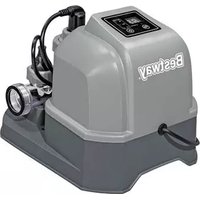
Flowclear 58400 - Water pump BESTWAY - Free user manual and instructions
Find the device manual for free Flowclear 58400 BESTWAY in PDF.
User questions about Flowclear 58400 BESTWAY
0 question about this device. Answer the ones you know or ask your own.
Ask a new question about this device
Download the instructions for your Water pump in PDF format for free! Find your manual Flowclear 58400 - BESTWAY and take your electronic device back in hand. On this page are published all the documents necessary for the use of your device. Flowclear 58400 by BESTWAY.
USER MANUAL Flowclear 58400 BESTWAY
text_image
DO NOT RETURN TO THE STORE QUESTIONS? PROBLEMS? MISSING PARTS? For FAQ, Manuals Or Spare Parts, Please Visit www.bestwaycorp.com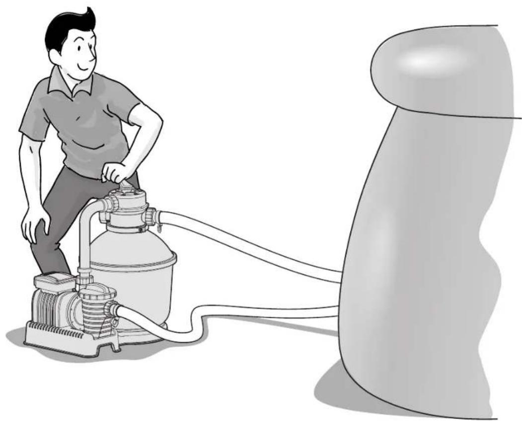
natural_image
Illustration of a man operating a large industrial pump connected to a cylindrical tank (no text or symbols present)FLOWCLEAR™ SAND FILTER OWNER'S MANUAL
www.bestwaycorp.com
Visit Bestway YouTube channel


SAFETY INSTRUCTIONS
WARNING
IMPORTANT SAFETY INSTRUCTIONS - READ AND FOLLOW ALL SAFETY INSTRUCTIONS - SAVE THESE INSTRUCTIONS
When installing and using this electrical equipment, basic safety precautions should always be followed, including the following:
- The pump is to be supplied by an isolating transformer or supplied through a residual current device (RCD) having a rated residual operating current not exceeding 30 mA.
- The power source on the wall of building should keep more than 4m away from pool and at a height of 1.2m at least.
- The appliance must be supplied by earthed power source.
- RISK OF ELECTRIC SHOCK - The pump cannot be using while people are inside the pool. Forbid the access of the pool in case of damage of the sand filter.
- DO NOT BURY CORD. Locate cord to minimize abuse from lawn mowers, hedge trimmers, and other equipment.
- To reduce the risk of electric shock, replace damaged cord immediately.
- If the supply cord is damaged, it must be replaced by the manufacturer, its service agent or similarly qualified persons in order to avoid a hazard.
- Extension cords can't be used.
- Risk of electric shock. Using the sand filter with an unmatched electrical supply is dangerous and will permanently damage the sand filter.
- Do not remove the grounding prong or modify the plug in anyway. Do not use adaptor plugs. Consult a qualified electrician for any questions relating to validity of your plugs or grounding.
- Handle the sand filter with care. Do not pull or carry the sand filter by the power cord. Never pull a plug from the outlet by yanking the power cord. Keep cord free from abrasions. Sharp objects, oil, moving parts, and heat should never be exposed to the sand filter.
• Always unplug this product from the electrical outlet before removing, cleaning, servicing or making any adjustment to the product.
- Don't plug or unplug the appliance if hand is wet
• Always unplug the appliance:
- On raining days
• Before cleaning or other maintenance - Leave it unattended on holidays
- When the appliance will be not used for long time, such as in the winter, the pool set should be disassembled and stored indoor.
- CAUTION: Read the instruction before using the appliance and installation/reassembly every time.
- Safekeeping the instruction. For reconstruction the pool set every time, please always refer to the instructions.
- If instruction is missed, please contact with Bestway or search it in website: www.bestwaycorp.com
• Electric installations should follow national wiring rules. Consult a qualified electrician for any questions.
CAUTION: This sand filter is for use with storable pools only. Do not use with permanently-installed pools. A storable pool is constructed so that it is capable of being readily disassembled for storage and reassembled to its original integrity. A permanently-installed pool is constructed in or on the ground or in a building such that it cannot be readily disassembled for storage.
- This appliance can be used by children aged from 8 years and above and persons with reduced physical, sensory or mental capabilities or lack of experience and knowledge if they have been given supervision or instruction concerning use of the appliance in a safe way and understand the hazards involved. Children shall not play with the appliance. Cleaning and user maintenance shall not be made by children without supervision.
- Cleaning and user maintenance must be performed by an adult above 18 years old who is familiar with the risk of electric shock.
NOTES:
- Place the sand filter on solid, level ground. Ensure the sand filter is at least 3.5 meters away from poolside. Keep distance as far as possible.
- Pay attention to position pool and sand filter so adequate ventilation, drainage, and access for maintenance is available. Never place the sand filter in an area that may accumulate water, or on a walking path with lots of foot traffic.
- It is necessary to have the plug accessible after installation of the pool. The plug of the sand filter shall be at least 3.5m away from the pool.
- Atmospheric conditions may affect the performance and life span of the sand filter; take adequate precautions to protect the sand filter from unnecessary wear and tear that may occur during periods of cold or hot weather and/or exposure to sun.
- Please examine and verify all sand filter components are present before use. Notify Bestway at the customer service address listed on this manual for any damaged or missing parts at the time of purchase.
- It is imperative to change as soon as possible all deteriorated parts. Only use parts approved by the manufacturer.
- Do not allow children or adults to lean or sit on the apparatus.
- Do not add chemicals to the sand filter.
- When chemical products are used to clean the pool water, it is recommended to respect a minimum filtration time to preserve the health of swimmers which depends on compliance of health regulation.
- Only the media provided or specified by the manufacturer is to be used with product installation.
- It is essential to check that the suction openings are not obstructed.
- It is advisable to stop the filtration during maintenance operations on the filtration system.
- Regularly monitor the filter clogging level.
- A weekly check is recommended for backwashing or cleaning. Minimum daily filtration operating time of 8 hours is recommended to ensure clear pool water.
- It is essential to change any damaged element or set of elements as soon as possible. Use only parts approved by person responsible for placing the product on the market.
- All filters and filter media shall be inspected regularly to ensure that there is not a build-up of detritus thus preventing good filtration. The disposal of any used filter media should also be in accordance with applicable regulations/legislation.
- Mind all the safety requirements and recommendations described in the manual. In case of doubt on the pump or any circulation devices, contact a qualified installer, or the manufacturer/importer/distributor. The water circulation installation shall comply with the European as well as national/local regulations, especially when dealing with electrical issues. Any change of valve position, pump size, grille size can cause a change of the flow and the suction velocity can be increased.
- This product is not intended for commercial use.

text_image
POOL ≥3.5mPlease read the instruction manual carefully and keep it for future reference. SAVE THESE INSTRUCTIONS
PUMP DISPOSAL

Meaning of crossed-out wheeled dustbin:
Do not dispose of electrical appliances as unsorted municipal waste, use separate collection facilities.
Contact your local government for information regarding the collection systems available.
If electrical appliances are disposed of in landfills or dumps, hazardous substances can leak into the groundwater and get into the food chain, damage your health and well-being.
When replacing old appliances with new ones, the retailer is legally obligated to take back your old appliance for disposals at least free of charge.
SPECIFICATIONS
| 655mm 348mm 568mm | Filter Diameter: | 348mm |
| Effective Fiter Area: | 0.095m²(1.02ft²) | |
| Max. Operating Pressure: | 0.84Bar(12PSI) | |
| Working sand filter pressure: | <0.45Bar(6.5PSI) | |
| Max. Water Temperature: | 35℃ | |
| Sand: | Not included | |
| Sand Size: | #20 silica sand,0.45-0.85mm | |
| Sand Capacity: | Approximately 18kg |
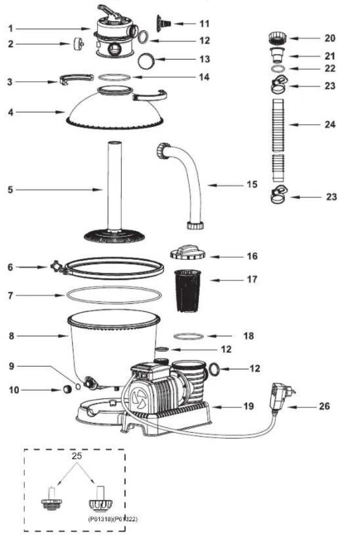
PARTS REFERENCE OVERVIEW
Before assembling the sand filter, take a few minutes to become familiar with all the sand filter parts.
text_image
Exploded diagram of a cleaning or cleaning device with numbered parts and labeled parts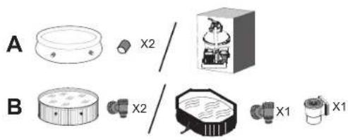
text_image
A B X2 X2 X1 X1| REF.NO | SPARE PART NO. | A | B |
| 1 | P61140 | 1 | 1 |
| 2 | P61138 | 1 | 1 |
| 3 | P6553 | 2 | 2 |
| 4 | P6620 | 1 | 1 |
| 5 | P6621 | 1 | 1 |
| 6 | P6622 | 1 | 1 |
| 7 | P6623 | 1 | 1 |
| 8 | P6905 | 1 | 1 |
| 9 | P6581 | 1 | 1 |
| 10 | P6580 | 1 | 1 |
| 11 | P6614 | 1 | 1 |
| 12 | P6029 | 5 | 5 |
| 13 | P6540 | 1 | 1 |
| 14 | P6149 | 1 | 1 |
| 15 | P6560 | 1 | 1 |
| 16 | P6561 | 1 | 1 |
| 17 | P6562 | 1 | 1 |
| 18 | P6563 | 1 | 1 |
| 19 | P6846 | 1 | 1 |
| 20 | P6615 | 5 | 3 |
| 21 | P6618 | 4 | 2 |
| 22 | P6005 | 4 | 2 |
| 23 | P6124 | 6 | 4 |
| 24 | P6042 | 2 | 2 |
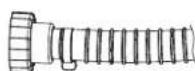
| 25 | P61322 | 1 | 0 |
| P61318 | 1 | 0 | |
| 26 | P6643 | 1 | 1 |
Assembly (You will need a screwdriver.)

-
Carefully remove all components from the package and check to ensure nothing is damaged. If equipment is damaged, immediately notify the retailer from where the equipment was purchased.
-
The sand filter should be placed on solid, level ground, preferably a concrete slab. Position the sand filter so the Ports and Control Valve are accessible for operation, servicing and winterizing.
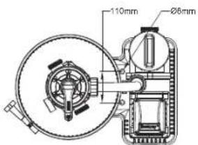
-
EN60335-2-41 TEST standard requires the sand filter to be vertically fixed on ground or a certain pedestal made of wood or concrete before use to prevent the sand filter from accideutally falling. Fully assembled sand filter will exceed 18kg. The mounting holes should be 8mm in diameter and spaced 110mm apart. Use two bolts and nuts with a maximum of 8mm in diameter to fasten the sand filter to the pedestal.
text_image
110mm Ø6mmLoad pool-grade filter sand.
NOTE: Use only special pool-grade filter sand, free of all limestone or clay: #20 Silica sand 0.45-0.85mm, approximately one 18kg bag should suffice. If you do not use the recommended size filter sand, filtering performance will be reduced and the sand filter may damaged, thereby voiding warranty.
NOTE: To avoid damaging the Skimmer when adding sand, pour some water into the Bottom Tank to submerse the Skimmer on the Collector Hub.
NOTE: SAND NOT INCLUDED.

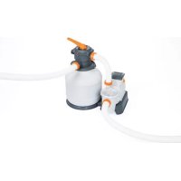
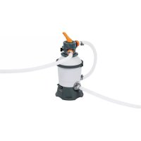
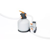
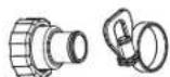
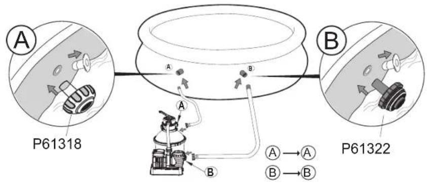
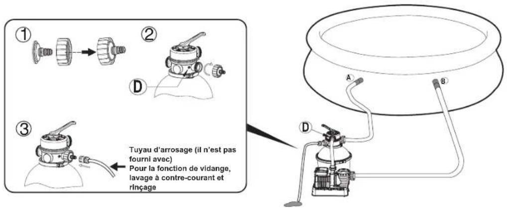
Connect to the pool
For 38mm(1.5in) connection


1
text_image
A P61318 B A B P61322 A→A B→B2
text_image
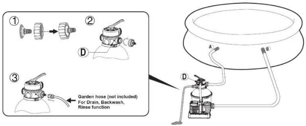
① ② D ③ Garden hose (not included) For Drain, Backwash, Rinse function A B D3

text_image
Diagram illustrating a mechanical device setup with labeled components A and B, showing hand positioning and cable connection.
STOP
Before switching on, please read the manual carefully.
OPERATION
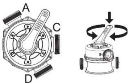
CONTROL VALVE OVERVIEW
WARNING: To prevent equipment damage and possible injury, always switch off sand filter before changing the Control Valve function. Changing valve positions while the pump is running can damage the Control Valve, which may cause personal injury or property damage.
How to Use the Control Valve:
Press down on the Control Valve handle and rotate to desired function.
text_image
A C D
S-S-005005
NOTE:
- Be sure all provisions for wastewater disposal meet applicable local, state or national codes. Do not discharge water where it will cause flooding or damage.
- When the Control Valve is set to the Backwash, Rinse, or Drain position, water will discharge from Port D on the Control Valve.
- Do not switch on or operate the sand filter with the Control Valve set to the Closed function or it will seriously damage the sand filter.
- Do not set the Control Valve between two functions, or it will lead to leaking.
• To avoid water leakage, screw the Port D Cap onto the Control Valve Port D before operating the filter or circulate function.
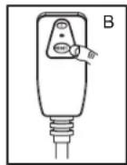
RCD Test
A. Insert the plug into the power outlet.
B. Press the "RESET" button; the indicator light turns red.
NOTE: If the indicator light is not on, the test has failed.
C. Press the "T" button; the indicator light turns off.
NOTE: If the indicator light is not off, the test has failed.
D. Press the "RESET" button, the indicator light turns red, and the sand filter is ready for use.
WARNING: RISK OF ELECTRIC SHOCK. The RCD plug must be tested before each use.
WARNING: Do not use the sand filter if this test fails. Please contact your local Bestway Aftersales Service.
WARNING: Insert the RCD plug into a residual current device (RCD) having a rated residual operating current not exceeding 30mA.


Air Release
Press down the control valve handle and wait until the water flow from Port D to release the air.
NOTE: It is important to repeat this operation every time you start the pump after winterizing, maintenance and backwashing the sand bed.
FIRST TIME USE INSTRUCTIONS
Backwash and Rinsing must be performed to prepare the pump for its first use and to wash the sand.
CAUTION: DO NOT DRY RUN THE SAND FILTER
- Press down on the Control Valve handle and rotate to the Backwash function.
- Plug in and run the sand filter for 3-5 minutes, or until the water runs clear.
- Switch off the sand filter and set the Control Valve to the Rinse function.
- Switch on the sand filter and run the sand filter for 1 min. This circulates water backwards through the sand filter and drains water out Port D.
- Switch off the sand filter. Set the Control Valve to the Closed function.
- Top up pool water if required.
IMPORTANT: This procedure removes water from the pool, which you'll need to replace.
Switch off the sand filter immediately if water levels near the pool's Inlet and Outlet valves.

- Now the sand filter is ready for use. Set the Control Valve to the Filter function.
NOTE: To prevent the risk of electrical shock dry any excess water from yourself and the sand filter.
- Switch on the sand filter to run it.
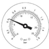
NOTE: The sand filter has now started its filtering cycle. Check that water is returning to the pool and take note of the filter pressure on Pressure Gauge. Generally, the recommended sand filter pressure is less than 0.45 Bar (6.5 PSI) when it is running.
Sand Filter Maintenance
CAUTION: You must ensure the sand filter is switched off and unplugged before any maintenance begins or severe risk of injury or death exists.
As dirt builds up in the sand filter, the pressure reading on Pressure Gauge will increase. When the Pressure Gauge is 0.45 Bar (6.5 PSI) or higher, or water flow to the pool is too low, it is time to clean the sand.
To clean the sand bed, follow all instructions outlined previously in :
Backwash and Rinsing.
NOTE:
- The Pressure Gauge is just used for measuring the water pressure, not used for precision measurement.
- We recommend you clean the sand bed once a month or less regularly depending on how often the pool is used. Do not clean the sand too frequently.

text_image
0.8 1 0.4 5 10 15 20 25 30 35 40 45 50 55 60 65 70 75 80 85 90 95 100 105 110 115 120 125 130 135 140 145 150 155 160 165 170 175 180 185 190 195 200 205 210 215 220 225 230 235 240 245 250 255 260 265 270 275 280 285 290 295 300 305 310 315 320 325 330 335 340 345 350 355 360 365 370 375 380 385 390 395 400 405 410 415 420 425 430 435 440 445 450 455 460 465 470 475 480 485 490 495 500Cleaning the Strainer
- Switch off the sand filter and set the Control Valve to the Closed function.
- Replace the Debris Screens with Stopper Plugs to prevent water from escaping.
- Remove the Strainer Cover by unscrewing it.
- Take out the Strainer, remove any debris.
- Put the Strainer back into position. Ensure the hole in the strainer is aligned.
- Ensure the Seal Ring is in place. Secure the Strainer Cover back.
- Remove the Stopper Plugs and insert the Debris Screens.
NOTE: The Strainer must be emptied and cleaned periodically. A dirty or blocked strainer will reduce the performance of the sand filter.

text_image
Diagram illustrating a recycling or waste sorting process with labeled components and directional arrowsLowering or Draining Pool Water
- Switch off the sand filter and set Control Valve to the Drain function.
- Detach the Hose from the pool's Port A and sand filter Port A and attach to Port D.
NOTE: Remember to replace the Debris Screen with Stopper Plug to prevent water from escaping. - Switch on the sand filter and press the "RESET" button to run the filter and remove the pool water.
WARNING: DO NOT DRY RUN THE SAND FILTER.
Winterizing
In areas that have freezing winter temperatures, pool equipment must be winterized to protect against damage. Allowing water to freeze will damage the sand filter and void warranty.
- Backwash the sand filter.
- Drain the pool according to the pool owner's manual.
- Unscrew the drain valve cap at the bottom of the tank and release the remaining water.
- Disconnect the two Hoses from the pool and the sand filter.
- Completely pour the sand out of the tank and dry all components.
- Store the sand filter in a dry location out of child's reach.
TROUBLESHOOTING
| Problems Probable Causes Solutions | ||
| Sand is flowing to the pool | - Sand is too small- Move the control valve from the backwash to the filter function without stop the sand filter- The level of the sand is too high- The skimmer is broken | - Recommend 0.45mm to 0.85mm #20 silica sand- Stop the sand filter every time set the control valve- Check if the level of the sand is between the marked “MAX” and “MIN” on the collector hub- Replace the skimmer |
| No water flow | - Stopper plugs were not removed- Air was not released- The control valve is set to Closed- The strainer is blocked- Sand filter broken | - Remove the stopper plugs and insert the debris screens- Release the air- Set to filter function- Clean the strainer- Call for service |
| Excessive filter pressure | - Dirty filter- Calcified sand bed- Insufficient backwashing- The pressure gauge is broken | - Backwash- Inspect sand and change if necessary- Backwash until water runs clear- Replace the pressure gauge |
| Control Valve leaks from the port D | - Control Valve is set between two functions- The gasket is broken | - Set to one function- Replace the gasket |
| Connectors leak | - Washer of the connectors not in place- Washer of the connectors broken- O-ring on the hose connection is broken- Loose Hoses | - Reposition the washer- Replace the washer- Replace the o-ring- Tighten them |
Limited BESTWAY® Manufacturer's Warranty
The product you have purchased comes with a limited warranty. Bestway® stands behind our quality guarantee and assures, through a replacement warranty, your product will be free from manufacturer's defects.
The following provision is only valid within the European member states countries: The legal regulation of Directive 1999/44/EC will not be effected by this BESTWAY limited warranty.
To enact a warranty claim, this form must be completed and submitted with a copy of your purchase receipt to your local Bestway After Sales Center. Please contact your local Bestway After Sales Center before sending any documents. They will provide full instructions of what is needed for your claim. Bestway ^23 will not replace any products deemed to have been damaged due to negligence or used outside of the owner's manual guidelines.
Bestway's warranty covers manufacturing defects discovered while unpacking the product or during use as recommended within the user manual. This warranty applies only to products which have not been modified by any 3rd parties. The product must be stored and handled in accordance with the technical recommendations.
The warranty does not cover damages caused by misuse, abuse, neglect, including, but not limited to collision, fire, use of incorrect voltage, excessive heat exposure, improper installation, improper wiring or testing, or improper storage.
Replacements and repairs don't extend the duration of the warranty. The Limited Warranty is valid for the period indicated above. The warranty start date is the date of sale shown on the original receipt/purchase invoice.
Please copy the Batch Number found on the body of the sand filter.

text_image
Batch Number
text_image
Batch Number
text_image
Batch Number
text_image
Batch NumberBatch Number: Date of purchase:
TO: BESTWAY® SERVICE DEPARTMENT Date: Customer Code Number:
FAX/E-MAIL/TEL: Please refer to your country according to the information found on the back cover or on our website: www.bestwaycorp.com
Please provide your address details in full. Note: Incomplete address details will result in delayed shipments.
Bestway reserves the right to charge for redelivery of undelivered packages where the recipient is at fault.
REQUIRED INFORMATION - PLEASE WRITE THE SHIPPING ADDRESS
Name: ____
Address: Zip code:
Country:
City: Mobile:
Telephone: ____
Fax: E-mail:
RetailerPlease Clearly Write Your Item Code:

text_image
Item Code HOLCICAR™ SAND FILTER MODEL #XXXXXXAll drawings for illustration purpose only. Not to scale.
Problem description
○ Water leakage
○ Stopped working
Missing part - Please use the code for the missing part. This can be found in the owner's manual.
○ Other (Please describe)_
IMPORTANT: ONLY THE DAMAGED PART WILL BE REPLACED, NOT THE COMPLETE SET.
Bestway reserves the right to request photographic evidence of defective parts, or to require sending the item for additional testing. In order to better assist you, we request all information you provide is complete.
FOR FAQ, MANUALS, VIDEOS OR SPARE PARTS, PLEASE VISIT OUR WEBSITE: www.bestwaycorp.com
VIDEOS ARE ALSO AVAILABLE ON OUR BESTWAY CHANNEL ON YOU TUBE: www.youtube.com/user/BestwayService

Bestway®
#58400
Hmax 1.5m

natural_image
Illustration of a man operating a water pump connected to a large cylindrical device, with no visible text or symbols on the diagram itself.SANDFILTER
FLOWCLEAR™
GEBRAUCHSANLEITUNG
www.bestwaycorp.com
text_image
POOL ×3.5mSPEZIFIKATIONEN
text_image
Exploded diagram of a cleaning or cleaning device with numbered parts and labeled parts
text_image
A B X2 X2 X1 X1| REF.-NR. | ERSATZTEIL NR. | A | B |
| 1 P61 | 140 1 1 | ||
| 2 P61 | 138 1 1 | ||
| 3 P65 | 53 2 2 | ||
| 4 P66 | 20 1 1 | ||
| 5 P66 | 21 1 1 | ||
| 6 P66 | 22 1 1 | ||
| 7 P66 | 23 1 1 | ||
| 8 P69 | 05 1 1 | ||
| 9 P65 | 81 1 1 | ||
| 10 P6 | 580 1 1 | ||
| 11 P6 | 14 1 1 | ||
| 12 P6 | 29 5 5 | ||
| 13 P6 | 40 1 1 | ||
| 14 P6 | 149 1 1 | ||
| 15 P6 | 60 1 1 | ||
| 16 P6 | 61 1 1 | ||
| 17 P6 | 62 1 1 | ||
| 18 P6 | 63 1 1 | ||
| 19 P6 | 46 1 1 | ||
| 20 P6 | 15 5 3 | ||
| 21 P6 | 18 4 2 | ||
| 22 P6 | 05 4 2 | ||
| 23 P6 | 124 6 4 | ||
| 24 P6 | 42 2 2 | ||
| 25 | P61322 1 0 | ||
| P61318 1 0 | |||
| 26 P6 | 43 1 1 |
text_image
110mm Ø6mmtext_image
Diagram illustrating a medical procedure involving a surgical instrument and a device with labeled parts A and B.text_image
Diagram illustrating a recycling or waste sorting process with labeled components and directional arrowsnatural_image
Illustration of a man operating a water pump connected to a large cylindrical device, with 'LOWCLEAR™' text below (no technical symbols or labels on the diagram itself)FLOWCLEAR™
ZANDFILTER
text_image
ZWEMiSAD >3.5mSPECIFICATIES
text_image
Exploded diagram of a cleaning or cleaning device with numbered parts and labeled parts
text_image
A X2 B X2 X1 X1| REF.NR. | NR. WISSELOND. | A | B |
| 1 P61 | 140 1 1 | ||
| 2 P61 | 138 1 1 | ||
| 3 P65 | 53 2 2 | ||
| 4 P66 | 20 1 1 | ||
| 5 P66 | 21 1 1 | ||
| 6 P66 | 22 1 1 | ||
| 7 P66 | 23 1 1 | ||
| 8 P69 | 05 1 1 | ||
| 9 P65 | 81 1 1 | ||
| 10 P6 | 580 1 1 | ||
| 11 P6 | 14 1 1 | ||
| 12 P6 | 29 5 5 | ||
| 13 P6 | 40 1 1 | ||
| 14 P6 | 149 1 1 | ||
| 15 P6 | 560 1 1 | ||
| 16 P6 | 561 1 1 | ||
| 17 P6 | 562 1 1 | ||
| 18 P6 | 563 1 1 | ||
| 19 P6 | 46 1 1 | ||
| 20 P6 | 15 5 3 | ||
| 21 P6 | 18 4 2 | ||
| 22 P6 | 005 4 2 | ||
| 23 P6 | 124 6 4 | ||
| 24 P6 | 42 2 2 | ||
| 25 | P61322 1 0 | ||
| P61318 1 0 | |||
| 26 P6 | 43 1 1 |
text_image
110mm Ø6mmtext_image
Diagram illustrating a medical procedure for using a pressure monitor to interact with a patient's neck, showing steps A and B with magnified views.
STOP
text_image
Diagram illustrating a recycling or waste sorting process with labeled components and directional arrowsWAARSCHUWING: LAAT DE ZANDFILTER NIET DROOG WERKEN
text_image
PISCINA >3.5mSPÉCIFICATIONS
text_image
Exploded diagram of a cleaning or cleaning device with numbered parts and labeled parts
text_image
A B X2 X2 X1 X1| RÉF.N° | PIÈCE DE RECHANGE N°. | A | B |
| 1 P61 | 140 1 1 | ||
| 2 P61 | 138 1 1 | ||
| 3 P65 | 53 2 2 | ||
| 4 P66 | 20 1 1 | ||
| 5 P66 | 21 1 1 | ||
| 6 P66 | 22 1 1 | ||
| 7 P66 | 23 1 1 | ||
| 8 P69 | 05 1 1 | ||
| 9 P65 | 81 1 1 | ||
| 10 P65 | 80 1 1 | ||
| 11 P66 | 14 1 1 | ||
| 12 P60 | 29 5 5 | ||
| 13 P65 | 40 1 1 | ||
| 14 P61 | 149 1 1 | ||
| 15 P65 | 60 1 1 | ||
| 16 P65 | 61 1 1 | ||
| 17 P65 | 62 1 1 | ||
| 18 P65 | 63 1 1 | ||
| 19 P68 | 46 1 1 | ||
| 20 P66 | 15 5 3 | ||
| 21 P66 | 18 4 2 | ||
| 22 P60 | 05 4 2 | ||
| 23 P61 | 124 6 4 | ||
| 24 P60 | 42 2 2 | ||
| 25 | P61322 1 0 | ||
| P61318 1 0 | |||
| 26 P66 | 43 1 1 |
text_image
Diagram showing progressive assembly of mechanical parts with arrows indicating progression1

text_image
A P61318 B A B P61322 A→A B→B2
text_image
Diagram illustrating a mechanical setup with labeled components A and B, showing hand fastening and gas flow paths.