
607 - Multimeter APPA - Free user manual and instructions
Find the device manual for free 607 APPA in PDF.

| Product Type | Digital multimeter with insulation tester |
| Brand | APPA |
| Model | 607 |
| Category | Multimeter |
| Power Supply | 4 alkaline batteries 1.5 V type LR6 or AA |
| Display | LCD 10000 count |
| Dimensions (L x W x H) | 95 mm x 52 mm x 207 mm (with holster) |
| AC/DC Voltage Measurements | Ranges mV, V up to 1000 V, accuracy 0.08% (DC) and 0.9% (AC) |
| AC/DC Current Measurements | Range mA up to 400.0 mA, accuracy 0.2% (DC) and 1.5% (AC) |
| Resistance Measurement | Up to 40.00 MΩ, accuracy 0.5% |
| Capacitance Measurement | Up to 40.00 mF, accuracy 1.2% |
| Temperature Measurement | From -200 to 1200 °C (K-type probe included), accuracy 1% + 1 °C |
| Frequency Measurement | Up to 100 kHz, accuracy 0.1% |
| Insulation Test | Voltages 50 V / 100 V / 250 V / 500 V / 1000 V, resistance up to 22 GΩ |
| Diode and Continuity Test | Diode up to 2.0 V, continuity with threshold 30 Ω |
| Special Functions | Hold, MIN/MAX/AVG, relative mode, data save and recall, HFR, auto/manual range selection |
| Safety and Standards | EN61010-1, CAT IV 600 V, CAT III 600 V, double insulation, overvoltage protection, voltage alert ≥ 30 V |
| Maintenance | Clean with a cloth and neutral detergent; do not use abrasives or solvents |
| Replacement Parts | Fuse 440 mA / 1000 V; alkaline batteries 1.5 V LR6 or AA |
| Environmental Conditions | Operating temperature: 0 °C to 50 °C (depending on humidity); storage: -20 °C to 60 °C; max altitude: 2000 m |
| Included Accessories | Installed batteries, test leads, user manual |
Frequently Asked Questions - 607 APPA
User questions about 607 APPA
0 question about this device. Answer the ones you know or ask your own.
Ask a new question about this device
Download the instructions for your Multimeter in PDF format for free! Find your manual 607 - APPA and take your electronic device back in hand. On this page are published all the documents necessary for the use of your device. 607 by APPA.
USER MANUAL 607 APPA
other
| Process | Value | | ------------- | --------- | | Press | 9.865 | | Increase Range | 9.87 |First Range
⚠️ Opgelet
CMRR / NMRR : (Common Mode Rejection Ratio) (Normal Mode Rejection Ratio)
(met teststroom = 1 mA) : 50V/50KΩ, 100V/100KΩ,
250V/250KΩ, 500V/500KΩ, 1000V/1 MΩ
Nauwkeurigheid testspanning : +20%, 0%
Kortsluitteststroom : 1mA
other
| Process | Value | | ------------- | --------- | | Press | 9.865 | | Increase Range | 9.87 |First Range
Attention!
Poids : (630g) piles incluses
50V/50KΩ, 1 00V/1 00KΩ, 250V/250KΩ, 500V/500KΩ, 1000V/1 MΩ
⚠ Safety Information
Understand and follow operating instructions carefully. Use the meter only as specified in this manual; otherwise, the protection provided by the meter may be impaired.
⚠ WARNING
Identifies hazardous conditions and actions that could cause BODILY HARM or DEATH
CAUTION
Identifies conditions and actions that could DAMAGE the meter or equipment under test
⚠ WARNING
- When using test leads or probes, keep your fingers behind the finger guards.
- Remove test lead from Meter before opening the battery door or Meter case.
- Use the Meter only as specified in this manual or the protection by the Meter might be impaired.
- Always use proper terminals, switch position, and range for measurements.
- Verify the Meter's operation by measuring a known voltage. If in doubt, have the Meter serviced.
- Do not apply more than the rated voltage, as marked on Meter, between terminals or between any terminal and earth ground.
- Only replace the blown fuse with the proper rating as specified in this manual.
- Use caution with voltages above 30 Vac rms, 42 Vac peak, or 60 Vdc. These voltages pose a shock hazard.
- To avoid false readings that can lead to electric shock and injury, replace battery as soon as low battery indicator.
- Disconnect circuit power and discharge all high-voltage capacitors before testing resistance, continuity, diodes, or capacitance.
- Do not use Meter around explosive gas or vapor.
- To reduce the risk of fire or electric shock do not expose this product to rain or moisture.
CAUTION
- Disconnect the test leads from the test points before changing the position of the function rotary switch.
- Never connect a source of voltage with the function rotary switch in , +, ^ , mA, INSULATION position.
- Do not expose Meter to extremes in temperature or high humidity.
- Never set the meter in _1 + t, ^ , mA, INSULATION function to measure the voltage of a power supply circuit in equipment that could result in damage the meter and the equipment under test.
Symbols as marked on the Meter and Instruction manual
| ⚠️ | Risk of electric shock |
| ⚠️ | See instruction manual |
| ≡≡ | DC measurement |
| ☐ | Equipment protected by double or reinforced insulation |
| ≡≡ | Battery |
| ≡≡ | Fuse |
| ⊥ | Earth |
| ~ | AC measurement |
| CE | Conforms to EU directives |
| ☒ | Do not discard this product or throw away. |
Unsafe Voltage
To alert you to the presence of a potentially hazardous voltage, when the Tester detects a voltage ≥ 30 V or a voltage overload (OL) in V, mV, insulation function. The "A" symbol is displayed and High voltage indicator is turned on.
Maintenance
Do not attempt to repair this Meter. It contains no userserviceable parts. Repair or servicing should only be performed by qualified personnel.
Cleaning
Periodically wipe the case with a dry cloth and detergent. Do not use abrasives or solvents.
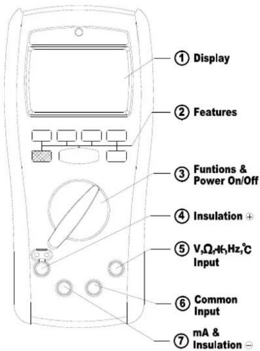
The Meter Description
Front Panel Illustration
- LCD display : 10000 counts
- Push-buttons for features.
- Rotary switch for turn the Power On / Off and select the function.
- Input Terminal for Insulation function.
- Input Terminal for V,Ω, +, Hz, °C functions.
- Common (Ground reference) Input Terminal for all functions expect Insulation function.
- Input Terminal for mA or Common Input Terminal for Insulation function.
Making Basic Measurements
Preparation and Caution Before Measurement ⚠️ : Observe the rules of ⚠ Warnings and ⚠ Cautions
When connecting the test leads to the DUT (Device Under Test) connect the common (mA) test lead before connecting the live lead; when removing the test leads removing the test live lead before removing the common test lead. The figures on the following pages show how to make basic measurements.
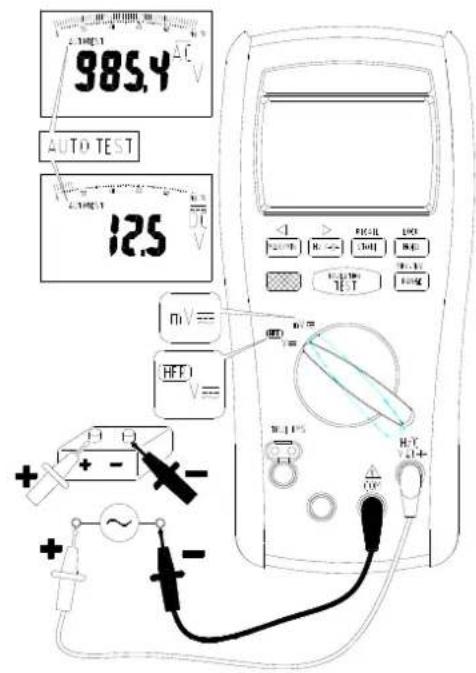
Measuring AC / DC Voltage
Measuring Resistance / Continuity / Diode
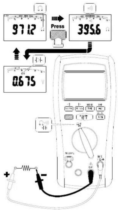
Press the Blue button to select the measuring function.
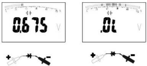
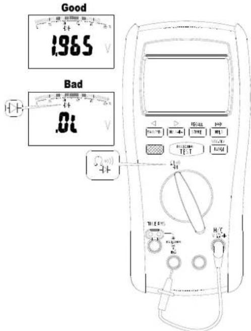
Testing Diode
Testing Continuity
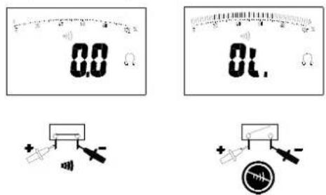
The buzzer allows you to quick continuity tests without having to watch the display. The buzzer sounds when a short (< 30Ω) is defected.
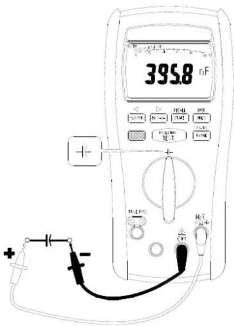
Measuring Capacitance
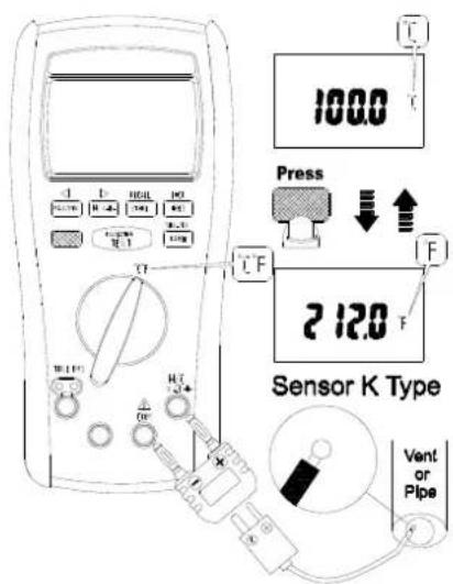
Measuring Temperature °C / °F
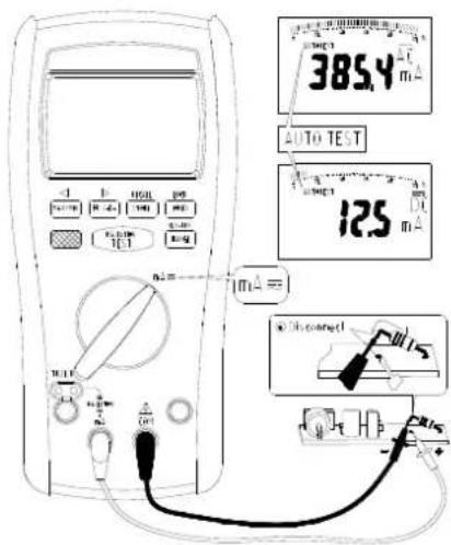
Measuring AC / DC Current
Measuring Insulation Resistance
Select test voltage
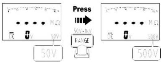
Press the Range button to select the test voltage (50V / 100V / 250V / 500V / 1000V)
Lock test voltage
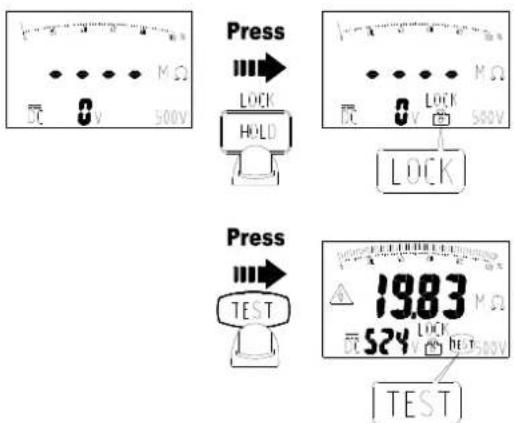
Press the Hold button to lock the test voltage. Press the button again to cancel the lock mode.
Make the reading stably
Press the Blue button to make the reading stably, the "Smooth" appears on the display. Press the Blue button again to cancel this mode.
Measuring Insulation Resistance
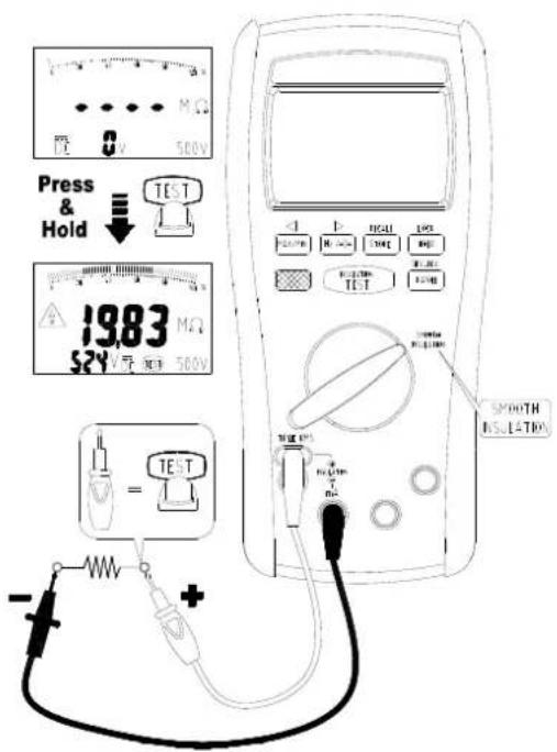
Insulation tests should only be performed on dead circuits. Check the fuse before testing. To measure insulation resistance, follow the steps below.
- Insert test probes in the “⊕” and “⊖” input terminals.
- Turn the rotary switch to Insulation position.
- Press the Range button to select the test voltage.
- Connect the probes to the circuit.
- Push and hold the Test button to start the test. The "Test" and "△" appear on the display. The secondary display shows the test voltage applied to the circuit under test. The primary display shows the resistance.
- Keep the probes on the test points and release the Test button. The resistance reading appears on the primary display until a new test is started or a different function or range is selected or > 30 V is detected.
Measuring Frequency for ACV, ACmV and ACmA
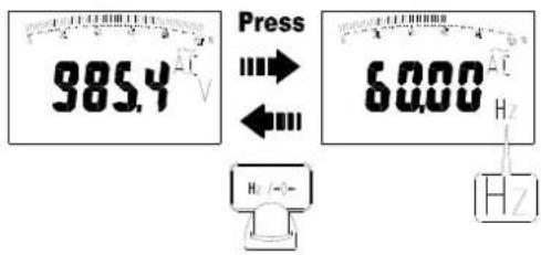
The meter measures the frequency of a voltage or current signal by counting the number of times the signal crosses a threshold level each second. To measure frequency, follow the steps below.
- Turn the rotary switch to V, mV or mA position.
- Press the Hz button to measure the frequency.
- Press the Hz button or change the rotary switch position to exit this function.
Display Hold
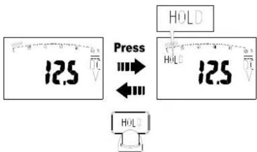
In the Hold mode, the meter holds the reading. To use the Hold mode, follow the steps below.
- Press the Hold button to activate Hold mode. The "Hold" appears on the display.
- Press the Hold button, Blue button, Range button or change the rotary switch position to exit this function.
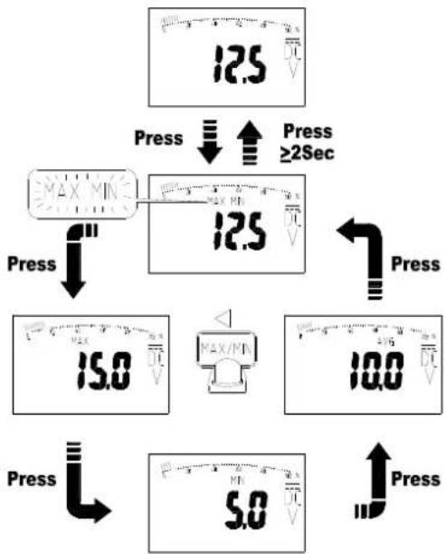
Display MAX / MIN / AVG
flowchart
graph TD
    A["12.5 V"] --> B["Press"]
    B --> C["12.5 V"]
    C --> D["Press"]
    D --> E["15.0 V"]
    E --> F["Press"]
    F --> G["5.0 V"]
    G --> H["Press"]
    H --> I["10.0 V"]
    I --> J["Press"]
    J --> K["≥2Sec"]
    style A fill:#f9f,stroke:#333
    style B fill:#ccf,stroke:#333
    style C fill:#cfc,stroke:#333
    style D fill:#fcc,stroke:#333
    style E fill:#cff,stroke:#333
    style F fill:#ffc,stroke:#333
    style G fill:#cfc,stroke:#333
    style H fill:#fcc,stroke:#333
    style I fill:#ffc,stroke:#333
    style J fill:#fcc,stroke:#333
    style K fill:#ffc,stroke:#333
The "MIN/MAX/AVG" mode records minimum and maximum input values. When the inputs go below the recorded minimum value or above the recorded maximum value, the meter beeps and records the new value. MIN/MAX/AVG mode can also calculate an average of maximum and minimum. To use the MIN/MAX/AVG mode, follow the steps below.
- Press the "MIN/MAX" button to activate MIN/MAX/AVG mode. The "MIN MAX" blinks on the display.
- Press the "MIN/MAX" button to step through the present readings, maximum, minimum and average (AVG).
- Press the "MIN/MAX" button for 2 seconds, Blue button, Range button or change the rotary switch position to exit this function.
Relative mode for / -
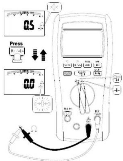
In the Relative mode, the meter records the present reading as reference and the later reading will subtract it. To use the Relative mode, follow the steps below.
- Turn the rotary switch to or position.
- Press the Hz button to activate Relative mode. The “→ 0 ←” blinks on the display.
- Press the Hz button, Blue button, Range button or change the rotary switch position to exit this function.
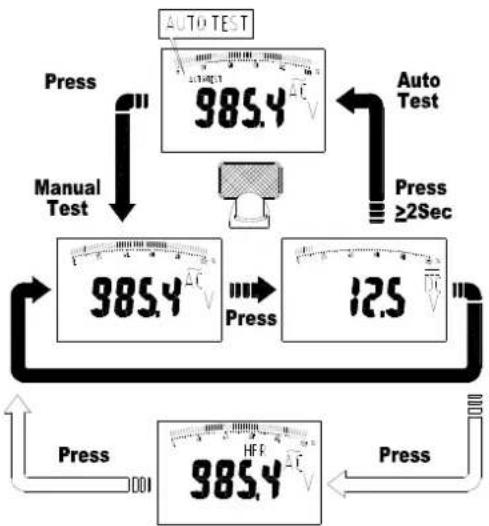
Auto Test and Manual Test
flowchart
graph TD
    A["985.4 V"] --> B["Manual Test"]
    B --> C["985.4 V"]
    C --> D["12.5 V"]
    D --> E["985.4 V"]
    E --> F["Auto Test"]
    F --> G["985.4 V"]
    G --> H["Press"]
    H --> I["Manual Test"]
    I --> J["985.4 V"]
    J --> K["12.5 V"]
    K --> L["Press"]
    L --> M["985.4 V"]
    M --> N["Press"]
    N --> O["Manual Test"]
    O --> P["985.4 V"]
    P --> Q["12.5 V"]
    Q --> R["Press"]
    R --> S["985.4 V"]
    S --> T["Press"]
    T --> U["Manual Test"]
    U --> V["985.4 V"]
    V --> W["12.5 V"]
    W --> X["Press"]
    X --> Y["985.4 V"]
The meter has both "AutoTest" mode and Manual Test mode.
- In the Auto Test mode, the meter compares the reading of AC and DC, and the bigger reading appears on the display. The meter beeps when the AC/DC mode has change.
- In the Manual Test mode, you override "AutoTest" and select the AC/DC mode yourself.
When you turn the rotary switch to V, mV or mA position, it defaults to Auto Test mode and the "AutoTest" appears on the display.
- To enter the Manual Test mode, press the Blue button.
- In the Manual Test mode, press the Blue button to change the AC/DC mode.
- Press the Blue button for 2 seconds to activate Auto Test mode.
High Frequency Reject mode
When the rotary switch in V position, the HFR mode can be used. To use HFR mode, press the Blue button in the Manual Test mode.
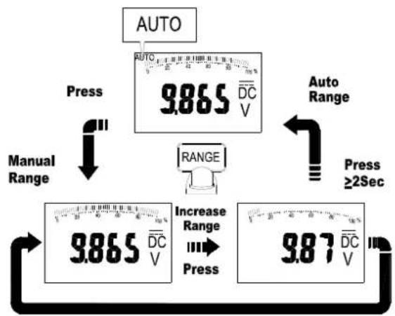
Auto Range and Manual Range
other
| Process | Value | | ------------- | --------- | | Press | 9.865 | | Increase Range | 9.87 |First Range
The meter has both Auto Range mode and Manual Range mode.
- In the Auto Range mode, the meter selects the range with the best resolution.
-
In the Manual Range mode, you select the range yourself. When you turn the meter on, it defaults to Auto Range mode and the "Range" appears on the display.
-
To enter the Manual Range mode, press the Range button. The "Range" disappears on the display.
- In the Manual Range mode, press the Range button to increment the range. After the highest range, the meter returns to the lowest range.
- Press the Range button for 2 seconds to activate Auto Range mode.
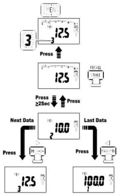
Store and Recall
flowchart
graph TD
    A["3"] --> B["Press"]
    B --> C["12.5 V"]
    C --> D["Press"]
    D --> E["12.5 V"]
    E --> F["FECALL STORE"]
    G["Next Data"] --> H["Press"]
    H --> I["12.5 V"]
    I --> J["10.0 V"]
    J --> K["Last Data"]
    K --> L["Press"]
    L --> M["100.0 V"]
    M --> N["Previous Display"]
You can store the reading on the display, and recall the reading on the display after.
• To store the reading press the Store button.
The data amount and "MEM" blink on the secondary display.
• Each function has a separate memory space. Each memory space has the maximum 100 amounts.
To recall the reading on the display, press the Store button for 2 seconds to activate Recall mode. The data amount shows on the secondary display. In the Recall mode, you can make the following operation.
- Press the ← button or → button to select the data amount.
- Press the ← button or → button for 2 seconds to search data quickly.
- Press the Blue button to clear all stored data in this function.
- Press the Store button for 2 seconds or change the rotary switch position to exit this function.
Auto Power Off
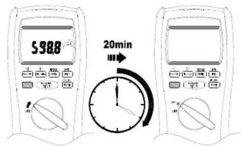
Wake-up the meter by switching rotor or pressing any button.
Auto Backlight
The backlight is automatically turned on at dark environment.
BUZZER
The meter beeps once for every valid key-press, and beeps twice for every invalid key-press.
Power On Options
Press button while turning the meter on from OFF position.
Blue button : Disable APO
MAX/MIN button : Disable auto backlight
Store button : Clear all stored data
Test button : Display LCD test frame
Range button : Default °C / °F reading
Battery and Fuse Replacement
Refer to the following figure to replace fuse and the batteries :
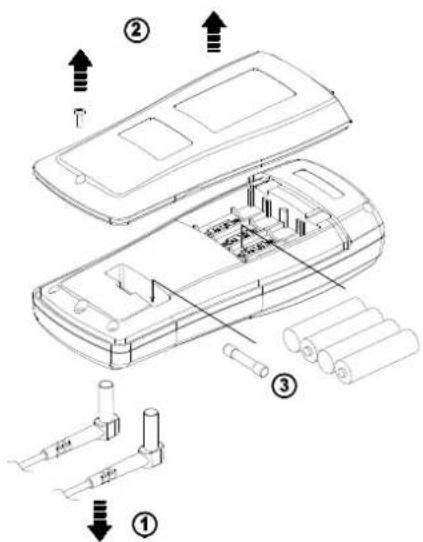
Caution
- Use only a fuse with the amperage, interrupt, voltage, and speed rating specified.
- Fuse rating: 440mA, 1000V fast blow fuse.
- Replace the batteries as soon as the low batteries indicator "☐" appears, to avoid false reading.
- 1.5V x 4 alkaline batteries.
Testing the fuse
Test the fuse as described below.
- Insert a test probe in the V, Ω, ⚙, Hz, °C input terminal.
- Turn the rotary switch to position, and press the Blue button to diode function.
- Insert the probe in the mA input terminal. If the display reading is 0L, the fuse is bad and should be replaced.
Specifications
General Specifications
Maximum voltage applied to any terminal :
1000 V ac rms or dc.
Display : 10000 counts.
Polarity Indication :
Automatic, positive implied, negative indicated.
Overrange Indication : OL
Batteries Life : ALKALINE 80 hours.
Insulation test : Tester can perform at least 600 insulation tests
with new alkaline batteries at room temperature.
These are standard tests of 1 MΩ at 1000 V with a duty cycle of
5 seconds on and 25 seconds off.
Low Batteries Indication : "☐" is displayed when the batteries
voltage drops below operating voltage.
Low battery voltage : Approx. 4.8V
Auto Power Off : Approx 20 minutes.
Operating Ambient: Non-condensing ≤10°C,
$$ 1 1 ^ {\circ} \mathrm{C} \sim 3 0 ^ {\circ} \mathrm{C} (\leq 80 \% \mathrm{RH}), $$
$$ 30^{\circ}\mathrm{C} \sim 40^{\circ}\mathrm{C} (\leq 75\% \mathrm{RH}), $$
$$ 40^{\circ}\mathrm{C} \sim 50^{\circ}\mathrm{C} (\leq 45\% \mathrm{RH}) $$
Storage Temperature :
-20°C to 60°C, 0 to 80% R.H. (batteries not fitted)
Safety : Complies with EN61010-1, UL61010-1, IEC 61010-1,
CAT.IV. 600V, CAT.III. 1000V
CAT
Application field
| I | The circuits not connected to mains. |
| II | The circuits directly connected to Low-voltage installation. |
| III | The building installation. |
| IV | The source of the Low-voltage installation. |
Compliance to EN 61557 : IEC61557-1, IEC61557-2,
IEC61557-4, IEC61557-10
Weight : (630g) including battery.
Dimensions (W x H x D) :
95mm x 207mm x 52mm with holster.
Accessories : Battery (installed), Test leads and user manual.
Power Requirements : 1.5V x 4 IEC LR6 or AA size.
Pollution degree : 2
EMC : EN 61326-1
Shock vibration : Sinusoidal vibration per MIL-T- 28800E (5 \~ 55 Hz, 3g maximum).
Drop Protection : 4 feet drop to hardwood on concrete floor. Indoor Use.
Electrical Specifications
Accuracy is ±(% reading + number of digits) at 23°C ± 5°C < 80%RH.
AC Voltage Measurement
| Function | Range | Accuracy | |
| 50Hz to 60Hz | 60Hz to 5kHz | ||
| ACmV | 100.00mV | ±(0.9%+3d) | ±(0.9%+3d) |
| 1000.0mV | ±(0.9%+3d) | ±(0.9%+3d) | |
| ACV | 10.000V | ±(0.9%+3d) | ±(1.9%+3d) |
| 100.00V | ±(0.9%+3d) | ±(1.9%+3d) | |
| 1000.0V | ±(0.9%+3d) | ±(1.9%+3d) [1] | |
| HFR ACV | 10.000V | ±(0.9%+3d) | ±(2.9%+3d) [2] |
| 100.00V | ±(0.9%+3d) | ±(2.9%+3d) [2] | |
| 1000.0V | ±(0.9%+3d) | ±(2.9%+3d) [2] | |
| [1] 60Hz to 1kHz[2] 60Hz to 500Hz | |||
DC voltage Measurement
| Function | Range | Accuracy |
| DCmV | 100.00mV | ±(0.08%+3d) |
| 1000.0mV | ±(0.08%+2d) | |
| DCV | 10.000V | ±(0.08%+2d) |
| 100.00V | ±(0.08%+2d) | |
| 1000.0V | ±(0.08%+2d) |
Over voltage protection : 1000V AC rms or DC.
The cut-off frequency of the high frequency reject : 1 kHz. Input Impedance : 10MΩ // less than 100pF.
CMRR / NMRR : (Common Mode Rejection Ratio)
(Normal Mode Rejection Ratio)
V_AC : CMRR > 60dB at DC, 50Hz / 60Hz
V_DC : CMRR > 100dB at DC, 50Hz / 60Hz
NMRR > 50dB at DC, 50Hz / 60Hz
AC conversions are ac-coupled, true rms responding, calibrated to the sine wave input.
For non-sine wave add the following Crest Factor corritions :
For Crest Factor of 1.4 to 2.0, add 1.0% to accuracy.
For Crest Factor of 2.0 to 2.5, add 2.5% to accuracy.
For Crest Factor of 2.5 to 3.0, add 4.0% to accuracy.
CF 3 @ 330V, 2 @ 500V
AC/DC Current Measurement
| Function Range Accuracy | ||
| DCmA | 100.00mA | ±(0.2%+2d) |
| 400.0mA | ±(0.2%+2d) | |
| ACmA | 100.00mA | ±(1.5%+2d) [1] |
| 400.0mA | ±(1.5%+2d) [1] | |
| [1] 50Hz to 5kHz | ||
Overload Protection :
mA Input : Max 440mA
AC Conversion Type : Conversion type and additional specification are same as DC/AC voltage.
Maximun Input Current Restriction Time : 10 minutes
Frequency Measurement for ACV/ACmV/ACmA
| Function Range Accuracy | ||
| Frequency | 100.00Hz | ±(0.1%+5d) |
| 1000.0Hz | ±(0.1%+5d) | |
| 10.000kHz | ±(0.1%+5d) | |
| 100.00kHz | ±(0.1%+5d) | |
Frequency Counter Sensitivity
| Function | Input Range (AC) | V_AC Sensitivity (RMS Sine Wave) | |
| 10Hz to 10kHz | 10kHz to 100kHz | ||
| ACmV | 100.00mV | 15.00mV | 15.00mV |
| 1000.0mV | 150.0mV 150.0mV | ||
| ACV | 10.000V | 1.500V 1.500V | |
| 100.00V | 3V | - | |
| 1000.0V | 30V | - | |
| ACmA | 100.00mA | 15.00mA | - |
| 400.0mA | 30mA | - | |
Minimun Pulse Width : >10us
Overload Protection : 1000V AC rms or DC
Resistance Measurement
| Function Range Accuracy | ||
| Resistance | 1000.0Ω | ±(0.5%+2d) |
| 10.000KΩ | ±(0.5%+2d) | |
| 100.00KΩ | ±(0.5%+2d) | |
| 1000.0KΩ | ±(0.5%+2d) | |
| 10.000MΩ | ±(0.5%+2d) | |
| 40.00MΩ | ±(0.5%+2d) | |
Open Circuit Voltage : Approximate -0.25V
Short Circuit Current : Approximate -0.25mA
Overload Protection : 1000V AC rms or DC
Continuity and Diode Measurement
| Function Range Accuracy | ||
| Continuity | 400.0Ω | ±(0.5%+2d) |
| Diode 2.000V ±(0.5%+2d) | ||
Continuity : Built-in buzzer sounds when measured resistance is less than 30Ω and sounds off when measured resistance is more than 100Ω, between 30Ω to 100Ω the buzzer maybe sound or off either.
Continuity MAX Test Current : -0.25mA
Continuity MAX Open Circuit Voltage : -1.2V
Diode MAX Test Current : 0.6mA
Diode MAX Open Circuit Voltage : 2.5V
Overload Protection : 1000V AC rms or DC
Capacitance Measurement
| Function | Range | Measuring Time | Accuracy |
| Capacitance | 10.000nF | 0.7sec ±(1.2%+80d) | |
| 100.00nF | 0.7sec ±(1.2%+20d) | ||
| 1000.0nF | 0.7sec | ±(1.2%+2d) | |
| 10.000uF | 0.7sec ±(1.2%+2d) | ||
| 100.00uF | 0.7sec ±(1.2%+2d) | ||
| 1000.0uF | 3.75sec ±(1.2%+2d) | ||
| 10.000mF | 7.5sec | ±(1.2%+20d) | |
| 40.00mF | 7.5sec | ±(1.2%+80d) |
Overload Protection : 1000V AC rms or DC
Temperature Measurement
| Function Range Accuracy | ||
| Temperature | -200.0 ~ 0.0 °C | ±(1%+2°C) |
| 0.0 ~ 1200 °C | ±(1%+1°C) | |
| -328.0 ~ 32.0 °F | ±(1%+36°F) | |
| 32.0 ~ 2192 °F | ±(1%+18°F) | |
Overload Protection : 1000V AC rms or DC
Insulation Resistance Measurement
| Test Voltage Range Accuracy | ||
| 50V | 2.000MΩ | ±(1.5%+5d) |
| 20.00MΩ | ±(1.5%+5d) | |
| 55.0MΩ | ±(1.5%+5d) | |
| 100V | 2.000MΩ | ±(1.5%+5d) |
| 20.00MΩ | ±(1.5%+5d) | |
| 110.0MΩ | ±(1.5%+5d) | |
| 250V | 2.000MΩ | ±(1.5%+5d) |
| 20.00MΩ | ±(1.5%+5d) | |
| 200.0MΩ | ±(1.5%+5d) | |
| 275MΩ | ±(1.5%+5d) | |
| 500V | 2.000MΩ | ±(1.5%+5d) |
| 20.00MΩ | ±(1.5%+5d) | |
| 200.0MΩ | ±(1.5%+5d) | |
| 550MΩ | ±(1.5%+5d) | |
| 1000V | 2.000MΩ | ±(1.5%+5d) |
| 20.00MΩ | ±(1.5%+5d) | |
| 200.0MΩ | ±(1.5%+5d) | |
| 2000MΩ | ±(1.5%+5d) | |
| 22.0GΩ | ±(10%+3d) | |
Test Voltage vs. Maximum Resistance Range :
50V/55.0MΩ, 100V/110.0MΩ, 250V/275MΩ, 500V/550MΩ, 1000V/22.0GΩ.
Test Voltage vs. Minimum Resistance Range (with Test Current = 1mA):
50V/50KΩ, 100V/100KΩ, 250V/250KΩ, 500V/500KΩ, 1000V/1MΩ.
Test Voltage Accuracy : +20%, -0%
Short Circuit Test Current : 1mA
Auto Discharge Function :
Discharge time < 1 sec for C ≤ 1μF
Maximum Capacitive Load : Operable with up to 1μF load
Live Circuit Detection : if ≥ 30V AC/DC at inputs, test inhibited
Overload Protection : 600V AC rms or DC
Limited Warranty
This meter is warranted to the original purchaser against defects in material and workmanship for 2 years from the date of purchase. During this warranty period, Manufacturer will, at its option, replace or repair the defective unit, subject to verification of the defect or malfunction.
This warranty does not cover Carlos fuses, disposable batteries, or damage from abuse, neglect, accident, unauthorized repair, alteration, contamination, or abnormal conditions of operation or handling.
Any implied warranties arising out of the sale of this product, including but not limited to implied warranties of merchantability and fitness for a particular purpose, are limited to the above.
The manufacturer shall not be liable for loss of use of the instrument or other incidental or consequential damages, expenses, or economic loss, or for any claim or claims for such damage, expense or economic loss. Some states or countries laws vary, so the above limitations or exclusions may not apply to you.
F-91423 MORANGIS CEDEX (France)
T: 01.60.11.42.12
F: 01.60.11.17.78
E-mail: info@turbotronic.fr