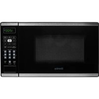
DOM014401G1 - Microwave Oven DANBY - Free user manual and instructions
Find the device manual for free DOM014401G1 DANBY in PDF.

| Product Type | Built-in Microwave Oven with Hood |
| Brand | Danby |
| Model | DOM014401G1 |
| Capacity | 38 L (1.4 cu. ft) |
| Turntable Diameter | 325 mm (12.8 in) |
| External Dimensions (W×D×H) | 60.6 × 44.5 × 42.4 cm (23.8 × 17.5 × 16.7 in) |
| Net Weight | 23.5 kg (51.8 lb) |
| Rated Voltage | 120 V ~ 60 Hz |
| Microwave Power | Not specified |
| Ventilation Types | Top, rear or recirculation exhaust |
| Included Accessories | Mounting plate, exhaust adapter, grease filters, templates |
| Charcoal Filter | Available for recirculation installation (replace every 6-12 months) |
| Safety | Door locks, grounding, liquid overheating protection |
| Maintenance | Regular cleaning of sealing surfaces and grease filters |
| Spare Parts | Available at DanbyApplianceParts.com or .ca |
Frequently Asked Questions - DOM014401G1 DANBY
User questions about DOM014401G1 DANBY
0 question about this device. Answer the ones you know or ask your own.
Ask a new question about this device
Download the instructions for your Microwave Oven in PDF format for free! Find your manual DOM014401G1 - DANBY and take your electronic device back in hand. On this page are published all the documents necessary for the use of your device. DOM014401G1 by DANBY.
USER MANUAL DOM014401G1 DANBY
Do the right thing\*
MODEL • MODÈLE • MODELO
DOM014401G1
24" OVER THE RANGE SENSOR MICROWAVE INSTALLATION MANUAL....1 - 22
MICRO-ONDES DE CUISSON À CAPTEUR DE 24" AU-DESSUS DE LA PLAGE MANUEL D'INSTALLATION....23 - 44
This equipment generates and uses ISM frequencies and if not installed and used properly in strict accordance with the manufacturer's instructions, it may cause interference to radio and television reception. It has been type-tested and found to comply with limits for ISM Equipment pursuant to Part 18 of FCC Rules, which are designed to provide reasonable protection against such interference in a residential installation.
However, there is no guarantee that interference will not occur in particular installations. If this equipment does cause interference to radio or television reception, which can be determined by turning the equipment off and on, the interference can be corrected by one or more of the following methods:
- Reorient the receiving antenna of radio or television.
- Move the microwave oven away from the receiver.
- Plug the microwave into a different outlet so that microwave and receiver are on different branch circuits.
The manufacturer is not responsible for any radio or TV interference caused by unauthorized modification of this appliance. It is the responsibility of the user to correct such interference.
AVOID POSSIBLE EXPOSURE TO EXCESSIVE MICROWAVE ENERGY
- Do not attempt to operate the appliance with the door open as this can result in harmful exposure to microwave energy. Do not tamper with or attempt to defeat the safety locks.
- Do not place any object between the front face and the door or allow soil or cleaner residue to accumulate on the sealing surfaces.
- Do not operate the appliance if it is damaged. The door must close properly and there must be no damage to the hinges, latches, door, door seals or sealing surfaces.
GROUNDING INSTRUCTIONS
This appliance must be grounded. In the event of an electrical short circuit, grounding reduces the risk of electrical shock by providing an escape wire for the electrical current.
This appliance is equipped with a cord that has a grounding wire with a grounding plug. The power cord must be plugged into an outlet that is properly grounded. If the outlet is a standard 2-prong wall outlet, it is your responsibility to have it replaced with a properly grounded 3-prong wall outlet. The serial rating plate indicates the voltage and frequency the appliance is designed for.
WARNING - Improper use of the grounding plug can result in a risk of electric shock. Consult a qualified electrician or service agent if the grounding instructions are not completely understood, or if doubt exists as to whether the appliance is properly grounded.
DO NOT USE AN EXTENSION CORD
Do not connect your appliance to extension cords or together with another appliance in the same wall outlet. Do not splice the power cord. Do not under any circumstances cut or remove the third ground prong from the power cord.
If the power supply cord is damaged, it must be replaced by the manufacturer, its service agent or similar qualified person in order to avoid hazard.
SAFETY INSTRUCTIONS
- Ensure that component parts are replaced with like components and that servicing is done by factory authorized service personnel, to minimize the risk of possible ignition due to incorrect parts or improper service.
- Check the appliance for damage before using. If there is any damage to the appliance, do not use it, return it to its point of purchase or contact consumer care.
- The appliance must be placed on a flat, stable surface that is able to hold its weight and the heaviest food likely to be placed in the appliance.
- Do not use this appliance where heat, moisture or high humidity are generated.
- Do not clean this appliance with or use near combustible materials.
• Children should be supervised to ensure that they do not play with the appliance. - This appliance is specifically designed to heat, cook or dry food. It is not designed for industrial or laboratory use.
- Do not store or use this appliance outdoors. Do not use this appliance near water.
- Do not overcook food. Carefully watch the appliance when it is in use.
- Remove wire twist-ties before placing items in the appliance.
- Do not use the appliance for storage purposes. Do not leave items inside the appliance when not in use.
- Do not heat oil or fat for deep frying as it is difficult to control the temperature of oil in a microwave.
- Some items such as whole eggs or sealed containers have the possibility of exploding when heated and should not be placed in this appliance.
- Do not operate any heating or cooking appliance beneath this appliance.
- Ensure that the glass tray and rollers are in the correct position before use to avoid possible spills.
- Do not operate this appliance when it is empty as this will increase the heat around the magnetron and can damage the appliance or cause a fire.
- If items inside the appliance should ignite, keep the door closed, turn the appliance off and disconnect the power cord.
- Do not operate the appliance without the glass tray, roller support and shaft in their correct positions.
SAFETY - SUPERHEATED LIQUID
Liquids are able to be overheated beyond the boiling point without appearing to be boiling due to the surface tension of the liquid. Visible bubbling will not always be present when the liquid is removed from the appliance. This could result in very hot liquids suddenly boiling over when a utensil or other item such as a tea bag is inserted into the liquid.
To reduce the risk of injury:
- Do not overheat liquids. Do not heat any liquid for more than 2 minutes per cup.
• Stir liquids before and halfway through heating. - Do not use straight-sided containers with narrow necks as this can cause a build up of steam.
- Superheated liquid can begin to spontaneously boil when removed from the microwave. After heating, allow the liquid to stand in the microwave for 30 seconds before removing.
- Use extreme care when inserting a utensil or other item into hot liquids.
- The contents of milk bottles and baby food jars should be stirred or shaken and the temperature checked before serving in order to avoid burns.
- Do not defrost frozen beverages, especially carbonated beverages, in this appliance as they could explode.
- Hot foods and steam can cause burns. Be careful when opening any container that has been heated in the appliance. Direct the opening away from hands and face to avoid burns.
SAFETY - ARCING
Arcing refers to sparks inside the microwave while it is in operation. Arcing is caused by:
• Metal or foil inside the appliance.
• Recycled paper towels being used inside the appliance, as these can contain small pieces of metal.
If arcing is present, stop operation and remove any metal or paper towels from the appliance.
| Oven capacity: | 38 L1.4 cu. ft. |
| Turntable diameter: | 325 mm 12.8 in |
| External dimensions: | 60.6 x 44.5 x 42.4 cm23.8 x 17.5 x 16.7 in |
| Net weight: | 23.5 kg51.8 lbs |
| Rated voltage: 120 V | ~ 60 Hz |
SAVE THESE INSTRUCTIONS!
INSTALLATION INSTRUCTIONS
- Remove all packing materials from the inside and outside of the appliance. Do not remove the cardboard mica sheet covering the magnetron.
- Check the appliance for damage before using, such as a misaligned or bent door, damaged door seals, broken or loose door hinges or latches, or dents inside the cavity or on the door. If there is any damage to the appliance, do not use it, return it to its point of purchase or contact consumer care.
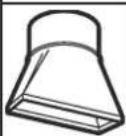
- The mounting surface must be capable of supporting the cabinet load in addition to the added weight of this microwave, approximately 22.6 - 31.7 kg (50 - 70 pounds), plus additional oven loads of up to 22.6 kg (50 pounds) for a total weight of 45.2 - 54.3 kg (100 - 120 pounds).
- This appliance cannot be installed in cabinet arrangements such as an island or peninsula. It must be mounted to both a top cabinet and a wall.
- Do not clean this appliance with or use near combustible materials.
- Do not block any ventilation openings on the appliance.
- Do not operate the appliance without the glass tray, roller support and shaft in their correct positions.
- Make sure the shelf is positioned properly inside the microwave to prevent damage from arcing. Do not use the microwave with the shelf on the floor of the microwave. Do not use the shelf when cooking popcorn. Always use pot holders when removing the shelf as it may be hot.
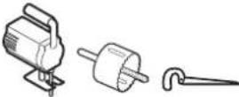
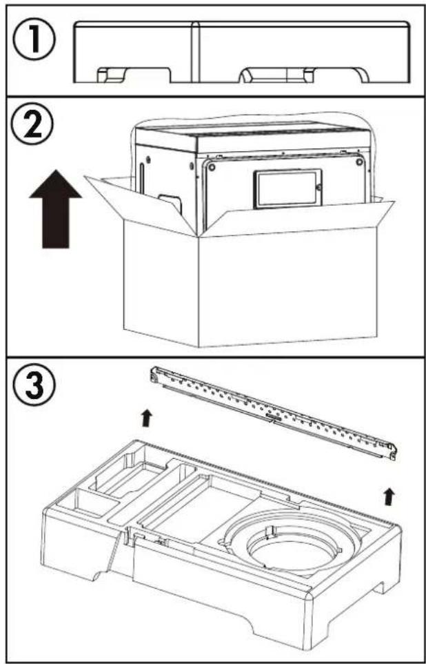
PARTS INCLUDED
| PART QTY | ||
| Mounting plate | 1 | |
| Exhaust adapter | 1 | |
| Top cabinet template | 1 | |
| Rear wall template | 1 | |
| Extra grease fl iters | 2 | |
INSTALLATION ACCESSORIES
| PART QTY | ||
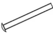
 | Wood screw (1/4'' × 2'') | 2 |
 | Wing nut 2 | |
 | Machine screw (3/16'' × 3'') | 2 |
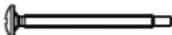 | Self aligning machine screw (1/4''-20 × 3'') | 2 |
 | Nylon grommet(for metal cabinets) | 1 |
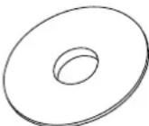 | Washer 2 | |
 | Sheet metal screw 2 | |
INSTALLATION INSTRUCTIONS
REQUIRED TOOLS
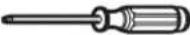 #1 and #2 Phillips screwdrivers #1 and #2 Phillips screwdrivers |  Pencil Pencil | 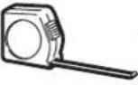 | [Ruler or tape measure straight edge] | 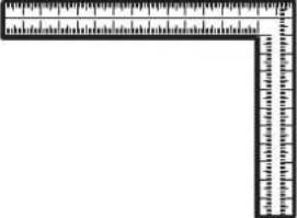 Carpenter square (optional) Carpenter square (optional) |
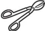 Tin snips (to cut damper, if needed) Tin snips (to cut damper, if needed) | 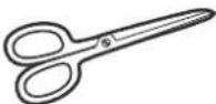 Scissors (to cut template, if needed) Scissors (to cut template, if needed) | 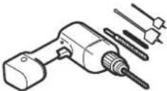 Electric drill with 3/16", 1/2" and 5/8" bits Electric drill with 3/16", 1/2" and 5/8" bits | 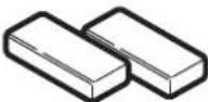 Filler blocks or scrap wood pieces (for top cabinet spacing in recessed bottom cabinet installations, if needed) Filler blocks or scrap wood pieces (for top cabinet spacing in recessed bottom cabinet installations, if needed) | |
 Gloves Gloves |  Safety goggles Safety goggles |  Duct and masking tape Duct and masking tape | ||
 Saw (saber, hole, or keyhole) Saw (saber, hole, or keyhole) | 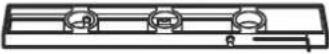 Level Level |  Edge-to-edge stud finder or hammer (optional) Edge-to-edge stud finder or hammer (optional) | 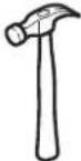 | |
LOCATION
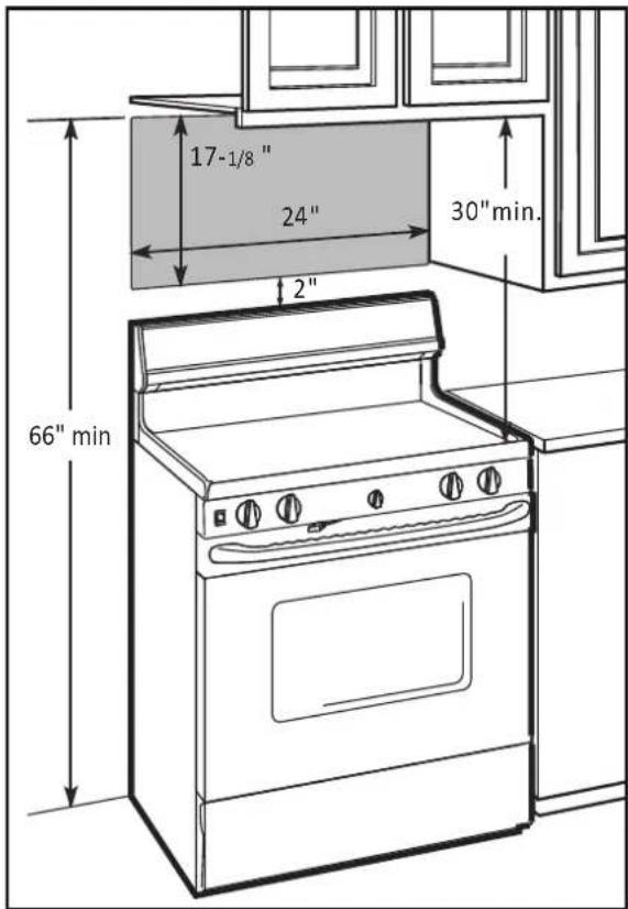
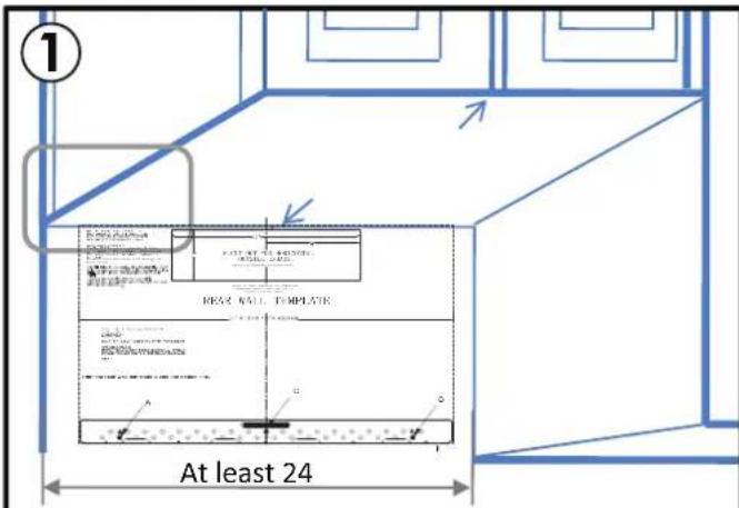
- The space between the cabinets must be 30" wide and free of obstructions.
- If the space between the cabinets is greater than 30", use thicker material to fill the gap between the microwave oven and the cabinets.
- This microwave is for installation over ranges up to 24" wide.
- If installing the microwave beneath smooth, fl at cabinets, be sure to follow the instructions for power cord clearance.
INSTALLATION INSTRUCTIONS
UNPACKING THE APPLIANCE
- Open the carton and remove the upper foam from the box. Keep the accessories.
- Remove the microwave from the carton and remove the plastic bag.
- Remove the mounting bracket from the upper foam.
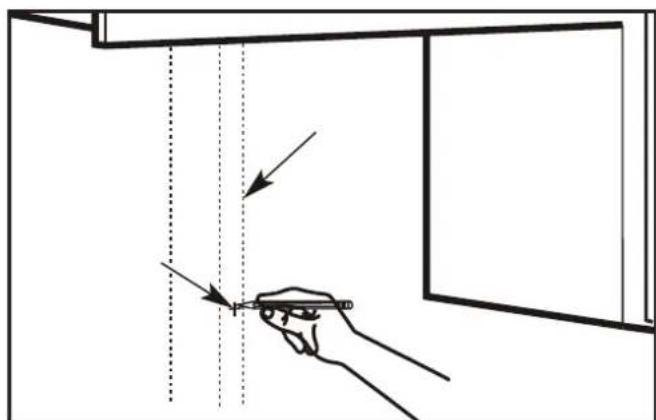
FINDING THE WALL STUDS
- Use a stud fi nder to locate the wall stud. If a stud fi nder is not available, use a hammer to tap lightly on the wall to find a solid sound. This sound indicates the location of the wall stud.
- Find the center of the wall stud by probing the wall with a small nail to find the edges of the stud. Draw a line down the center of the wall stud.
Note: The microwave must be connected to at least one wall stud.
INSTALLATION INSTRUCTIONS
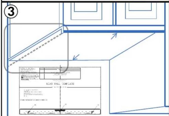
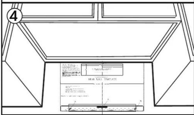
USING THE INSTALLATION TEMPLATE
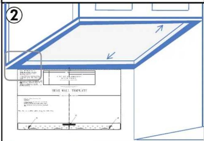
There are three different types of cabinetry that will change how the rear wall template should be used to determine where to install the mounting bracket.
- Flat bottomed cabinet: The top of the template should align with the bottom of the cabinet.
- Framed recessed cabinet: The top of the template should align with the back frame of the cabinet bottom.
- Framed recessed bottom cabinet with front overhang: The top of the template should align with the front overhang. It may be helpful to measure the overhang, then measure the same distance from the bottom of the cabinet and mark that spot.
- Aligning the center line of the rear wall template: Measure the space where the microwave will be installed and find the center line. Mark this line with a pencil and straight edge. Align the center line of the template with the center line on the wall.
INSTALLATION INSTRUCTIONS
TEMPLATE DAMAGED OR UNUSABLE
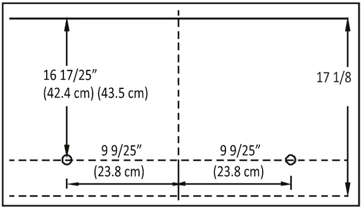
If the template arrives damaged or cannot be used, measure and mark the wall with these dimensions. Remember that the microwave must be level.
The bottom edge of the mounting plate must be 17 1/8" (43.5 cm) from the bottom edge of the upper cabinet.
The mounting plate holes must be 16 17/25" (42.4 cm) from the bottom edge of the upper cabinet and must be in line with each other. Each hole must be 9 9/25" (23.8 cm) from the center line.
Mark the template location on the wall but do not install the template yet. The exhaust duct work must be installed first.
other
| Dimension | Value | | :--- | :--- | | Top Section | 16 17/25" (42.4 cm) (43.5 cm) | | Middle Section | 9 9/25" (23.8 cm) | | Bottom Section | 9 9/25" (23.8 cm) | | Right Section | 17 1/8 | The chart displays a schematic layout with four vertical segments and two horizontal segments, each annotated with a numerical value and a circular symbol indicating the length of the segment.NOTES
Any decorative trim on the cabinetry or wall should be removed before installing the microwave.
Use a level to ensure that the template is level before marking the wall. The microwave must be level to ensure proper functioning.
At least three screws must be used to install the mounting plate. At least one of those screws must be in a wall stud.
Tape the mounting template to the wall and then mark the three screw holes at the bottom of the template. Remove the template and double check the marked holes with the actual mounting plate to ensure that they match.
INSTALLATION INSTRUCTIONS
HOOD EXHAUST
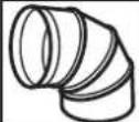
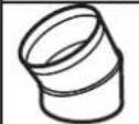
This microwave is designed for adaptation to three types of ventilation: outside top exhaust, outside back exhaust and non-venting ductless recirculation. Use the following duct instructions if the appliance will be vented to the outside.
For satisfactory air movement, the total duct length of 3 14 " x 10 " rectangular or 6 " round duct should not exceed 140 equivalent feet.
Elbows, transitions, wall caps and roof caps present additional resistance to airflow and are equivalent to a section of straight duct which is longer than the actual physical size. When calculating the total duct length add the equivalent lengths of all transitions and adapters plus the length of all straight duct sections. The chart below is an example of one possible installation configuration.
OUTSIDE TOP EXHAUST (EXAMPLE ONLY)
The following chart describes an example of one possible ductwork installation.
| DUCT PIECES EQUIVALENT | NT LENGTH | X | NUMBER USED | = | EQUIVALENT LENGTH | |
 | Roof cap | 24 ft X (1) = 2 | 4 ft | |||
| 12 ft. straight duct (6" round) | 12 ft X (1) = 1 | 2 ft | ||||
| Rectangular to round transition adapter | 5 ft X (1) = 5 ft | |||||
| TOTAL LENGTH | = 41 ft | |||||
IMPORTANT: If a rectangular to round transition adapter is used, the bottom corners of the damper must be cut to fit using tin snips to allow free movement of the damper.
IMPORTANT: It is important that venting be installed using the most direct route with as few elbows as possible. This ensures clear venting of exhaust and helps prevent blockages. Make sure dampers swing freely and nothing is blocking the ducts.
INSTALLATION INSTRUCTIONS
DUCT LENGTH CALCULATOR
Use the chart below to calculate the total length of the duct work being installed. The total length should not exceed 140 feet.
| DUCT PIECES EQUIVALENT | LENGTH | X | NUMBER USED | = | EQUIVALENT LENGTH | |
 | Rectangular to round transition adapter | 5 ft X ( | ) = ft | |||
 | Wall cap | 40 ft X ( | ) = ft | |||
 | Round 90° elbow | 10 ft X ( | ) = ft | |||
 | Round 45° elbow | 5 ft X ( | ) = ft | |||
 | Rectangular 90° elbow | 25 ft X ( | ) = ft | |||
 | Rectangular 45° elbow | 5 ft X ( | ) = ft | |||
 | Roof cap | 24 ft X ( | ) = ft | |||
| Straight duct 6" round or 3 1/4" x 10" rectangular | 1 ft X ( | ) = ft | ||||
| TOTAL LENGTH | = | f | ||||
INSTALLATION INSTRUCTIONS - OUTSIDE TOP EXHAUST
Use these instructions if the appliance will be vented to the outside through the top of the appliance.
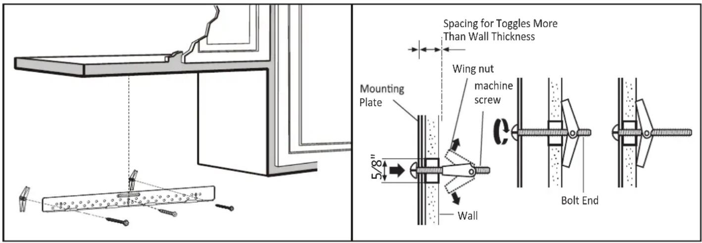
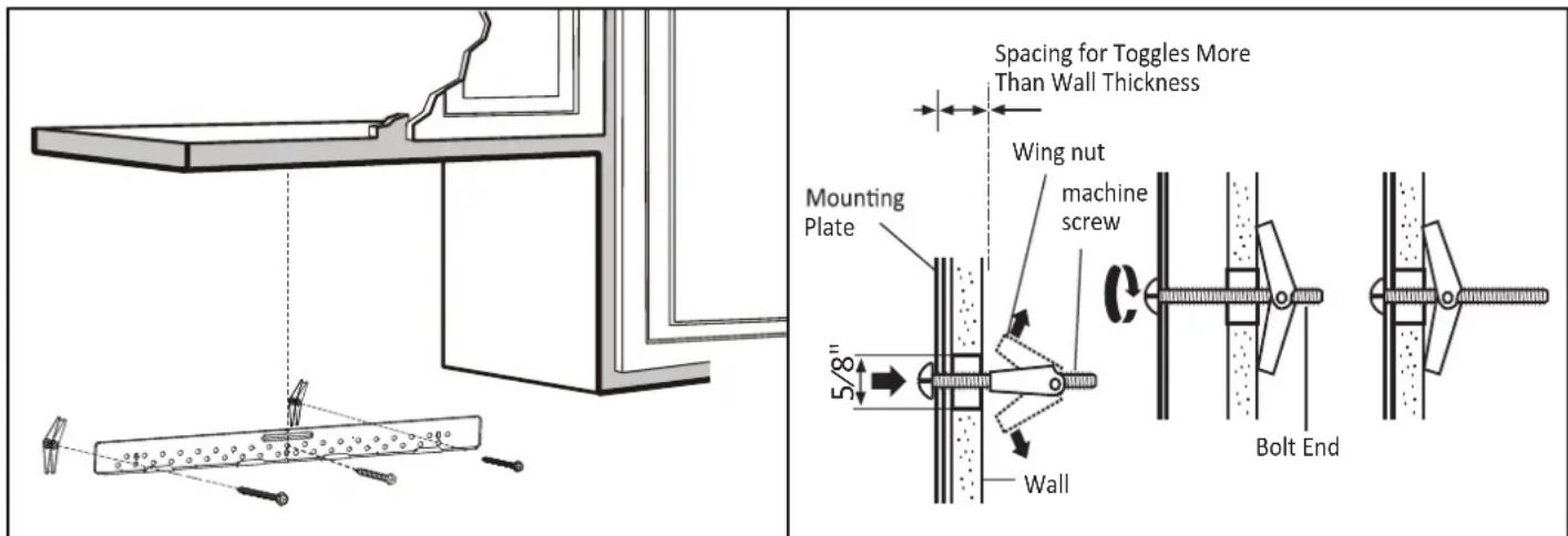
Install the mounting plate
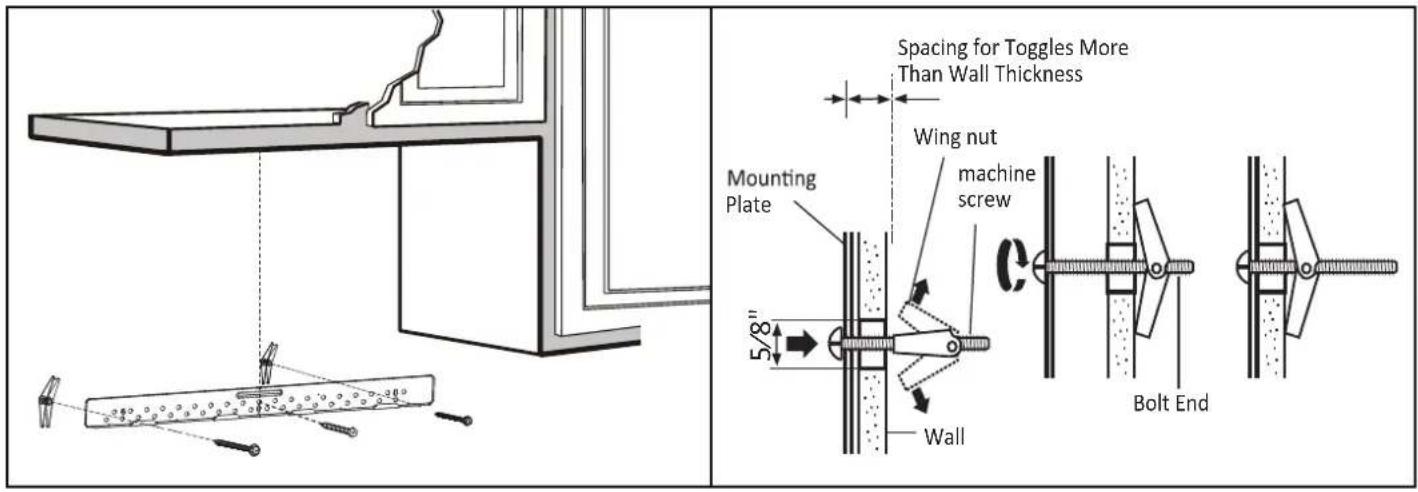
Use a 5/8" drill to make two holes that will enter the drywall. Use a 3/16" drill to make a hole that will enter a wall stud. Use the mounting template to decide the location of the holes. At least one hole must enter a wall stud.
Insert the machine screws into the mounting plate through the holes designed to go into drywall and attach the wing nuts 3/4" onto each machine screw.
Place the mounting plate against the wall and insert the wing nuts into the holes in the wall. The wing nuts will open on the other side of the wall to secure the screw.
Do not place a wing nut on the screw that will go into the wall stud. Insert a wood screw through the mounting plate and into the wall stud. Tighten all screws.
INSTALLATION INSTRUCTIONS - OUTSIDE TOP EXHAUST
Using the top cabinet template
There are instructions on the top cabinet template that detail how it should be used.
Tape the top cabinet template to the under side of the cabinet where the microwave will be installed.
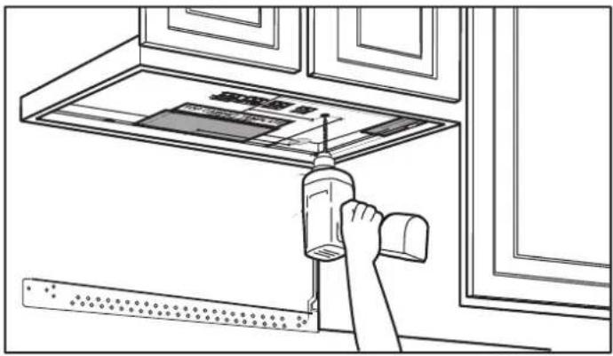
Drill holes for the top support screws, a hole large enough for the power cord to fit through and a cutout large enough for the exhaust adapter.
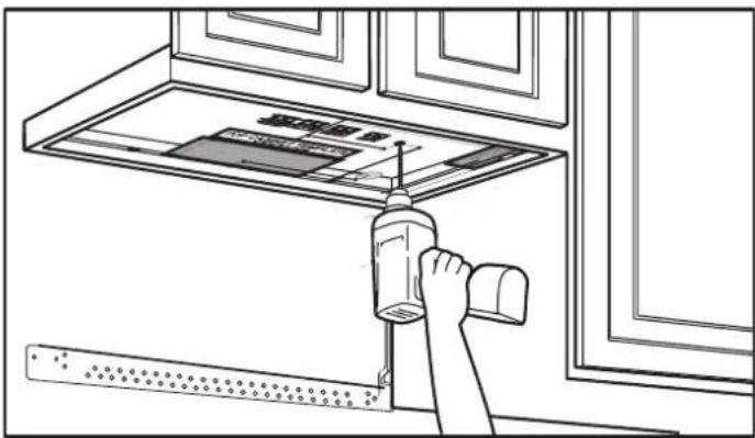
natural_image
Line drawing of a hand using a tool to clean or install a ceiling-mounted device (no text or symbols visible)Check for proper damper operation
Place the microwave in its upright position with the top of the appliance facing up.
Make sure the tape securing the damper is removed and the damper pivots easily before mounting the microwave.
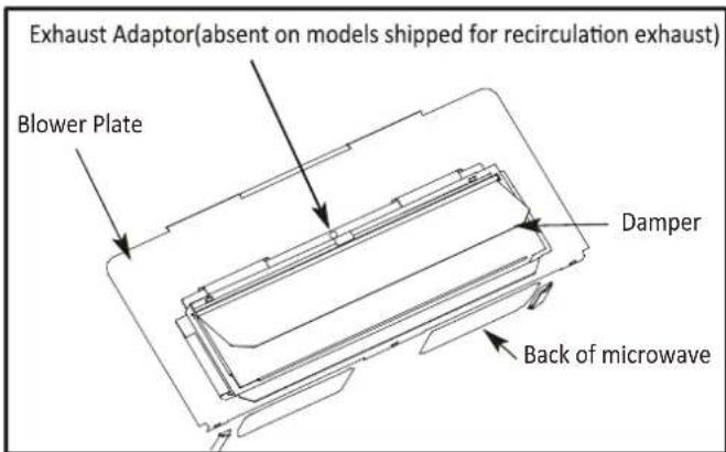
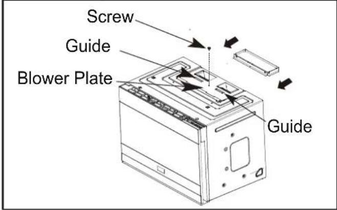
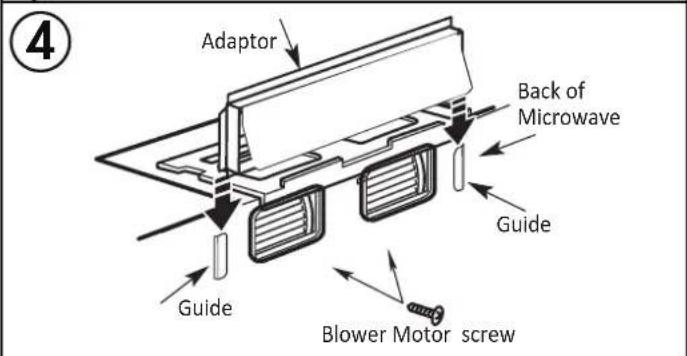
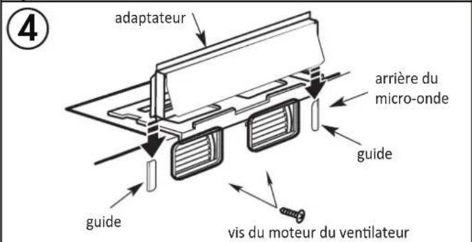
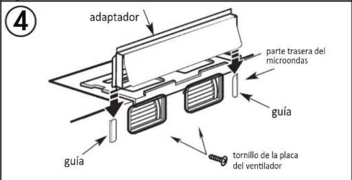
Attach the exhaust adapter to the blower plate by sliding it into the guides. Secure the adapter with one sheet metal screw.
INSTALLATION INSTRUCTIONS - OUTSIDE TOP EXHAUST
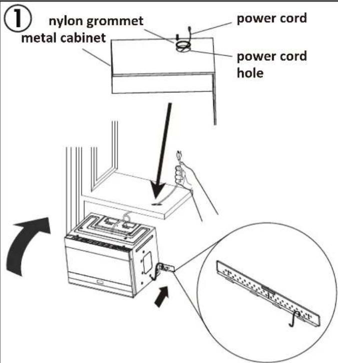
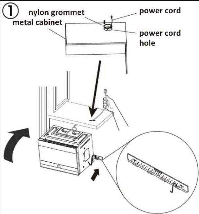
Mounting the microwave oven
Two people should be used to install the microwave. Do not grip or use the handle during installation.
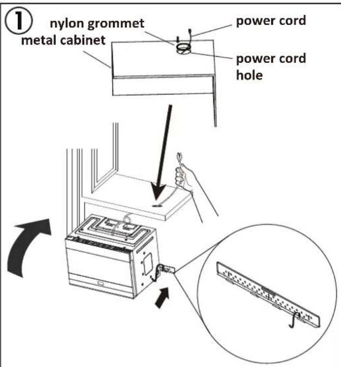
If the surrounding cabinets are metal, use the nylon grommet around the power cord hole to prevent damage to the cord.
When mounting the microwave, thread the power cord through the hole in the cabinet. Keep the cord tight when mounting the microwave to ensure the cord does not get pinched. Do not lift the microwave by the cord.
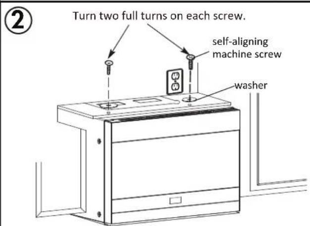
- Lift the microwave, tilt it forward and hook the slots on the back of the microwave onto the lower tabs of the mounting plate. Rotate the front of the microwave against the bottom of the cabinet.
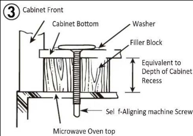
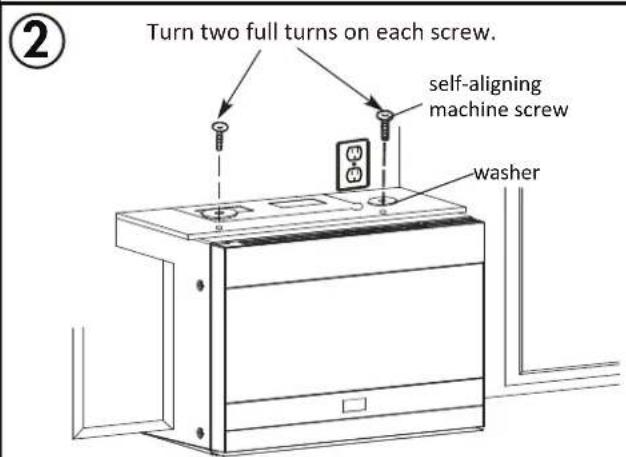
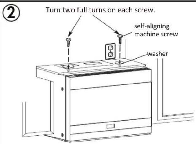
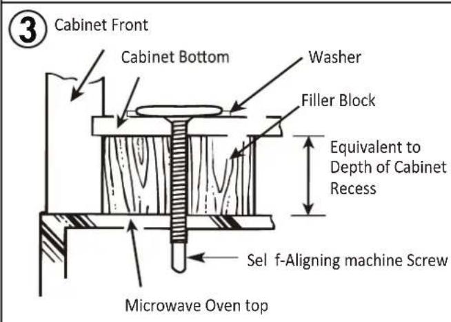
- Insert two self aligning machine screws with washers through the top cabinet holes and tighten two turns.
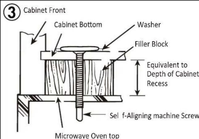
- If the cabinet has an overhang, insert the wood filler blocks before completely tightening the screws.
INSTALLATION INSTRUCTIONS - OUTSIDE TOP EXHAUST
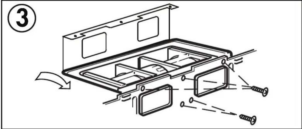
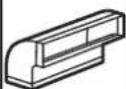
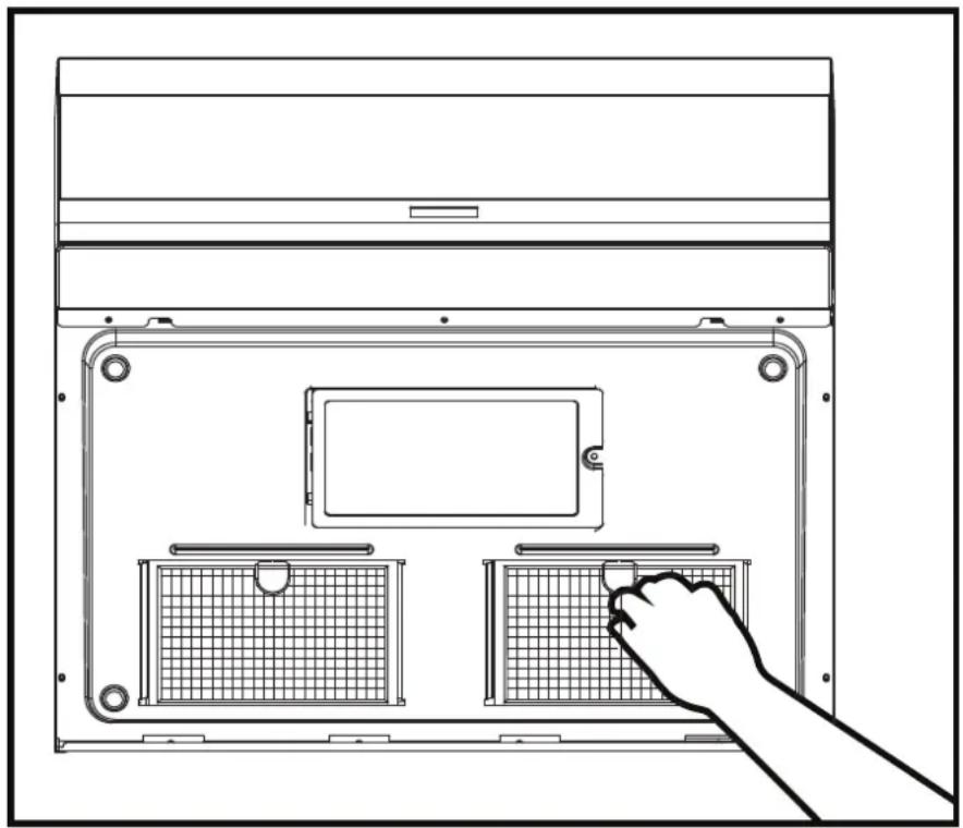
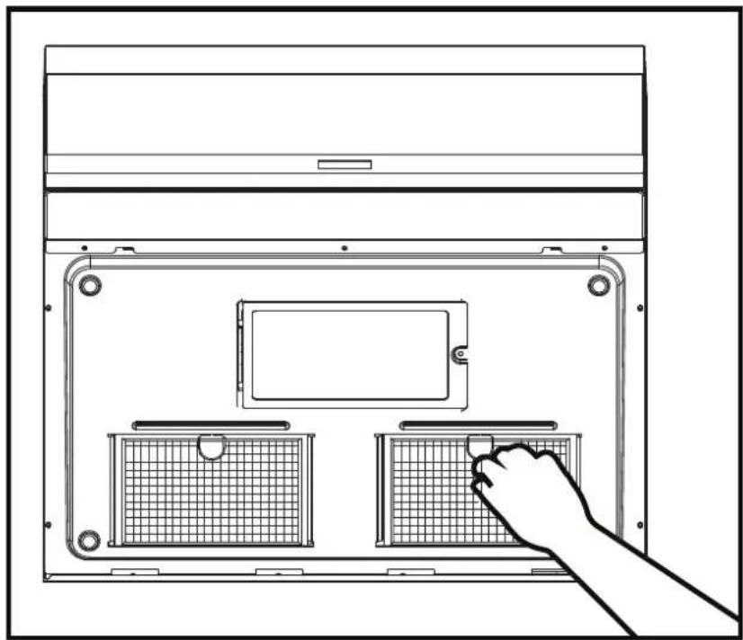
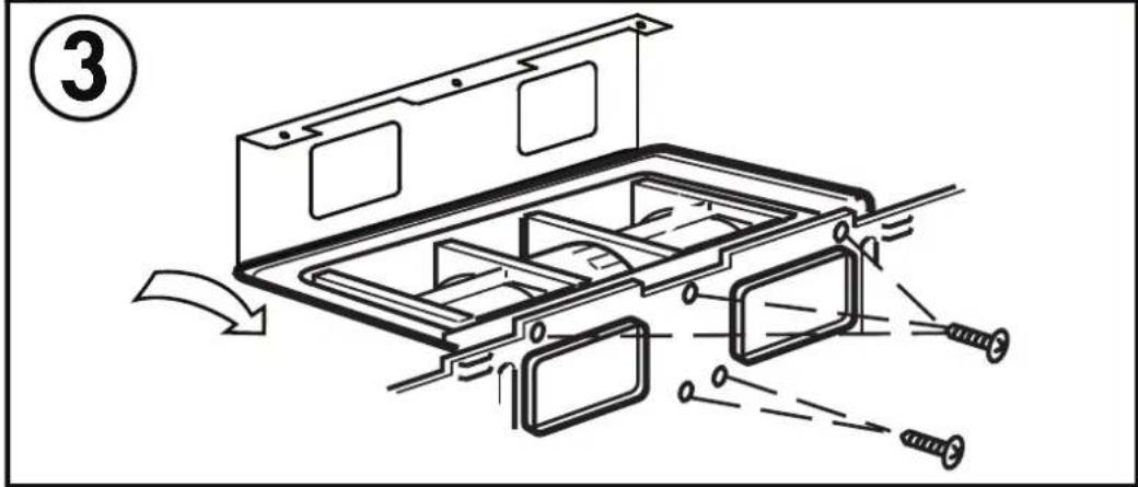
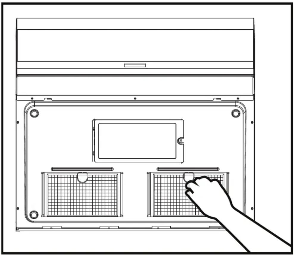
Install grease fi Iters
Slide the grease fi Iters into the openings in the bottom of the microwave until they click into place. The appliance should not be operated without the grease fi Iters installed.
natural_image
Line drawing of a laptop front panel with two internal compartments and a hand pointing to the screen (no text or symbols)Connecting ductwork
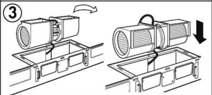
Adjust the exhaust adapter inside the cabinet so it can connect to the house duct.
Extend the house duct down to connect to the exhaust adapter.
Use duct tape to seal the exhaust duct joints.
INSTALLATION INSTRUCTIONS - OUTSIDE BACK EXHAUST
Use these instructions if the appliance will be vented to the outside through the back of the appliance.
Cut a 12" x 4" square hole in the rear wall for the outside exhaust. Follow the instructions included on the rear template.
Install the mounting plate
Use a 5/8" drill to make two holes that will enter the drywall. Use a 3/16" drill to make a hole that will enter a wall stud. Use the mounting template to decide the location of the holes. At least one hole must enter a wall stud.
Insert the machine screws into the mounting plate through the holes designed to go into drywall and attach the wing nuts 3/4" onto each machine screw.
Place the mounting plate against the wall and insert the wing nuts into the holes in the wall. The wing nuts will open on the other side of the wall to secure the screw.
Do not place a wing nut on the screw that will go into the wall stud. Insert a wood screw through the mounting plate and into the wall stud. Tighten all screws.
INSTALLATION INSTRUCTIONS - OUTSIDE BACK EXHAUST
Using the top cabinet template
There are instructions on the top cabinet template that detail how it should be used.
Tape the top cabinet template to the under side of the cabinet where the microwave will be installed.
Drill holes for the top support screws, a hole large enough for the power cord to fit through and a cutout large enough for the exhaust adapter.
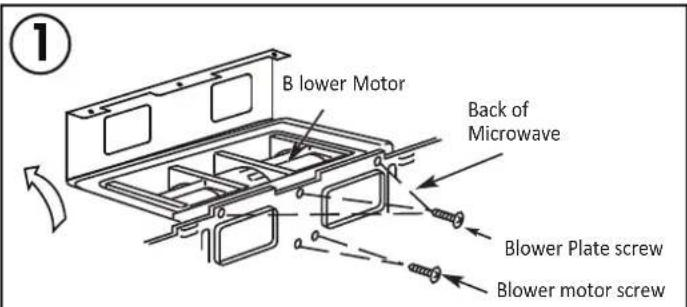
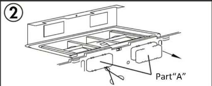
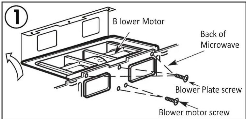
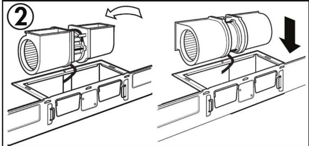
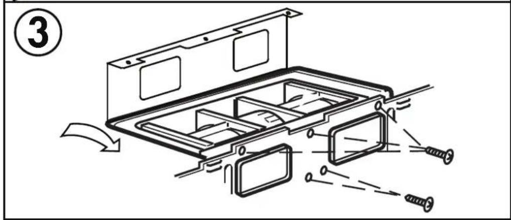
Adapting blower for back exhaust
- Remove the screws that secure the blower motor. Lift up the blower plate.
- Remove part A with tin snips or scissors.
- Pull out the blower unit. Be careful not to stretch the wires and make sure the wires do not get pinched. Rotate the blower so that it faces toward the back and replace it in the appliance. The blower unit exhaust openings should match the exhaust openings on the rear of the microwave.
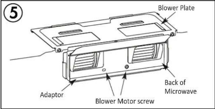
- Close the blower plate. Attach the exhaust adapter to the back of the microwave by sliding it into the guides at the top. Push in securely until the screw holes are visible. Ensure that the damper hinge is installed so that it is at the top and the damper swings freely.
- Secure the blower motor with screws. Secure the blower plate with screws.

INSTALLATION INSTRUCTIONS - OUTSIDE BACK EXHAUST
Mounting the microwave oven
Two people should be used to install the microwave. Do not grip or use the handle during installation.
If the surrounding cabinets are metal, use the nylon grommet around the power cord hole to prevent damage to the cord.
When mounting the microwave, thread the power cord through the hole in the cabinet. Keep the cord tight when mounting the microwave to ensure the cord does not get pinched. Do not lift the microwave by the cord.
- Lift the microwave, tilt it forward and hook the slots on the back of the microwave onto the lower tabs of the mounting plate. Rotate the front of the microwave against the bottom of the cabinet.
- Insert two self aligning machine screws with washers through the top cabinet holes and tighten two turns.
- If the cabinet has an overhang, insert the wood filler blocks before completely tightening the screws.
INSTALLATION INSTRUCTIONS - OUTSIDE BACK EXHAUST
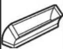
Install grease fi Iters
Slide the grease fi Iters into the openings in the bottom of the microwave until they click into place. The appliance should not be operated without the grease fi Iters installed.

natural_image
Line drawing of a laptop front panel with two internal compartments and a hand inserting a button (no text or symbols)Connecting ductwork
Adjust the exhaust adapter inside the cabinet so it can connect to the house duct.
Extend the house duct down to connect to the exhaust adapter.
Use duct tape to seal the exhaust duct joints.
INSTALLATION INSTRUCTIONS - RECIRCULATING (NON-VENTED)
Use these instructions if the appliance will not be vented to the outside.
Install the mounting plate
Use a 5/8" drill to make two holes that will enter the drywall. Use a 3/16" drill to make a hole that will enter a wall stud. Use the mounting template to decide the location of the holes. At least one hole must enter a wall stud.
Insert the machine screws into the mounting plate through the holes designed to go into drywall and attach the wing nuts 3/4" onto each machine screw.
Place the mounting plate against the wall and insert the wing nuts into the holes in the wall. The wing nuts will open on the other side of the wall to secure the screw.
Do not place a wing nut on the screw that will go into the wall stud. Insert a wood screw through the mounting plate and into the wall stud. Tighten all screws.
Using the top cabinet template
There are instructions on the top cabinet template that detail how it should be used.
Tape the top cabinet template to the under side of the cabinet where the microwave will be installed.
Drill holes for the top support screws, a hole large enough for the power cord to fit through and a cutout large enough for the exhaust adapter.
INSTALLATION INSTRUCTIONS - RECIRCULATING (NON-VENTED)
Adapting blower for recirculating exhaust
- Remove the screws that secure the blower motor. Lift up the blower plate.
- Pull out the blower unit. Be careful not to stretch the wires and make sure the wires do not get pinched. Rotate the blower so that it faces toward the front and replace it in the appliance.
- Secure the blower motor with screws. Secure the blower plate with screws.
INSTALLATION INSTRUCTIONS - RECIRCULATING (NON-VENTED)
Mounting the microwave oven
Two people should be used to install the microwave. Do not grip or use the handle during installation.
If the surrounding cabinets are metal, use the nylon grommet around the power cord hole to prevent damage to the cord.
When mounting the microwave, thread the power cord through the hole in the cabinet. Keep the cord tight when mounting the microwave to ensure the cord does not get pinched. Do not lift the microwave by the cord.
- Lift the microwave, tilt it forward and hook the slots on the back of the microwave onto the lower tabs of the mounting plate. Rotate the front of the microwave against the bottom of the cabinet.
- Insert two self aligning machine screws with washers through the top cabinet holes and tighten two turns.
- If the cabinet has an overhang, insert the wood filler blocks before completely tightening the screws.
INSTALLATION INSTRUCTIONS - RECIRCULATING (NON-VENTED)
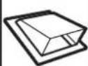
Install grease filters
Slide the grease fi Iters into the openings in the bottom of the microwave until they click into place. The appliance should not be operated without the grease fi Iters installed.
natural_image
Line drawing of a laptop back panel with two internal compartments and a hand adjusting the front panel (no text or symbols)Air recirculation
There is no duct work required for this type of installation. Air from the appliance will exhaust through the front vent and recirculate into the air in the room.
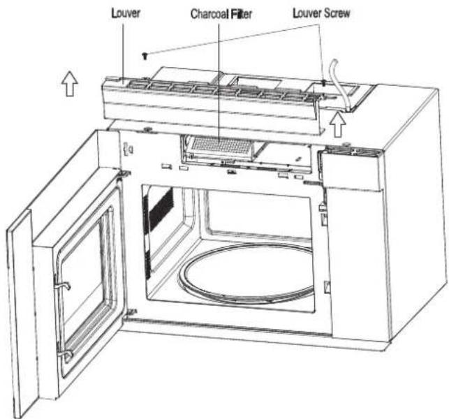
Charcoal fi Iter
The charcoal fi Iter should be used in non-vented, recirculating installations. The fi Iter should be changed every 6 to 12 months depending on use.
- Remove the two screws securing the louver on the front of the microwave.
- Remove the used charcoal filter.
- Install the new charcoal fi lter. The wire mesh of the fi lter should be visible from the front.
- Reinstall the louver.
To purchase replacement fi liters, either contact the consumer service department or visit www.DanbyApplianceParts.com or www.DanbyApplianceParts.ca
INTERFÉRENCES DE FRÉQUENCE RADIO
TROUVER LES POTEAUX MURAUX
natural_image
Illustration of a hand holding a pen, with arrows indicating direction and alignment (no text or symbols)INSTRUCTIONS D'INSTALLATION
UTILISATION DU MODÈLE D'INSTALLATION
MODÈLE ENDOMMAGÉ OU INUTILISABLE
other
| Dimension | Value (cm) | | :--- | :--- | | Top Section | 16 17/25" (42.4 cm) (43.5 cm) | | Middle Section | 9 9/25" (23.8 cm) | | Bottom Section | 9 9/25" (23.8 cm) | | Right Section | 17 1/8 | The chart displays a grid layout with four horizontal lines representing different measurement scales.REMARQUES
natural_image
Technical line drawing of a mechanical assembly with mounting bracket and supporting components (no text or symbols)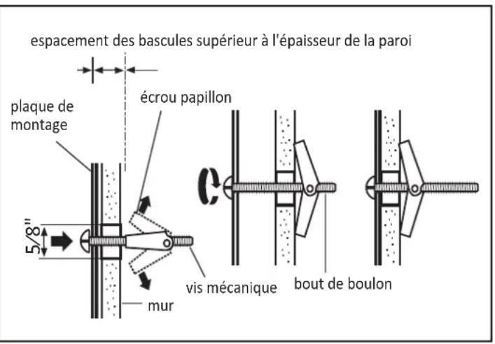
natural_image
Line drawing of a hand using a tool to clean or install a ceiling-mounted device (no text or symbols visible)natural_image
Line drawing of a laptop front panel with two internal compartments and a hand pointing to the screen (no text or symbols)natural_image
Technical line drawing of a mechanical assembly with mounting bracket and base plate (no text or symbols)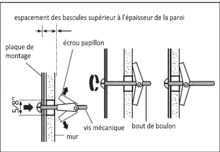

natural_image
Line drawing of a laptop front panel with two internal compartments and a hand adjusting the screen (no text or symbols)natural_image
Technical line drawing of a mechanical assembly with mounting bracket and support structure (no text or symbols)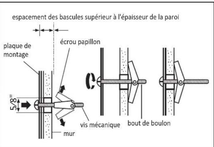
natural_image
Line drawing of a hand using a tool to clean or install a ceiling-mounted device (no text or symbols visible)INSTRUCTIONS D'INSTALLATION - RECIRCULATION (NON VENTILÉ)
INSTRUCTIONS D'INSTALLATION - RECIRCULATION (NON VENTILÉ)
natural_image
Line drawing of a laptop front panel with two internal compartments and a hand adjusting the screen (no text or symbols)Recirculation d'air
ENCONTRAR LOS MONTANTES DE LA PARED
natural_image
Illustration of a hand holding a pen, with arrows indicating direction and alignment (no text or symbols)There are three different types of cabinetry that will change how the rear wall template should be used to determine where to install the mounting bracket.
other
| Dimension | Value | | :--- | :--- | | Top Section | 16 17/25" (42.4 cm) (43.5 cm) | | Middle Section | 9 9/25" (23.8 cm) | | Bottom Section | 9 9/25" (23.8 cm) | | Right Section | 17 1/8 | The chart displays a schematic layout with four vertical segments and two horizontal segments, each annotated with a numerical value and a circular symbol indicating the length of the top section.NOTAS
natural_image
Line drawing of a hand using a tool to clean or install a ceiling-mounted device (no text or symbols visible)natural_image
Line drawing of a laptop case with two internal compartments and a hand pointing to one (no text or symbols)natural_image
Technical line drawing of a mechanical assembly with mounting bracket and support structure (no text or symbols)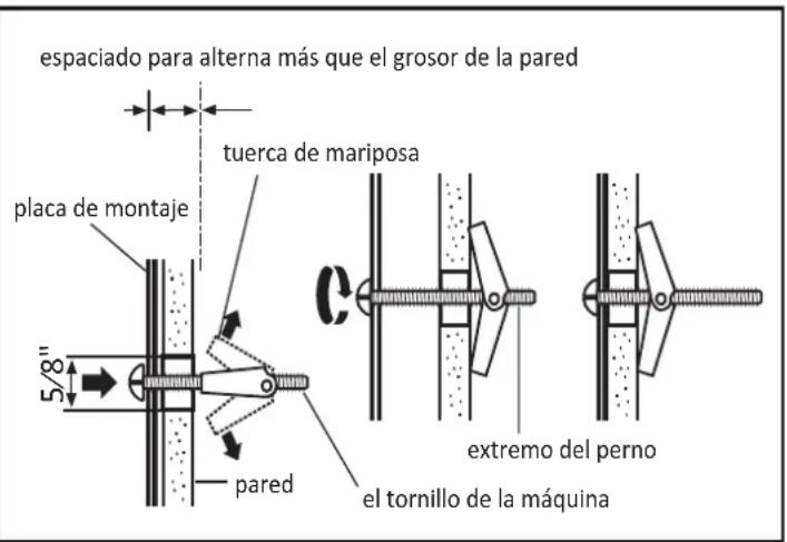
Install grease fi Iters
Slide the grease filters into the openings in the bottom of the microwave until they click into place. The appliance should not be operated without the grease filters installed.
natural_image
Line drawing of a laptop front panel with two internal compartments and a hand inserting a button (no text or symbols)Connecting ductwork
Adjust the exhaust adapter inside the cabinet so it can connect to the house duct.
Extend the house duct down to connect to the exhaust adapter.
Use duct tape to seal the exhaust duct joints.
Use these instructions if the appliance will not be vented to the outside.
natural_image
Line drawing of a hand using a tool to clean or install a ceiling-mounted device (no text or symbols visible)