MTX 202 - Multimeter METRIX - Free user manual and instructions
Find the device manual for free MTX 202 METRIX in PDF.
Pick your language and provide your email: we'll send you a specifically translated version.
| Product type | Digital multimeter |
| Brand | Metrix |
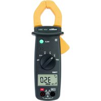
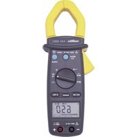
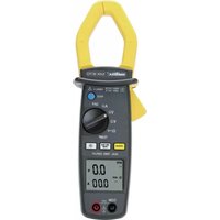
| Model | MTX 202 |
| Dimensions | 180 x 80 x 40 mm |
| Weight | 300 g (with batteries) |
| Power supply | 2 AAA 1.5 V batteries |
| Maximum measurable voltage | 600 V AC/DC |
| Maximum measurable current | 10 A AC/DC |
| Measurement functions | AC/DC voltage, AC/DC current, resistance, capacitance, frequency, diode test, continuity test |
| Display | 4000-count LCD screen |
| Safety category | CAT II 600 V |
| Protection fuse | 10 A / 600 V fuse |
| Battery type | 2 AAA 1.5 V batteries |
| Care and cleaning | Clean with a soft, dry cloth. Do not use solvents. |
| Available spare parts | Batteries, fuses, test leads |
| Repairability | Repairable by a professional: accessible fuses and batteries |
Frequently Asked Questions - MTX 202 METRIX
How to measure DC voltage with the MTX 202?
Turn the switch to the V (DC voltage) position. Connect the red lead to the V/Ω terminal and the black lead to COM. Place the test probes in parallel with the circuit. Read the value on the LCD screen.
How to measure current up to 10 A?
Insert the red lead into the 10A (max) terminal and the black lead into COM. Select the A (current) function and the appropriate range. Connect the multimeter in series with the circuit. Do not exceed 10 A.
What does the 'OL' display mean?
'OL' means Over Load. The measurement exceeds the selected range. Select a higher range or check that the circuit is not overvoltage.
How to test continuity of a circuit?
Turn the switch to the continuity test position (diode or wave symbol). Connect the leads as for a resistance measurement. If the circuit is closed, a beep sounds and the resistance is displayed.
When to replace the batteries of the MTX 202?
When the low battery icon appears on the screen, replace both AAA batteries with new ones. Open the compartment on the back of the device.
How to change the fuse?
Disconnect the test leads. Open the battery compartment and remove the defective fuse. Replace it with an identical fuse: 10 A / 600 V.
What safety precautions should be taken?
Never measure voltages above 600 V. Use test leads in good condition. Respect safety categories (CAT II). Do not touch the metal tips during measurements.
How to clean the multimeter?
Turn off the device and remove the batteries. Clean the housing with a soft, dry cloth. Do not use chemicals or abrasives.
What to do if the screen does not turn on?
Check the battery condition (replace if necessary). Ensure the switch is on a measurement position. If the problem persists, contact customer service.
Can I measure AC voltage with this model?
Yes, select the V~ (AC voltage) position. The test leads are connected the same way as for DC voltage. Read the RMS value on the screen.
User questions about MTX 202 METRIX
0 question about this device. Answer the ones you know or ask your own.
Ask a new question about this device
No questions yet. Be the first to ask one.
Download the instructions for your Multimeter in PDF format for free! Find your manual MTX 202 - METRIX and take your electronic device back in hand. On this page are published all the documents necessary for the use of your device. MTX 202 by METRIX.