eXcellence 620 - Sewing machine ELNA - Free user manual and instructions
Find the device manual for free eXcellence 620 ELNA in PDF.



User questions about eXcellence 620 ELNA
0 question about this device. Answer the ones you know or ask your own.
Ask a new question about this device
Download the instructions for your Sewing machine in PDF format for free! Find your manual eXcellence 620 - ELNA and take your electronic device back in hand. On this page are published all the documents necessary for the use of your device. eXcellence 620 by ELNA.
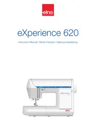
USER MANUAL eXcellence 620 ELNA
natural_image
Illustration of a sewing machine labeled '620' with eXperience 620 branding, no visible text or symbols beyond branding and model name.IMPORTANT SAFETY INSTRUCTIONS
This appliance is not intended for use by persons (including children) with reduced physical, sensory or mental capabilities, or lack of experience and knowledge, unless they have been given supervision or instruction concerning use of the appliance by a person responsible for their safety.
Children should be supervised to ensure that they do not play with this sewing machine.
When using an electrical appliance, basic safety precautions should always be followed, including the following :
This sewing machine is designed and manufactured for household use only.
Read all instructions before using this sewing machine.
DANGER — To reduce the risk of electric shock:
-
An appliance should never be left unattended when plugged in. Always unplug this sewing machine from the electric outlet immediately after using and before cleaning.
-
Always unplug before replacing a sewing machine bulb. Replace bulb with same type rated 12 Volts, 5 Watts.
WARNING — To reduce the risk of burns, fire, electric shock, or injury to persons:
- Do not allow to be used as a toy. Close attention is necessary when this sewing machine is used by or near children.
- Use this appliance only for its intended use as described in this owner's manual. Use only attachments recommended by the manufacturer as contained in this owner's manual.
- Never operate this sewing machine if it has a damaged cord or plug, if it is not working properly, if it has been dropped or damaged, or dropped into water. Return this sewing machine to the nearest authorized dealer or service center for examination, repair, electrical or mechanical adjustment.
- Never operate the appliance with any air opening blocked. Keep ventilation openings of this sewing machine and foot controller free from accumulation of lint, dust and loose cloth.
- Never drop or insert any object into any opening.
- Do not use outdoors.
- Do not operate where aerosol (spray) products are being used or where oxygen is being administered.
- To disconnect, turn all controls to the off ("O") position, then remove plug from outlet.
- Do not unplug by pulling on cord. To unplug, grasp the plug, not the cord.
- Keep fingers away from all moving parts. Special care is required around the sewing machine needle and/or cutting blade.
- Always use the proper needle plate. The wrong plate can cause the needle to break.
- Do not use bent needles.
- Do not pull or push fabric while stitching. It may deflect the needle causing it to break.
- Switch this sewing machine off ("O") when making any adjustment in the needle area, such as threading the needle, changing the needle, threading the bobbin or changing the presser foot, and the like.
- Always unplug this sewing machine from the electrical outlet when removing covers, lubricating, or when making any other adjustments mentioned in this owner's manual.
SAVE THESE INSTRUCTIONS
The design and specifications are subject to change without a prior notice.

Please note that on disposal, this product must be safely recycled in accordance with relevant National legislation relating to electrical/electronic products. If in doubt please contact your retailer for guidance. (European Union only)
USA only
Your machine comes equipped with a polarized plug (one prong wider than the other). A polarized plug reduces the risk of electrical shock. This plug is intended to fit into a polarized outlet. If the plug does not fit fully into the outlet, reverse the plug. If it still does not fit, contact a qualified electrician to install the proper outlet. Do not modify the plug in any way.
Use only foot control model 21371 for this sewing machine (UL, CSA).
TABLE OF CONTENTS
SECTION I – Machine Parts and Functions
Part Names ....3
Standard Accessories 4
Presser Foot and Accessory Definitions... .5-6
Extension Table and Free Arm 6
Circular Sewing Pivot Points 7
Using the Fine Adjustment Screw....7
How to Drop the Feed Dog 7
Foot Pressure Dial 8
Presser Foot Lever and Additional
Presser Foot Clearance 8
Attaching and Removing Presser Feet .....8
Attaching and Removing Shank 9
Seam Allowance Lines 9
Controlling Sewing Speed 9
Adjusting Needle Thread Tension.... 10
SECTION II – Getting Ready to Sew
Connecting Machine to Power Supply .....11
Selecting the Correct Needle and Thread ...12
Changing Needles 12
Needle Definitions 13
Keys and LED Readout 14-16
Winding a Bobbin .....17-18
Additional Spool Pin 18
Inserting the Bobbin 19
Threading the Machine....20
Built-in Needle Threader ....21
Drawing Up the Bobbin Thread .....22
Buttonhole Variations....23-24
SECTION III – Taking Care of Your Machine
Cleaning the Bobbin Area 25
Cleaning the Hook Area and Feed Dog . 25-26
Replacing the Bobbin Case.... 26
Changing the Light Bulb 26
STITCH CHART 27
OPTIONAL ACCESSORIES 28
TROUBLESHOOTING .....29
INDEX.... 30
NOTE: In formation found in this instruction manual is current at the time of printing. Elna reserves the right to change and update specifications and information as needed.
text_image
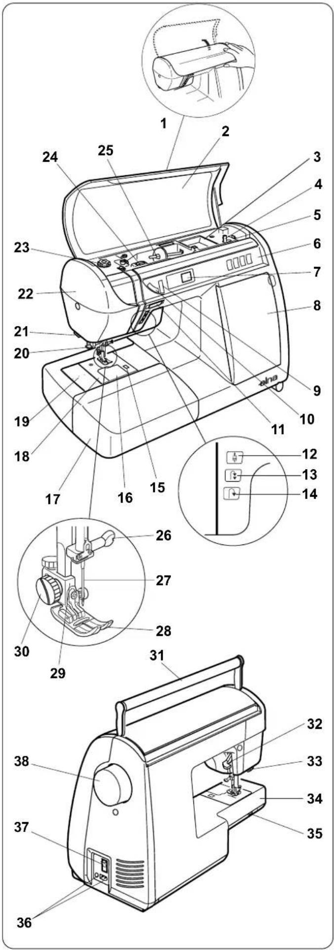
Technical diagram of a sewing machine with numbered parts and close-ups of the internal components.SECTION I
Machine Parts and Functions
Part Names
- Top cover (lift up and back)
- Stitch chart
- Top storage compartment
- Bobbin winder spindle
- Bobbin winder stop
- Selection keys
- LED readout
- Side storage compartment
- Stitch length key
- Stitch width key
- Speed control lever
- Up/down needle key
- Auto-lock key
- Reverse key
- Bobbin cover plate release button
- Bobbin cover plate
- Extension table (storage box)
- Needle plate
- Circular sewing pivot points
- Needle threader
- Thread cutter
- Face plate
- Foot pressure dial
- Needle thread tension dial
- Spool pin
- Needle clamp screw
- Needle
- Presser foot
- Shank
- Thumbscrew
- Carrying handle
- Presser foot lever
- Buttonhole lever
- Free arm
- Feed dog lever
- Machine sockets
- Power switch
- Flywheel (always turn towards you)
text_image
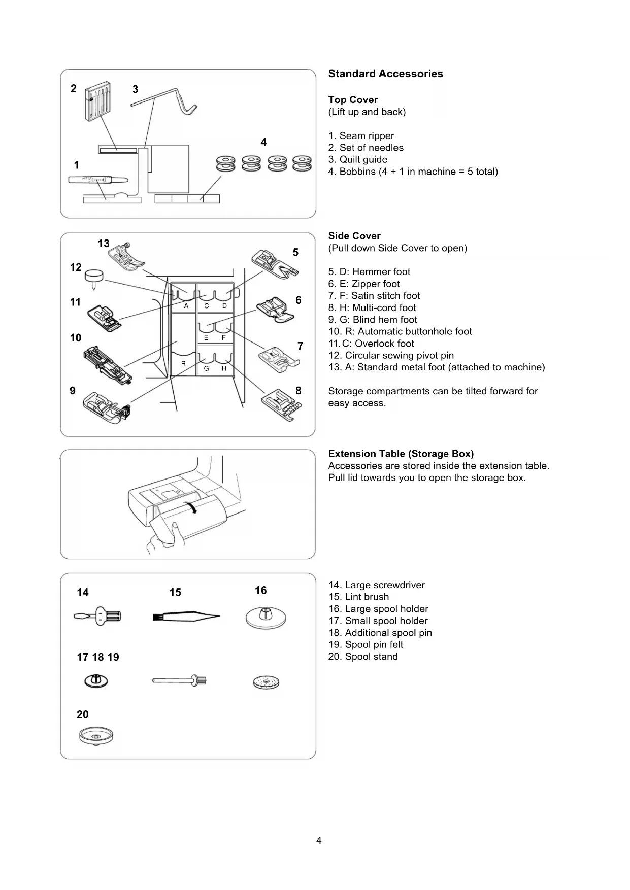
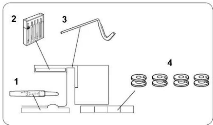
Technical diagram of a mechanical assembly with labeled components and numbered partsStandard Accessories
Top Cover
(Lift up and back)
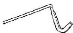
- Seam ripper
- Set of needles
- Quilt guide
- Bobbins (4 + 1 in machine = 5 total)
text_image
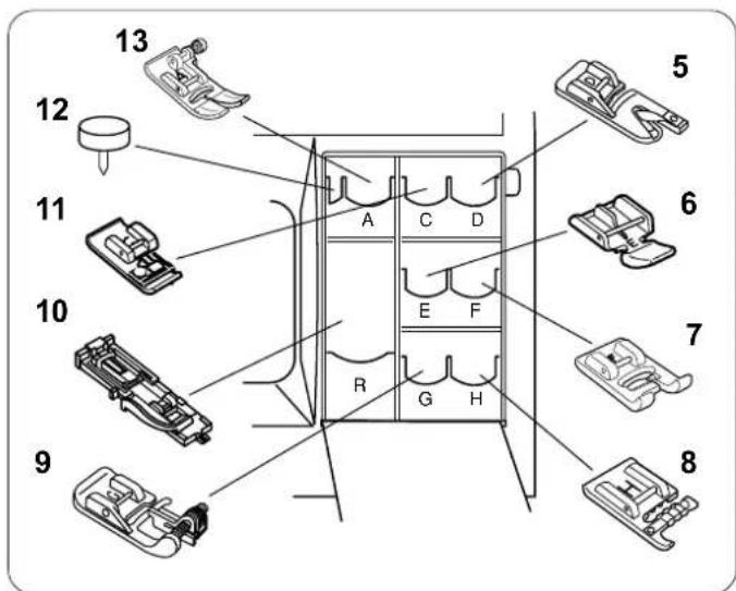
13 12 11 10 9 5 6 7 8 A C D E F R G HSide Cover
(Pull down Side Cover to open)
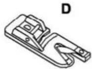
- D: Hemmer foot
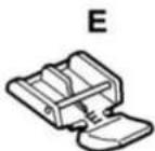
- E: Zipper foot
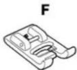
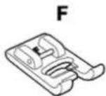
- F: Satin stitch foot
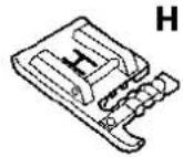
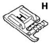
- H: Multi-cord foot
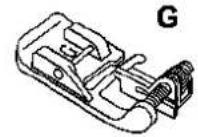
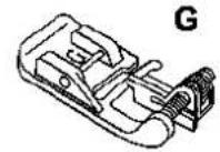
- G: Blind hem foot
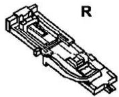
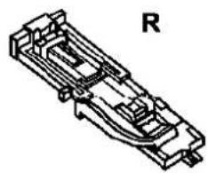
- R: Automatic buttonhole foot
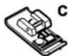
- C: Overlock foot
- Circular sewing pivot pin
- A: Standard metal foot (attached to machine)
Storage compartments can be tilted forward for easy access.
natural_image
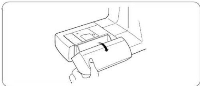
Line drawing of a hand holding a device with a scroll wheel (no text or symbols)Extension Table (Storage Box)
Accessories are stored inside the extension table. Pull lid towards you to open the storage box.
text_image
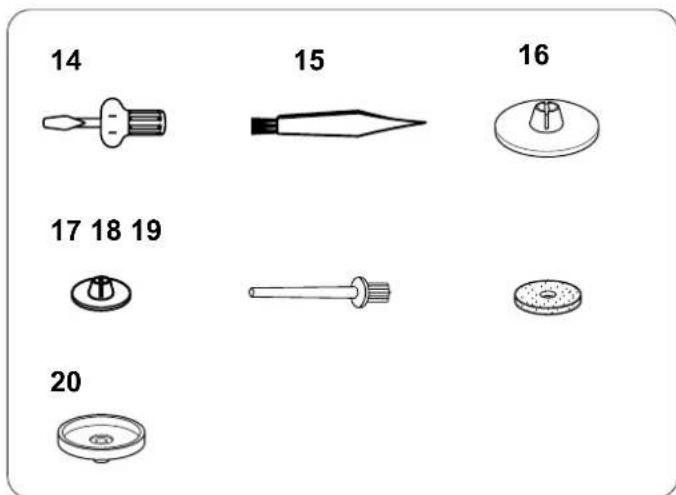
14 15 16 17 18 19 20- Large screwdriver
- Lint brush
- Large spool holder
- Small spool holder
- Additional spool pin
- Spool pin felt
- Spool stand
21
22
23
24
natural_image
Simple line drawing of a bag with 'elna' branding and handle (no additional text or symbols)25
natural_image
Pure technical line drawing of a mechanical bracket or housing (no text or symbols)Machine Box
- Instruction book
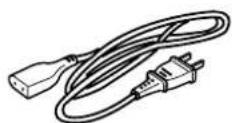
- Power supply cord
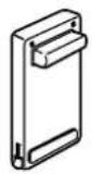
- Foot control
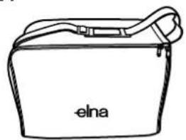
- Carrying bag
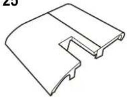
- Quilt table
Presser Foot and Accessory Definitions
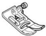
A: Standard Metal Foot
This foot comes attached to your machine. It is mainly used for straight stitches and zigzag stitches longer than 1.0. The button locks the foot in a horizontal position helping to sew over multiple layered seams.
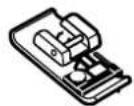
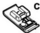
C: Overlock Foot
Prevent fabric edges from raveling by finishing the edge with a zigzag stitch. The wires/brush on the foot help the stitch lie flatter and reduce puckering. Use with medium weight fabrics.
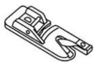
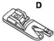
D: Hemmer Foot
Insert the fabric into the spiral on this foot. The spiral rolls the fabric, creating a rolled hem. An easy, professional way to sew hems.
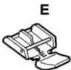
E: Zipper Foot
Use when sewing zippers into place. The grooves on the underside ensure the foot glides over the zipper coil. Attach either to the left or right of the needle to sew each side of the zipper.
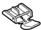
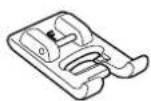
F: Satin Stitch Foot
The cutout on the underside of the foot is designed to accommodate dense stitch formation. Ideal when sewing satin and decorative stitches.
A
C
D
E
F
natural_image
Technical line drawing of a mechanical component with no visible text or symbols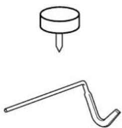
natural_image
Simple line drawing of a pin and a hook (no text or symbols)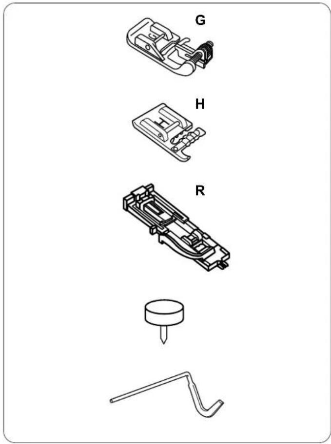
text_image
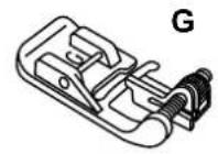
G H RG: Blind Hem Foot
The guide on the foot helps ensure that the needle catches only one or two fibers of the hem, resulting in an invisible hemline.
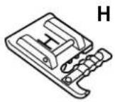
H: Multi-Cord Foot
Design your own braids or trims. Place one to three cords in the foot and sew over cord(s) for a simple couching method. Or sew over one cord with a zigzag to gather heavier weight fabrics.
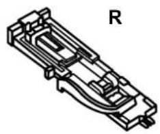
R: Automatic Buttonhole Foot
Place button in foot to determine the buttonhole size. The machine will automatically sew the corresponding buttonhole.
Circular Sewing Pivot Pin
The free arm has holes that are 1 cm apart from each other. Use this pivot pin to secure the fabric and sew perfect curves or circles or large scallops.
Quilt Guide
The quilt guide is helpful when sewing parallel, evenly spaced rows of stitching.
natural_image
Line drawing of a hand inserting a component into a device (no text or symbols)Extension Table and Free Arm
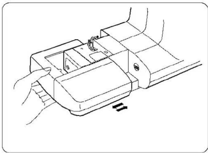
Extension Table
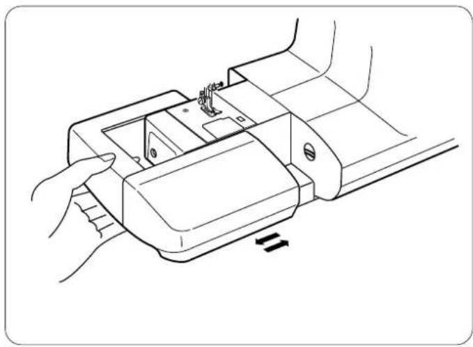
The extension table provides more sewing space to make sewing easier. The extension table can be easily removed for free arm sewing.
To Remove:
Pull the end of the extension table away from the machine, as shown.
To Attach:
Push the table back into place to reattach the extension table.
natural_image
Line drawing of a hand using a sewing machine to adjust or install a mechanical component (no text or symbols present)Free Arm
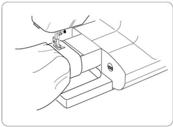
Free arm sewing is good for circle areas like sleeves, waistbands and pant legs. If socks, knee or elbow areas need mending, the free arm will be best to use.
natural_image
Line drawing of a car interior with a numbered component (no text or symbols)Circular Sewing Pivot Points
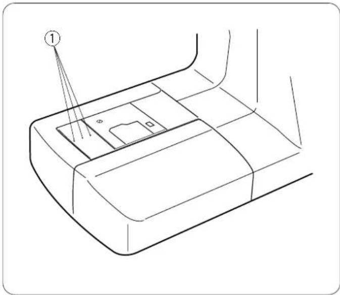
The free arm has holes ① that are 1 cm apart from each other. Use the holes to sew circles and scallops with the circular sewing pivot pin.
text_image
Diagram illustrating the process of a device with labeled components and corresponding schematic diagrams showing (+) and (-) state transitions.Using the Fine Adjustment Screw
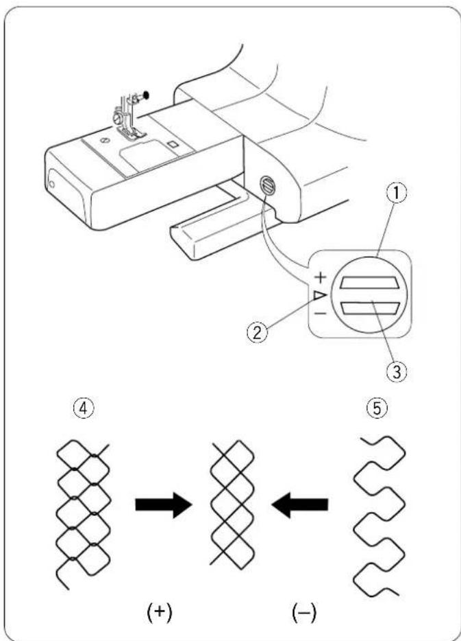
Choice of fabrics and threads may affect the stitch formation. The fine adjustment screw can be used to either lengthen or shorten the stitch.
① Fine adjustment screw
② Standard mark
③ Setting mark
To fine tune, use a screwdriver to move the setting mark.
- If stitches are too short ④, correct by turning the screw in the direction of “+”.
- If the stitches are too long ⑤, correct by turning the screw in the direction of “—”.
text_image
Diagram showing sewing process with labeled parts ① and ②, indicating fabric application stepsHow To Drop the Feed Dog
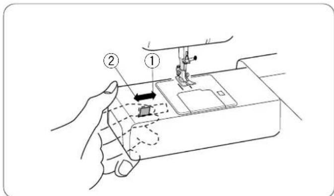
The feed dog can be dropped out of position for special sewing techniques: free motion embroidery, stippling, button sewing, etc.
The feed dog must always be up for regular sewing.
Locate the feed dog lever on the back of the free arm. Slide the lever either to the right (down) ① or to the left (up) ②. To bring up the feed dog, hand turn the flywheel after sliding lever to the left.
text_image
Technical diagram showing a hand operating a mechanical component with labeled parts ① and ②, including a magnified inset view.Foot Pressure Dial
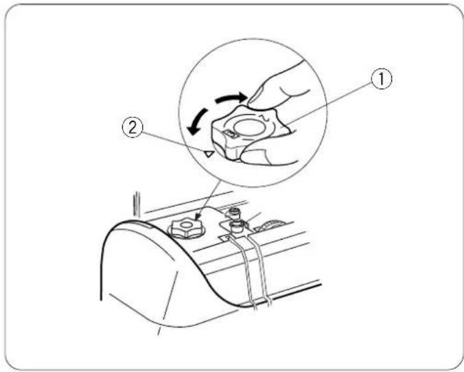
Align the foot pressure dial ① with the setting mark ② at "3" for regular sewing.
Reduce the pressure to "2" for appliqué, cutwork, drawn work, basting and embroidery.
Velours and knits with a lot of stretch may require a "1" setting.
text_image
Technical diagram of a sewing machine with labeled component and directional arrow indicating motionPresser Foot Lever and Additional Presser Foot Clearance
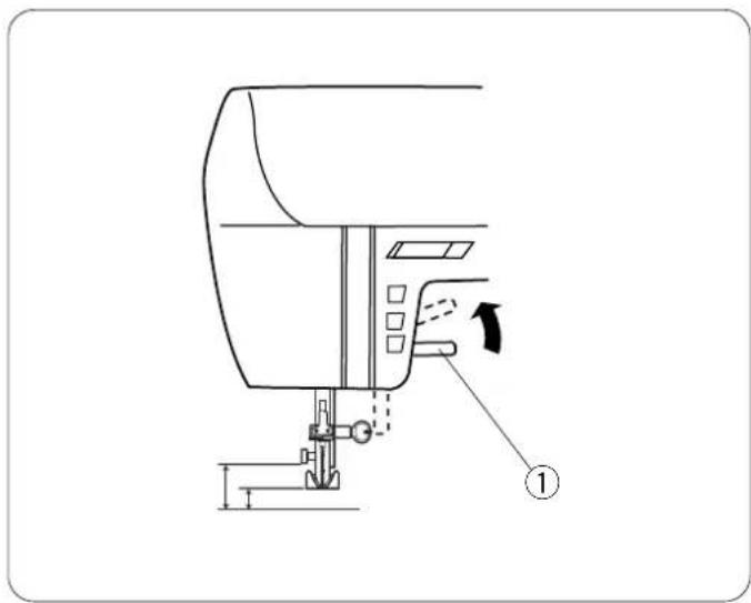
Before sewing can occur, the presser foot must be lowered to close the tension discs.
Raise and lower the foot with this lever ①.
You can raise the presser foot about 6.5 mm (1/4") higher than the normal up position for easy removal of the presser foot or to place heavy fabrics under the presser foot. Pull the presser foot lever up beyond the normal up position.
text_image
Diagram illustrating three-step sewing process for a shoe, showing step 1 to step 3 of the sewing machine's handle and base.Attaching and Removing Presser Feet
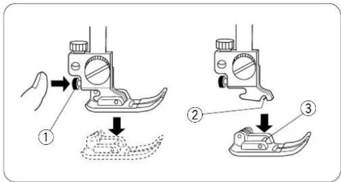
Press the "Up/Down Needle" key until the needle is in the raised position.
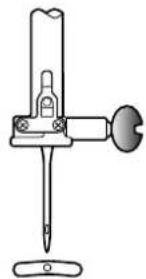
Turn OFF the power switch. Raise the presser foot and press the red button ① on back of the shank. The presser foot will drop off. Place the selected presser foot so the pin ③ on the foot lies just under the groove ② of the shank. Lower the presser bar and attach the foot.
text_image
Technical diagram showing three-step tool installation steps with labeled components and rotation arrowsAttaching and Removing Shank
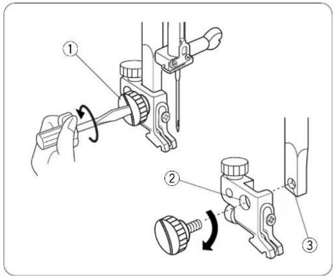
Turn OFF the power switch. Raise the presser bar. Turn the thumbscrew ① counterclockwise with the screwdriver to remove the shank.
To attach, match the hole in the shank ② with the hole in the presser bar ③. Put thumbscrew in hole and turn clockwise to tighten.
text_image
Technical diagram showing sewing machine stitching process with numbered steps and directional arrowSeam Allowance Lines
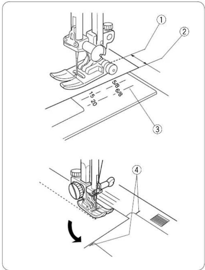
The lines on the needle plate, machine bed and bobbin cover plate help you measure seam width. The number indicates the distance between the center needle position (3.5) and the seam allowance line.
① Center needle position
② Edge of fabric
③ Guidelines
④ 90° pivot angle guideline for 5/8"
natural_image
Diagram showing two mechanical components with directional arrows indicating motion (no text or symbols)Controlling Sewing Speed
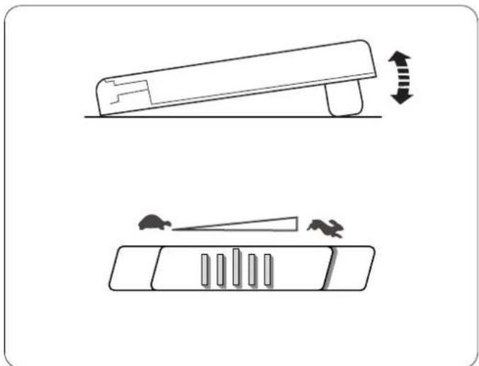
Sewing speed can be varied with the foot control. The harder you press on the foot control, the faster the machine runs.
The maximum sewing speed can be varied by sliding the speed control lever. For a faster speed, slide it to the right; for a slower speed, slide it to the left.
text_image
Diagram illustrating a sewing process with labeled parts including a spool, wire, and fabric swool.Adjusting the Needle Thread Tension
Choosing the Correct Tension — Straight Stitch
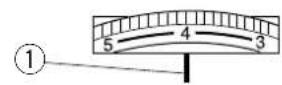
The ideal straight stitch will have threads locked between the two layers of fabric, as shown left (magnified to show detail). Needle thread tension can range from 3 – 5 and is normally set on 4. Align the 4 on the dial with the setting mark ①.
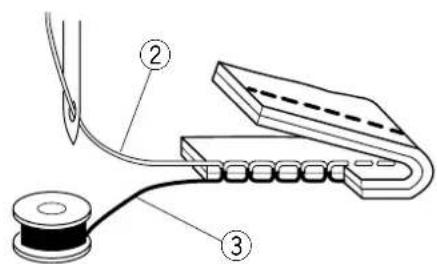
If you look at the needle thread ② (top thread) and bobbin thread ③ (bottom thread), you will notice that there are no gaps. Each stitch is smooth and even.
Occasionally the needle thread tension needs to be adjusted to a manual setting. Examples:
- s tiff or heavy fabric
- sewing more than two layers of fabric
- type of stitch
- thread
When adjusting needle thread tension, the higher numbers tighten, the lower numbers loosen.
text_image
Technical diagram showing four different types of clamping devices with labeled measurement scales (2, 3, 4, 5, 6) for scale reference.Tension is too tight
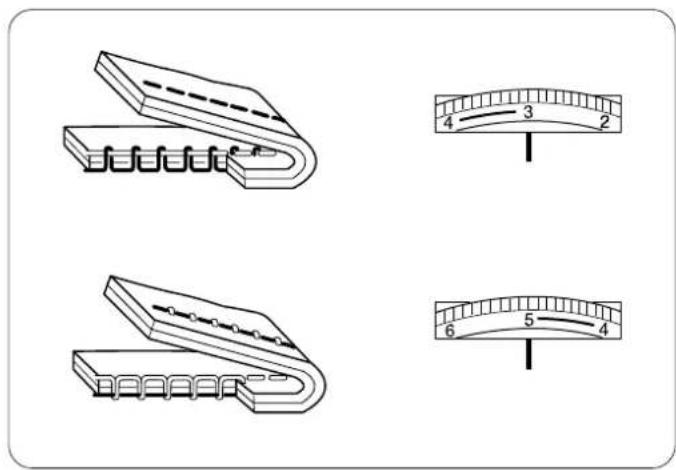
The bobbin thread shows through on the topside of the fabric and it will feel bumpy.
Turn the dial to a lower number to loosen the needle thread tension.
Tension is too loose
The needle thread shows through on the underside of the fabric and it will feel bumpy.
Turn the dial to a higher number to tighten the needle thread tension.
natural_image
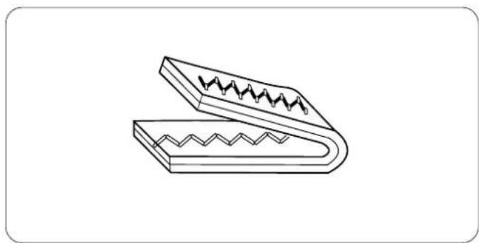
Line drawing of a mechanical clamp or spring-loaded component with zigzag grooves (no text or symbols)Adjusting Tension for Zigzag and Satin Stitches
The upper thread tension should be slightly looser when sewing a zigzag or a satin stitch. The upper thread should appear slightly on the underside of the fabric.
text_image
Diagram showing cable connection with labeled components including a switch, battery, and power outletSECTION II
Getting Ready to Sew
Connecting Machine To Power Supply
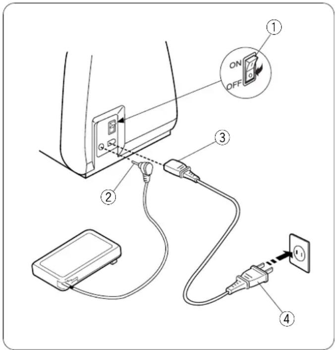
Before connecting the power cord, make sure the voltage and frequency shown on the machine are identical to your electrical power.
To connect machine to power supply, turn off the power switch ①. Insert the foot control plug ② and machine plug ③ into the machine and the power supply plug ④ into the wall socket.
Your machine may come equipped with a polarized plug (one prong wider than the other). A polarized plug reduces the risk of electrical shock. This plug is intended to fit into a polarized outlet. If the plug does not fit fully into the outlet, reverse the plug. If it still does not fit, contact a qualified electrician to install the proper outlet. Do not modify the plug in any way.
IMPORTANT: When using your sewing machine the first few times, place waste fabric under the presser foot and run the machine without thread for a few minutes. Wipe away excess oil.
NOTE: After turning off the machine, wait 5 seconds before turning it on again.
For Your Safety
Do not use extension cords or plug adapters.
Do not touch plug with wet hands.
Always turn off the power/light switch first and then unplug from the electrical outlet. Examples:
- when leaving the machine unattended
• w hen cleaning the machine
Always turn off the power/light switch:
- when attaching or removing parts such as needle, presser foot, needle plate
- when threading needle or bobbin
Do not place anything on the foot control.
Do not place heavy items on cords. Do not subject cords to heat. Do not use damaged cords. Have the cord repaired immediately.
While the machine is in operation, always keep your eye on the sewing area and do not touch any moving parts such as the thread take-up lever, flywheel or needle.
| Weight | Fabric Needle Type | Needle Size | |
| Very Chiffon, Fine Lace, Univergandy Ball Point 9 (65) | |||
| Light | Batiste, Lawn, Crepe de Chine, Challis, Handkerchief Linen, Crepe, Taffeta, Satin | Stretch 11 (75)Universal 11 (75) | 12 (80) |
| Single Knits, Jersey, Stretch Swimwear, Tricot Ball Point 11 (75) | |||
| Leather, Suede Leather | 11(75) | ||
| Medium | Flannel, Velour, Velvet, Velveteen, Corduroy, Linen, Gabardine, Wool, Terry, Burlap | Universal 14 (90) | |
| Double Knits, Stretch Velour, Stretch Terry, Sweater Knits | Ball Point 14 (90) | ||
| Leather, Vinyl, Suede | Leather | 14 (90) | |
| Heavy | Denim, Sailcloth, Ticking | Denim | 16 (100) |
| Coating, Polar Fleece, Drapery, and Upholstery Fabrics | Universal 16 (100) | ||
| Leather, Suede | Leather | 16 (100) | |
| Very Heavy | Canvas, Duck, Upholstery Fabrics | Universal 18 (110) | |
| Topstitching for Special Finish | Topstitching | 11 (75)14 (90) | |
text_image
Diagram showing a hand holding a tool with a labeled step and directional arrow indicating motion or direction.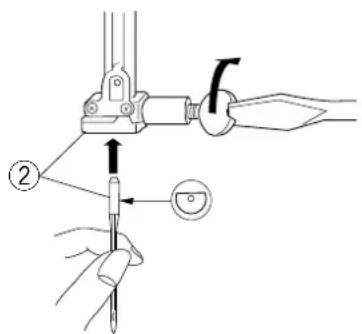
text_image
Technical diagram showing a tool being inserted into a mechanical component, labeled with step number 2 and directional arrow.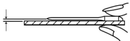
natural_image
Pure technical line drawing of a mechanical component with no text or symbolsSelecting the Correct Needle and Thread
There are many kinds of fabrics, threads and needles. It is important to use the correct ones together.
Always purchase good quality thread. It should be strong, smooth and even in thickness. Use the same thread for needle and bobbin. Always test thread and needle size on a scrap piece of fabric.
In general, fine threads (the larger the number, the finer the thread) and needles (the smaller the number, the finer the needle) are used for sewing lightweight fabrics and heavier threads and larger needles are used for sewing heavyweight fabrics. There are many specialty needles available from your sewing machine dealer.
Check your needles frequently for rough or blunt tips. Snags and runs in knits, fine silks and silk-like fabrics are permanent and are often caused by damaged needles.
NOTE: A universal needle size 14/90 comes inserted in your machine.
Changing Needles
-
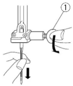
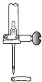
Turn ON the power switch. Press the "Up/Down Needle" key to raise the needle. Lower the presser foot. Turn OFF the power switch. Turn the needle clamp screw ① counterclockwise to loosen. Remove the needle from the clamp.
-
Insert the new needle into needle clamp with the flat side to the back, pushing it up as far as it will go ②. Tighten the clamp screw firmly.
-
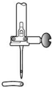
To determine if the needle is defective, place the flat side of the needle on something flat (a needle plate, piece of glass, etc.). The gap between the needle and the flat surface should be consistent.
Never use a bent or blunt needle, as it may cause skipped stitches or thread breakage. Defective needles can ruin the fabric. Always purchase good quality needles. Change needles often.
text_image
Labeled diagram of a laboratory pipette with six numbered parts for identificationNeedle Definitions
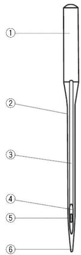
The illustration identifies the main parts of a sewing machine needle.
① Body
② Shaft
③ Long groove (round side of needle)
④ Short groove (flat side of needle)
⑤ Eye
⑥ Point
Universal – an all-purpose needle that handles most woven and knit fabrics.
Ball point – the point spreads the fibers, preventing tears and is especially suited for loose knits and interlock knits. Not recommended for embroidery.
Stretch – specially designed to prevent skipped stitches in synthetic suedes and elasticized knits (swimwear).
Denim – the sharp point effectively pierces densely woven fabrics such as denim and canvas.
Topstitching – the extra sharp point penetrates layers of fabrics; extra large eye and large groove accommodate heavyweight topstitching thread.
Metallic – the large grooved shaft helps prevent delicate metallic threads from shredding. Another plus, a larger than average eye makes for easier threading.
Self-Threading – the needle eye has a slit opening on the side to allow the thread to be easily inserted.
Leather – the cutting point creates small holes in leather and suede. Holes remain after stitching is removed.
Quilt – the tapered point easily penetrates through multiple layers and crossed seams.
Wing/Hemstitch – wide flat edges (wings) extend outwards near the eye; they separate fibers and create holes for beautiful heirloom stitches.
Twin/Double - 2 needles are joined on a crossbar and share a single shaft. Sews two parallel rows of stitching. Available in universal and ballpoint.
Keys and LED Readout
text_image
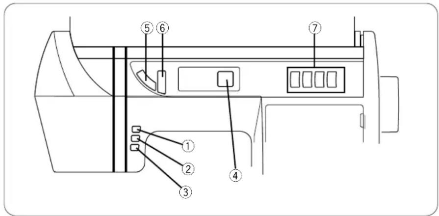
Technical diagram of a device rear panel with numbered components for identificationTurn ON the power switch. (Test lights run in LED readout.)
① Up/Down Needle Key
If the needle is up when you press this key, the needle will go down to its lowest position. The needle will continue to stop in the down position.
If the needle is down when you press this key, the needle will go up to its highest position. The needle will continue to stop in the up position.
② Auto-Lock Key
Press this key while sewing 01 (straight stitch), 02 (zigzag stitch) or 03 (3-step zigzag stitch) and the machine will sew a few stitches in place and stop automatically.
* Press this key while sewing utility or decorative stitches and the machine will complete the stitch, lockstitch and stop.
③ Reverse Key
If you are sewing 01 (straight stitch), 02 (zigzag stitch) or 03 (3-step zigzag stitch), press and hold this key. The machine will sew in reverse until you release the key.
* If you are sewing any other stitches, utility or decorative, the machine will immediately stop and sew a lockstitch when you press this key.
a
text_image
01-60 01 - + - + - - - -b
text_image
01-60 3.5©
text_image
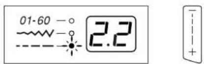
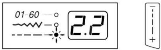
01-60 -○ ~○ 2.2 +④ Indicator Lights and LED Readout
① When this light is lit, the readout displays the selected stitch.
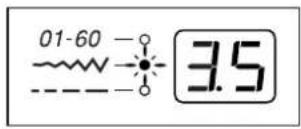
⑥ When this light is lit, the readout displays the selected stitch width/needle position.
© When this light is lit, the readout displays the selected stitch length.
text_image
01-60 - 3.5a
b
natural_image
Technical line drawing of a mechanical device with a pin and handle (no text or symbols)0.0
natural_image
Technical line drawing of a mechanical device with a pointed tip and base (no text or symbols)3.5
natural_image
Technical line drawing of a mechanical device with a rod and base, no text or symbols present7.0
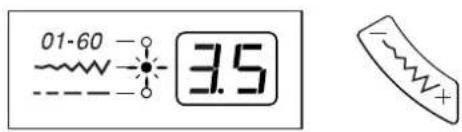
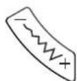
⑤ Stitch Width and Needle Position Key
Press this key to display pre-programmed stitch width or needle position.
To decrease stitch width or move needle position to the left, press “—” side of key.
To increase stitch width or move needle position to the right, press "+" side of key.
Stitches 01, 07 and 23 allow you to move from center needle position (3.5) to left (0.0) or right (7.0). There are 15 needle positions.
a Left position
b Center position
© Right position
text_image
01-60 —○ —○ —○ 2.2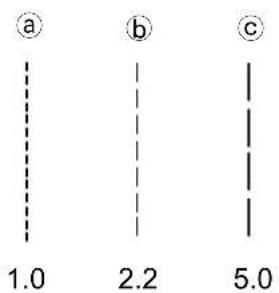
text_image
a b c 1.0 2.2 5.0⑥ Stitch Length Key
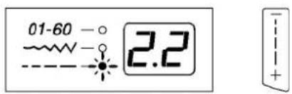
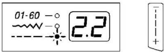
Press this key to display pre-programmed stitch length.
Depending on the stitch selected, stitch length can be set between 0.0 and 5.0.
To decrease length, press “—” side of key.
To increase stitch length, press "+" side of key.
a 1.0 Stitch length
b 2.2 Stitch length
© 5.0 Stitch length
NOTE: Fine fabrics should have a stitch length between 1.5 and 2.4, medium fabrics between 2.0 and 3.0 and heavier fabrics between 3.0 and 4.0.
text_image
01-60 01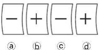
text_image
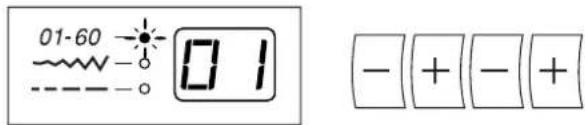
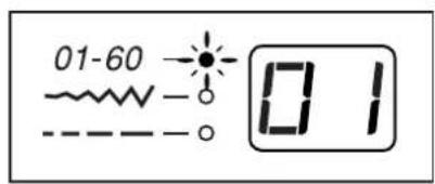
- + - + ① ② ③ ④⑦ Stitch Selection Keys
① Press this “-” key to change digit in the LED readout 10's column between 0 and 5.
Example: If the readout is 01 and this key is pressed, the readout will change to 51.
⑥ Press this “+” key to change digit in the LED readout 10's column between 0 and 5.
Example: If the readout is 01 and this key is pressed, the readout will change to 11.
© Press this “-” key to change digit in the LED readout 1's column between 0 and 9.
Example: If the readout is 01 and this key is pressed, the readout will change to 60.
(d) Press this “+” key to change digit in the LED readout 1's column between 0 and 9.
Example: If the readout is 01 and this key is pressed, the readout will change to 02.
text_image
Technical diagram showing sewing machine operation with labeled parts and directional arrows indicating steps 1, 2, and 3.Winding a Bobbin
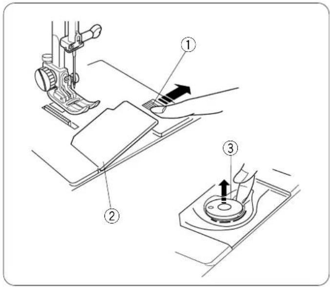
To remove bobbin, slide bobbin cover plate release button ① to the right and lift away the bobbin cover plate ②.
Lift out the bobbin ③.
Turn ON the power switch.
text_image
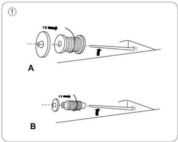
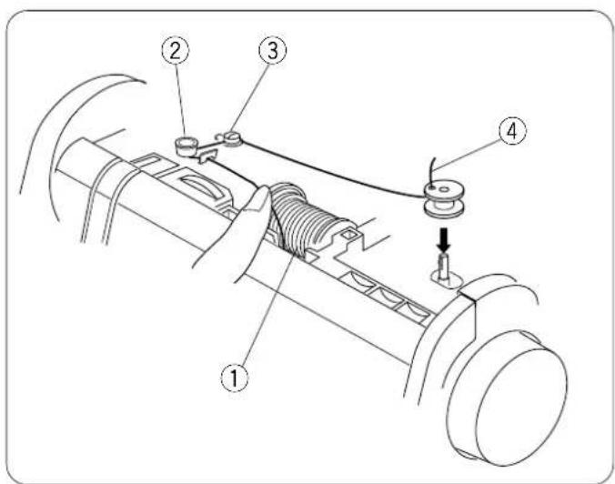
① A B① Lift up the spool pin. Place the spool of thread on the spool pin with the thread coming off the spool as shown. Attach the spool holder and press it firmly against the spool of thread.
NOTE: Spool holder needs to be changed according to the type of thread spool.
A. Large spool
B. Small spool
text_image
Technical diagram of a mechanical assembly with numbered components and a downward arrow indicating motion or force direction.② Pull the thread towards the thread guides, under the hook and wrap it around the guide as shown.
③ Pull the thread back around the bobbin winder thread guide.
④ Pass the thread through the hole in the bobbin from inside to the outside. Place the bobbin on the bobbin winder spindle.
⑤
natural_image
Pure mechanical diagram showing a pulley and lever mechanism without any text or symbols⑥
natural_image
Line drawing of a hand using scissors to cut a mechanical component (no text or symbols)⑦
natural_image
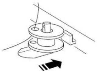
Diagram showing scissors cutting a spool with motion arrows indicating movement (no text or symbols)⑤ Push bobbin winder spindle to the right. The computer display screen will show a bobbin winding " ] [".
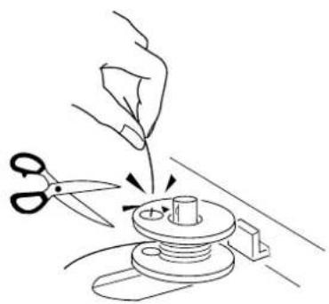
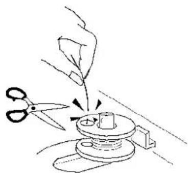
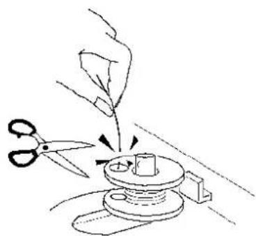
⑥ Holding the free end of the thread, press the foot control. Stop machine after the bobbin has made a few turns. Cut the thread tail close to the hole in the bobbin. Start machine again to continue winding bobbin. When the bobbin is fully wound, stop the machine.
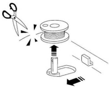
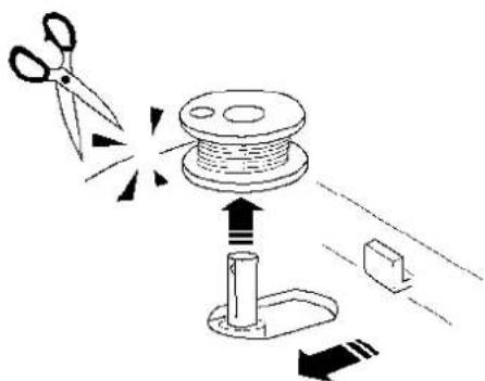
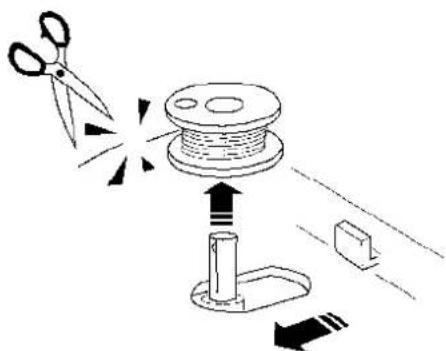
⑦ Move the spindle to the left to return the bobbin winder to its original position. Cut the thread as shown.
text_image
Technical diagram of a mechanical assembly with numbered components, showing a thread being inserted into a base.Additional Spool Pin
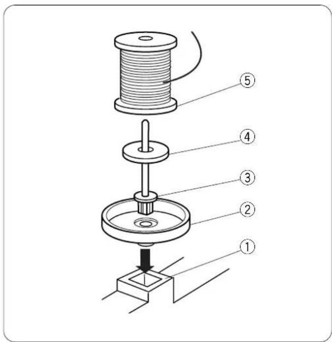
The additional spool pin can be used to wind an extra bobbin without unthreading the machine.
PROCEDURE: Insert the spool stand ② and the additional spool pin ③ in the hole ① (located to the right of the built-in spool pin). Place the felt ④ and spool ⑤ on the pin with the thread coming off the spool as shown.
natural_image
Mechanical assembly diagram showing a threaded component being inserted into a housing (no text or symbols)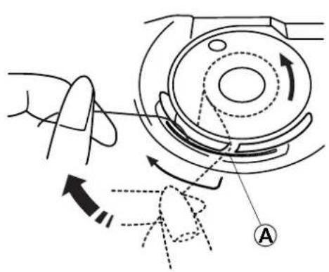
natural_image
Diagram of a mechanical device with directional arrows indicating motion, no text or symbols present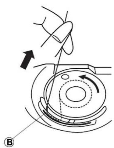
natural_image
Diagram of a hand operating a mechanical device with an arrow indicating direction (no text or symbols present)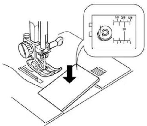
text_image
Diagram showing sewing machine operation with magnified view of measurement scale and needle gaugeInserting the Bobbin
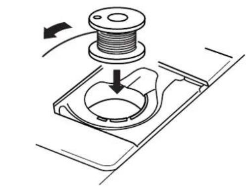
Place the bobbin in the bobbin case with the thread running counterclockwise.
Guide the thread into notch Ⓐ on the front side of the bobbin case.
Hold the bobbin with your right hand and pull the thread to the left, through the tension spring blades.
Continue pulling the thread lightly until the thread slips into notch Ⓑ.
Pull out about 15 cm (6") of thread.
Replace the bobbin cover plate.
Refer to the chart shown on the bobbin cover plate to check the threading.
text_image
Technical diagram of a sewing machine with numbered parts for identification and assembly reference.Threading the Machine
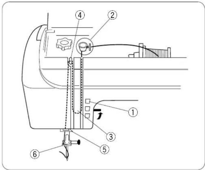
Raise the presser foot. Press the "Up/Down Needle" key ① until the needle is in an up position.
text_image
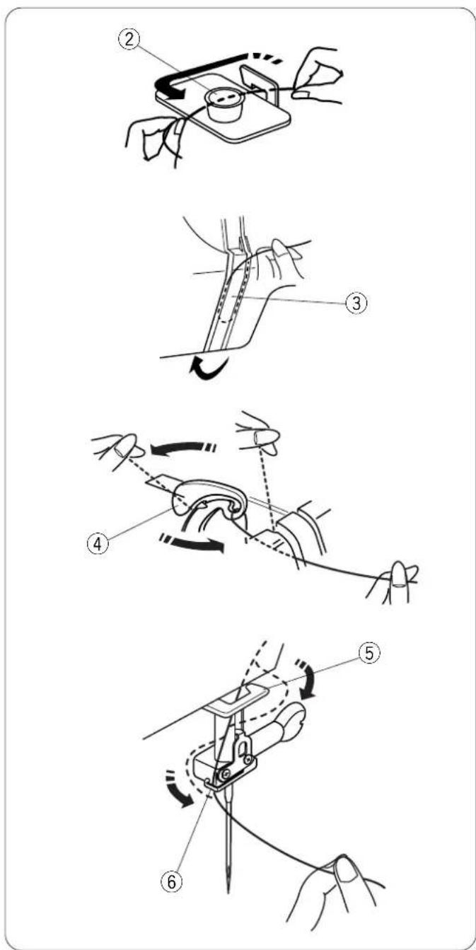
Technical diagram illustrating six steps of a sewing machine tool, labeled ② to ⑥, showing how to adjust the base and handle.Pull the thread under the hook and around upper thread guide ②.
Guide the thread down right channel and around the checkspring holder ③.
Pull the thread up left channel to the take-up lever. Firmly pull the thread from right to left, over the take-up lever and down into the take-up lever eye ④.
Proceed down left channel and through the lower thread guide ⑤.
Slide the thread to the left behind the needle bar thread guide ⑥.
Thread the needle from front to back manually or use the built-in needle threader.
Built-in Needle Threader
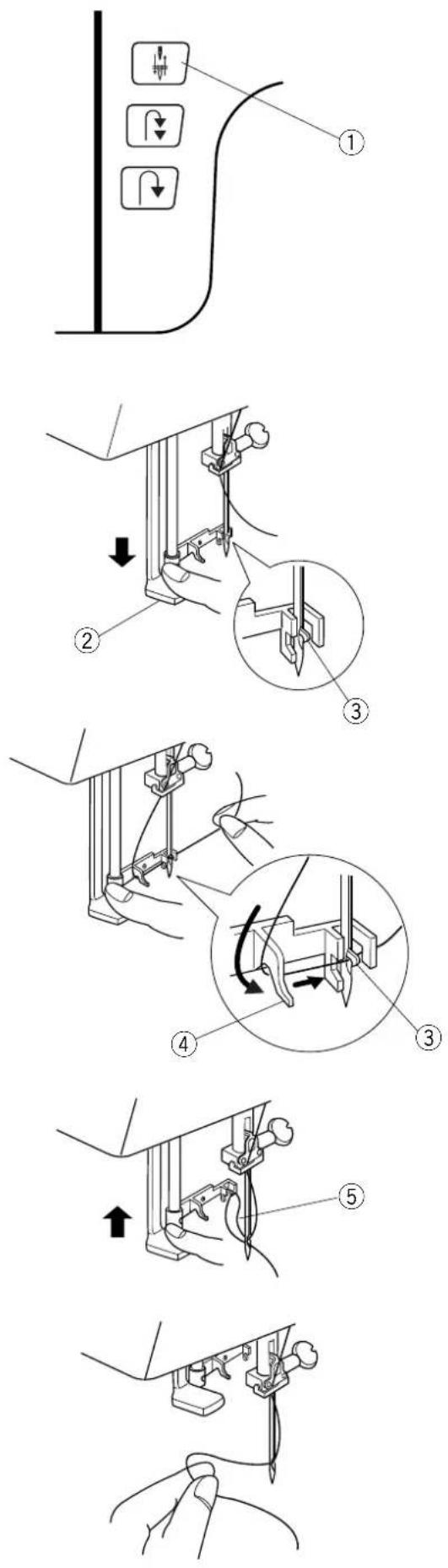
Press the "Up/Down Needle" key ① until the needle is in an up position. Turn OFF the power switch. Lower the presser foot.
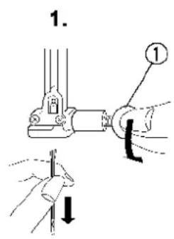
Lower the needle threader lever ② as far as it will go. Hook ③ is automatically inserted into the needle eye.
Bring the thread around guide ④ and under hook ③.
Slowly release the lever while holding the thread end and let the needle threader return to its original position. A loop of thread ⑤ is pulled through the needle eye.
Pull the thread loop off the guide to the back and manually bring the thread through the needle eye.
- The needle threader can be used with #11 to #16 size needles. Thread weight may vary from 30 to 100.
NOTE: Needle threader cannot be used with a twin needle or wing needle.
If the needle threader does not catch a thread loop, check the needle and positioning.
text_image
Technical diagram illustrating three-step sewing process for fabric, showing steps from sewing machine to final sewing.Drawing Up the Bobbin Thread
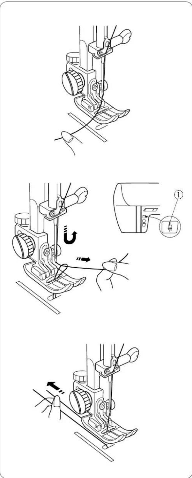
Turn ON the power switch. Raise the presser foot and hold the needle thread lightly with your left hand.
Press the "Up/Down Needle" key ① twice to pick up the bobbin thread.
Draw up the needle thread together with a loop of bobbin thread.
Slide 10 cm (4") of both threads to the back under the presser foot.


Buttonhole Variations
All buttonholes should use interfacing that is the same weight as the fabric. Interfacing is especially important when sewing on stretch fabrics.
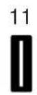
11 Classic Buttonhole
The most common buttonhole, found on blouses, shirts, pants, etc. It consists of a bartack at each end and a compact zigzag stitch along each side.
12 Classic Keyhole Buttonhole
Accommodates the shank found on large buttons used on heavy coats and jackets.
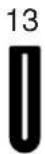
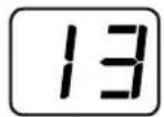
13 Jeans Buttonhole
Traditionally found on ready to wear jeans and other denim garments.
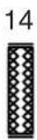
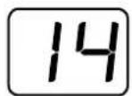
14 Stretch Buttonhole
Designed for non-woven fabrics such as knit and jersey. It provides a decorative touch
Test sew the buttonhole on a sample swatch of the same fabric. Include the interfacing and any seam allowances that will be in the actual garment. This is very important to ensure the buttonhole style and fabric are compatible.
text_image
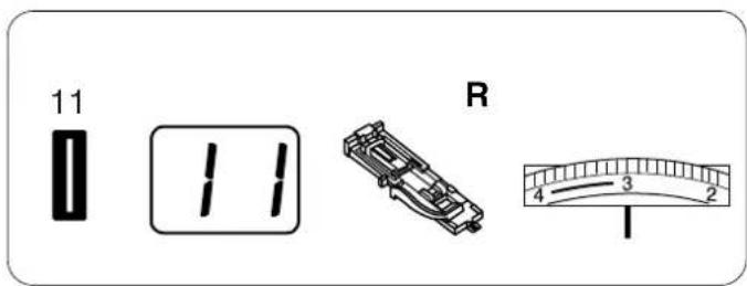
11 11 R 4 3 2 ISelect a buttonhole style - 11 through 14.
Alter the buttonhole width to match the fabric and thread.

natural_image
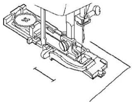
Technical line drawing of a mechanical assembly with labeled component (no text or symbols present)Attach buttonhole foot (R) with the buttonholder ① to the rear.
text_image
Technical diagram showing mechanical assembly with labeled components and directional arrows indicating motion or force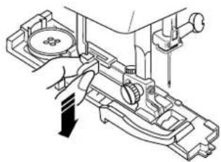
natural_image
Technical line drawing of a mechanical assembly with no visible text or symbols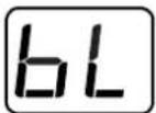
natural_image
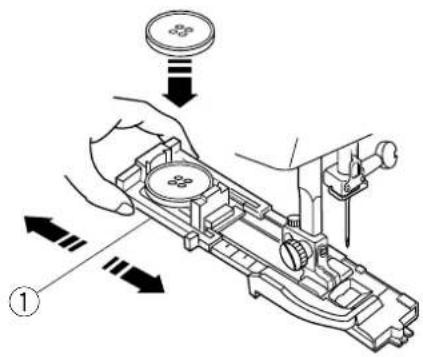
Technical line drawing of a sewing machine mechanism (no text or symbols)Pull open the buttonholder ① to the back and place the button in it. Push the holder together tightly around the button.
Placing the button in the automatic buttonhole foot (R) automatically sets the size of the buttonhole. The buttonholder adjusts for buttons with a diameter between 0.5 cm (3/16") and 2.5 cm (1").
Pull the buttonhole lever down as far as it will go.
NOTE: The machine stops sewing and shows warning message "bL" if the buttonhole lever is not lowered when sewing buttonholes. Pull down the buttonhole lever and start sewing.
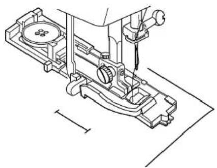
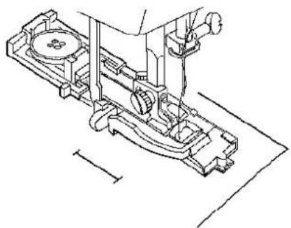
Mark the buttonhole area on the fabric. Place both threads to the left under the foot. Insert the garment under the foot and hand turn the flywheel to lower the needle at the starting point. Then lower the buttonhole foot.
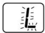
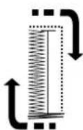
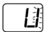
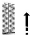
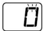
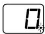
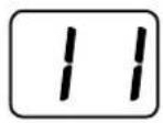
While sewing the buttonhole, the LED readout flashes which portion is currently being sewn.
A flashing “.” in the LED readout signals that the buttonhole is finished. Raise the presser foot and the “.” disappears.
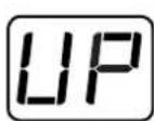
NOTE: If presser foot is not raised and another stitch is selected, the warning message "UP" will appear.
①
natural_image
Diagram of a hand inserting a card into a device (no text or symbols visible)②
text_image
Diagram showing a brush applying material to a cylindrical object, labeled with number ②③
natural_image
Diagram of a device with arrows indicating internal components (no text or symbols)SECTION III
Taking Care of Your Machine
Your machine has been meticulously designed and manufactured to give you a lifetime of sewing pleasure. not store the machine in a high humidity area, near a radiator or in direct sunlight. The machine is selflubricator however, the area around the bobbin and hook must be cleaned each time the machine has had extensive use. not dismantle the machine further than explained on these pages. Clean the outside of the machine with a soft cloth and pure soap.
Cleaning the Bobbin Area
Loose threads and dust may cause puckered stitches and thread breakage during stitching. Check for lint buildup after each project is completed.
Press the "Up/Down Needle" key until the needle is raised. Turn off power switch. Unplug the machine before cleaning.
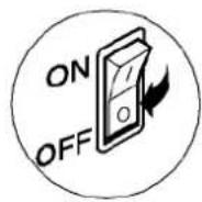
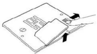
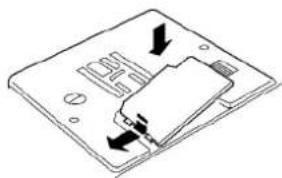
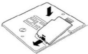
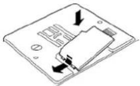
① Slide the bobbin cover plate release button to the right to remove the bobbin cover plate.
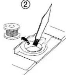
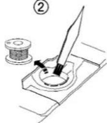
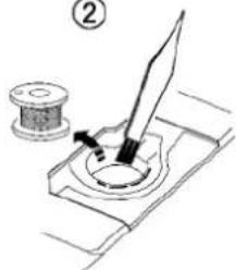
② Take out the bobbin; brush out dust and lint. (You can also use a small vacuum cleaner.)
③ Insert the bobbin and attach the bobbin cover plate.
①
natural_image
Technical line drawing of a mechanical assembly with a tool inserted into a component (no text or symbols)②
natural_image
Line drawing of a hand pressing down on a device panel (no text or symbols visible)Cleaning the Hook Area and Feed Dog
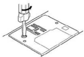
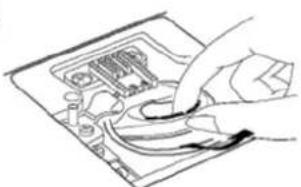
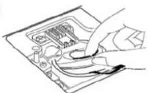
① Remove the presser foot, bobbin cover plate, needle and bobbin. Use the screwdriver supplied with the machine to remove the screw on the left side of nee plate.
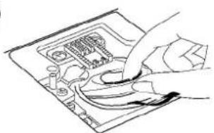
② Remove the needle plate. Lift up and remove the bobbin case.
text_image
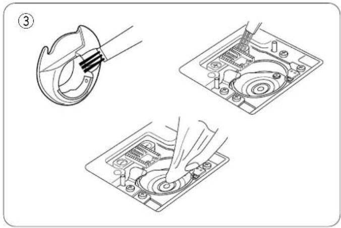
Technical diagram showing three steps of a sewing machine operation: hook insertion, back turned, and base cutting.③ Clean the feed dog and hook area with the lint brush. Wipe out gently with soft, dry cloth. (You can also use a small vacuum cleaner.)
text_image
Technical diagram showing three steps of a device operation: adding a switch, adding a component to a battery pack, and using a screwdriver.Replacing the Bobbin Case
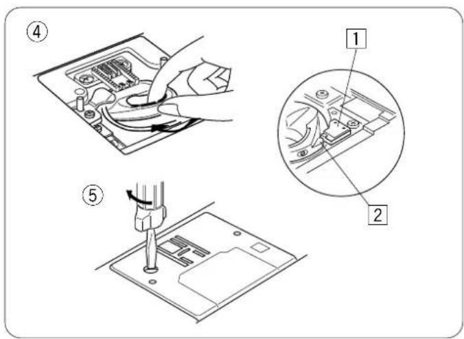
④ Insert the bobbin case so the knob fits next to the stopper in the hook area.
1 Stopper
2 Knob
⑤ Replace the needle plate, inserting the two needle plate guide pins into the holes in the needle plate. Replace the screw.
After cleaning, be sure to replace the needle, presser foot and bobbin.
text_image
Technical diagram showing a mechanical assembly with labeled parts and directional arrows indicating motion or assembly steps.Changing the Light Bulb
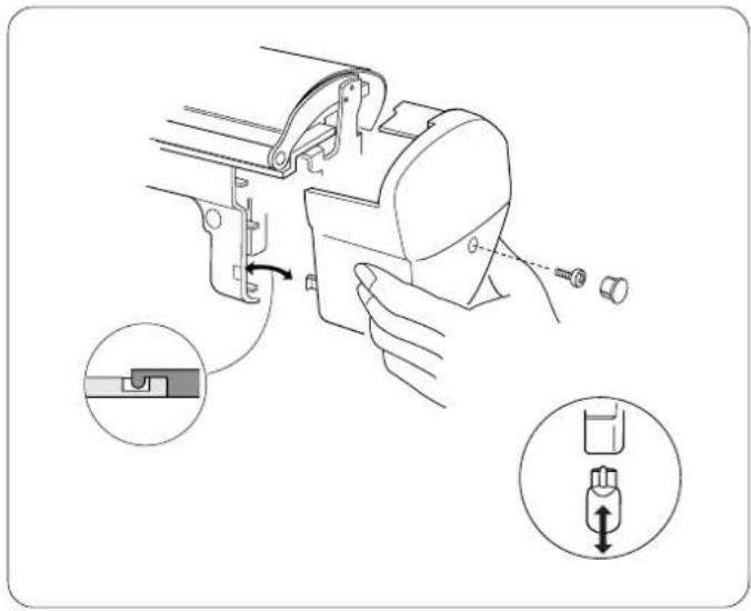
The sewing light is located behind the face plate. Unplug the machine. Remove screw cap and screw. Pull away face plate.
Pull out light socket. Pull out light bulb. Push in light bulb with pins aligned to holes in light socket. Push in light socket.
Replace face plate, screw and screw cap.
NOTE: Only use same type light bulb rated 12 Volts, 5 watts.
Stitch Chart
| 01 | 02 | 03 | 04 | 05 | 06 | 07 | 08 | 09 | 10 |
| 3 | 1 | ||||||||
| 11 | 12 | 13 | 14 | 15 | 16 | 17 | 18 | 19 | 20 |
| SEN | |||||||||
| 21 | 22 | 23 | 24 | 25 | 26 | 27 | 28 | 29 | 30 |
| 31 | 32 | 33 | 34 | 35 | 36 | 37 | 38 | 39 | 40 |
| 41 | 42 | 43 | 44 | 45 | 46 | 47 | 48 | 49 | 50 |
| 51 | 52 | 53 | 54 | 55 | 56 | 57 | 58 | 59 | 60 |
Optional Accessories
Elna is pleased to offer the following optional accessories for your machine. This listing is current at time of printing, but we are always developing new accessories to make sewing easier. Contact your authorized Elna dealer or service center to learn more about the latest innovations OR visit us at our website: www.elna.com.
| Part Number | Accessory Name | Part Number | Accessory Name |
| 495100-20 | Open Toe Satin Stitch Foot | 395719-26 | Walking Foot |
| 495470-20 | Appliqué Foot | 395719-90 | Walking Foot w/Quilt Guide |
| 495480-20 | Piping Foot | 395719-22 | Quarter Inch Foot |
| 495851-20 | Fringe/Looping Foot | 395741-96 | Scant Quarter Inch Foot |
| 495320-20 | Pintuck Foot, Narrow | 395719-28 | Ruffler |
| 395719-16 | Cord Guide, Narrow | 395719-12 | Gathering Foot |
| 495400-20 | Pintuck Foot, Wide | 395719-11 | Bias Binder Foot |
| 395719-17 | Cord Guide, Wide | 395719-33 | Hemmer Foot, 2 mm |
| 495265-20 | Pearl/Bead Foot 2 mm | 395719-20 | Straight Stitch Foot |
| 495260-20 | Pearl/Bead Foot 4 mm | 395719-19 | Roller Foot |
| 495560-20 | Fagoting Plate, Narrow | 395719-21 | Teflon® Foot |
| 495330-20 | Fagoting Plate, Wide | 495010-20 | Zipper Foot, Invisible |
| 495390-20 | Elastic Gatherer w/Plate, 8.0 mm | 395719-78 | Button Sewing Foot |
| 495845-20 | Elastic Gatherer w/Plate, 10 mm | 424630-10 | Rug Making Fork |
| 495525-20 | Elastic Gatherer w/Plate, 13 mm | 395721-56 | Circular Sewing Device |
| 495860-20 | Ribbon/Sequin Foot | 395719-51 | Seam Guide |
| 495050-20 | Embroidery/Darning Foot | 395731-94 | Straight Stitch Needle Plate |
TROUBLESHOOTING
| Condition Cause | See page(s) | |
| Needle thread breaks | 1. The needle is not threaded properly.2. The needle thread tension is too tight.3. The needle is bent or blunt. 124. The needle is not inserted correctly. 125. The thread is either too heavy or too fine for the needle. 126. The thread is tangled around spool. 20 | 2010 |
| Bobbin thread breaks | 1. The bobbin thread is not threaded correctly in the bobbin case.2. Lint has collected in the bobbin case.3. The bobbin is damaged and does not turn smoothly. | 1925-26Change bobbin. |
| Needle breaks | 1. The needle is not inserted correctly.2. The needle is bent or blunt.3. The needle clamp screw is loose.4. The needle thread tension is too tight.5. The needle is too fine for the fabric being sewn. | 1212121012-13 |
| Skipped stitches | 1. The needle is not inserted correctly.2. The needle is bent or blunt.3. The needle and/or the thread are not suitable for the fabric being sewn.4. A stretch needle is not being used for sewing stretch, very fine and synthetic fabrics.5. The needle thread is not threaded properly.6. The foot pressure dial is not adjusted correctly.7. The wrong needle is being used. | 121212-1312-1320812-13 |
| Seam puckering | 1. The needle thread tension is too tight.2. The machine is not threaded correctly.3. The needle is too large for the fabric being sewn.4. The stitch length is too long for the fabric.5. The foot pressure dial is not adjusted correctly.Place light weight stabilizer under lightweight fabrics. | 1019-2012168 |
| Slipping fabric | 1. The foot pressure dial is not adjusted correctly. | 8 |
| Fabric does not feed smoothly | 1. The feed dog is packed with lint.2. The foot pressure dial is not adjusted correctly.3. The stitches are too short.4. The feed dog was not raised after being lowered. | 25-268167 |
| Gathering | 1. The needle thread tension is too tight.2. The needle is either too large or too small for the thread.3. The stitches are too long for fabric weight. | 101216 |
| Machine does not work | 1. The machine is not plugged in.2. A thread is caught in the hook area.3. The bobbin winder spindle is still in the winding position. | 1125-2618 |
| Stitches are distorted | 1. The fine adjustment screw is not adjusted properly.2. The needle thread tension is too tight.3. The stitch length is not suitable for the fabric being sewn.4. Use interfacing for fine or stretch fabrics. | 71016Use stabilizer. |
| Buttonholes do not work | 1. Interfacing is not being used with fabrics.2. Buttonhole lever is not pulled down. | 2324 |
| Noisy operation | 1. Threads have been caught in the hook area.2. Lint has built up in the bobbin case or hook area. | 25-2625-26 |
| Fabric layers shift | 1. The foot pressure dial is not adjusted correctly. | 8 |
| Machine stops and Lo appears | 1. Threads have been caught in the hook area.2. Lint has built up in the bobbin case or hook area.3. The machine is not threaded correctly.4. The fabric is too heavy. | 25-2625-2619-2012 |
| Machine stops and E1 appears | 1. Machine needs servicing. | Contact your authorized Eina service center. |
You may hear a faint humming sound coming from your machine's internal motors. This is normal and no cause for concern.
INDEX
A
Accessories 4, 5-6, 28
Accessory Storage 3,4
Auto-Lock Key 14
B
Bobbin
Drawing Up Bobbin Thread 22
Inserting 19
Winding 17-18
Bobbin Case 19, 25
Buttonhole Variations....23-24
C
Centimeter Measurements 9
Circular Sewing Pivot Pin 6,7
Cleaning 25-26
Connecting Machine to Power Supply .....11
F
Fabric 12,16
Face Plate 3,26
Feed Dog 7
Fine Adjustment Screw 7
Flywheel 3
Foot Control 5,9
Foot Pressure Dial 3,8
FreeArm 3,6
Function Keys 14-16
|
Inch Measurements 9
Indicator Lights....15
L
LED Readout 3, 15
Light Bulb 3,26
Lockstitch 14
M
Maintenance 25-26
N
Needle Plate 3, 9, 25
Needle Position 15
Needle Threader 3
Needles 12-13
0
Optional Accessories....28
P
Part Names 3
Plugs 3,11
Power/Light Switch 3,11
Presser Feet
Attaching and Removing....8
Clearance 8
Definitions 5-6
Presser Foot Lever 3,8
R
Reverse Key 3, 14
S
Seam Allowance Lines....9
Shank 3,9
Speed Control....3, 9
Spool Pins 3, 4, 17, 18
Stitch Chart....3, 27
Stitch Length Key 3, 16
Stitch Selection Keys 3, 16
Stitch Width Key....3, 15
T
Thread 12
Thread Tension 10
Threading 20
U
Up/Down Needle Key 3, 14
W
Wing Needle 13
Mode d'emploi
eXperience 620
natural_image
Line drawing of a sewing machine labeled '620' with 'eXperience 620' branding, no additional text or symbols present.INSTRUCTIONS DE SÉCURITÉ IMPORTANTES
text_image
Technical diagram of a sewing machine with numbered parts and close-ups of the internal components.SECTION I
text_image
Technical diagram of a mechanical assembly with labeled components including parts 1, 2, 3, and 4.Accessoires standard
Volet supérieu
natural_image
Line drawing of a hand inserting a device into a container (no text or symbols)natural_image
Line drawing of a bag with 'elna' branding and handle (no additional text or symbols)25
natural_image
Line drawing of a mechanical bracket or housing component (no text or symbols)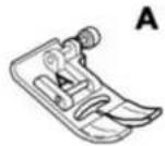
natural_image
Technical line drawing of a mechanical component with no visible text or symbols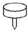
natural_image
Line drawing of a sewing machine with hands operating the component (no text or symbols)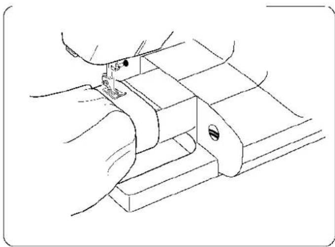
natural_image
Line drawing of a hand using a sewing machine to adjust or install a mechanical component (no text or symbols present)G: Pied ourlet invisible
natural_image
Line drawing of a car interior with a numbered component (1) pointing to the top section, no text or symbols present.text_image
Diagram illustrating the process of a device with labeled components and corresponding schematic diagrams showing polarity changes.text_image
Diagram showing a sewing machine's step-by-step instructions for inserting a small object, labeled with numbers ① and ②.Abaisser la griffe de transport
text_image
Technical diagram showing a hand operating a mechanical component with labeled parts ① and ②, including directional arrows indicating motion.Pression du pied
text_image
Technical diagram of a sewing machine with labeled parts and measurement indicatorstext_image
Diagram showing a sewing machine needle insertion process with labeled parts and directional arrows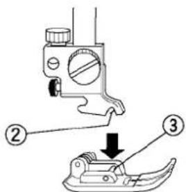
text_image
Diagram showing a sewing machine with labeled parts and a downward arrow indicating a sewing process step.text_image
Technical diagram showing three-step mechanical assembly steps with labeled components and directional arrows indicating motion.text_image
Technical diagram showing sewing machine stitching process with numbered steps and directional arrownatural_image
Diagram showing two different motion scenarios: one with an inclined ramp and the other with a triangular ramp, both with directional arrows indicating motion direction (no text or symbols present)text_image
Technical diagram showing cable connection with labeled parts: wire, cable, and wire spool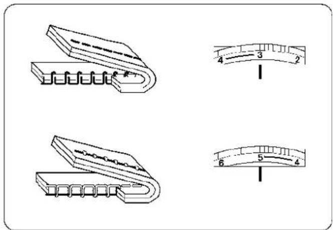
text_image
Technical diagram showing four different types of clamping or fastening components with labeled parts and a scale bar.text_image
Diagram showing cable connection to a device with labeled components and an ON/OFF switch indicatorSECTION II
text_image
Diagram of a laboratory pipette with six labeled parts, showing internal structure and tip alignment.text_image
Technical diagram of a device rear panel with numbered components and labeled partstext_image
01-60 3.5 a b c 0.0 3.5 7.0text_image
Technical diagram of sewing machine components with numbered parts and directional arrows indicating assembly stepsRemplir la canette
text_image
Technical diagram of a mechanical assembly with numbered components and a downward arrow indicating motion or force direction.natural_image
Technical line drawing of a mechanical component with an arrow indicating direction (no text or symbols)⑥
natural_image
Illustration of a hand using scissors to cut a small object on a base, with no text or symbols present.⑦
natural_image
Diagram showing scissors cutting a spool with an arrow indicating direction (no text or symbols)text_image
Technical diagram of a mechanical assembly with numbered components, showing a thread being inserted into a base.text_image
Technical diagram of a sewing machine with numbered components and structural detailsEnfilage de la machine
text_image
Technical diagram illustrating six steps of a mechanical or electrical procedure with numbered annotations.natural_image
Technical line drawing of a mechanical assembly with labeled component (1), no readable text or symbols presenttext_image
Technical diagram showing mechanical assembly with labeled components and directional arrows indicating motion or force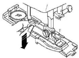
natural_image
Mechanical assembly diagram showing a hand operating a valve with a circular component and shaft (no text or labels)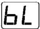
natural_image
Technical line drawing of a mechanical assembly with no visible text or symbolsnatural_image
Line drawing of a hand inserting a card into a folder (no text or symbols)②
text_image
Diagram showing a tool interacting with a mechanical component, labeled with number ②③
natural_image
Diagram of a device with arrows indicating movement or force, no text or symbols presentSECTIONIII
Entretien de la machine
natural_image
Line drawing of a mechanical component with a tool inserted, showing internal structure (no text or symbols)②
natural_image
Line drawing of a hand inserting a cable into a device (no text or symbols)text_image
Technical diagram showing three steps of a mechanical or electronic device operation, with labeled components and hand tool.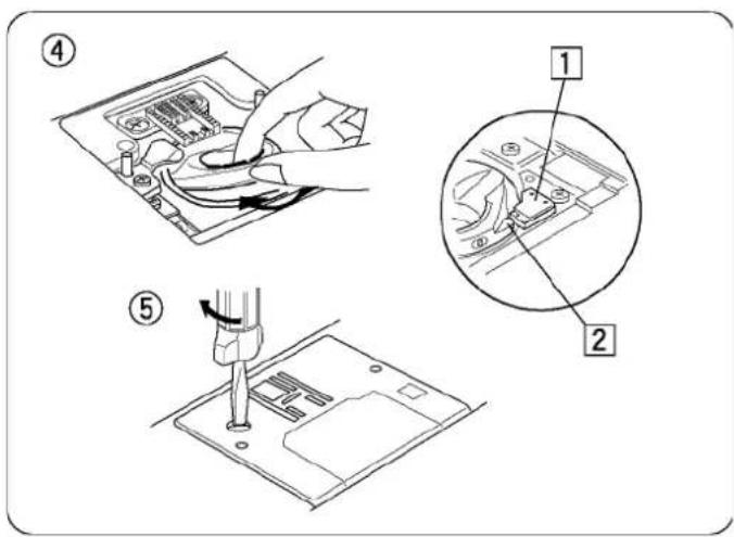
text_image
Technical diagram showing three steps of a device operation: adding cable, inserting into a socket, and using a tool to adjust the socket.
text_image
Technical diagram showing mechanical assembly steps with magnified insets highlighting component detailsnatural_image
Line drawing of a sewing machine with '620' branding and 'eXperience 620' label, no additional text or symbols present.text_image
Technical diagram of a sewing machine with numbered parts and exploded view, including close-ups and internal components.ABSCHNITT I
text_image
Technical diagram of a mechanical assembly with labeled components including parts 1, 2, 3, and 4.natural_image
Line drawing of a hand holding a device with a scroll wheel (no text or symbols)natural_image
Pure technical line drawing of a mechanical part or bracket (no text or symbols)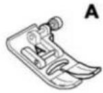
natural_image
Technical line drawing of a mechanical component with no visible text or symbols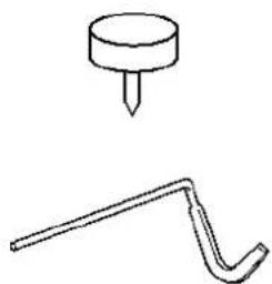
natural_image
Simple line drawing of a pin and a curved tool (no text or symbols)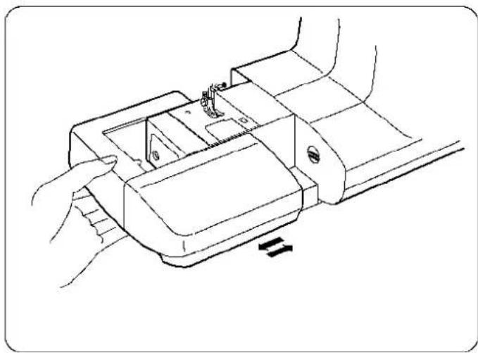
natural_image
Line drawing of a sewing machine with hands operating the component (no text or symbols)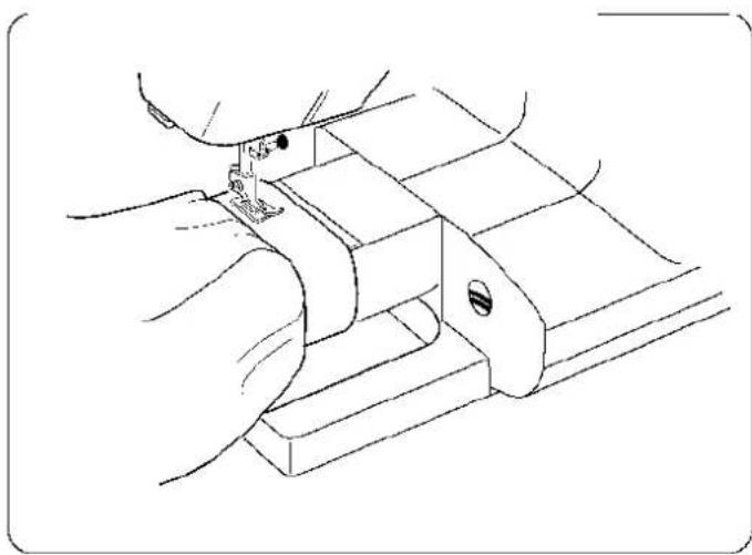
natural_image
Line drawing of a hand using a sewing machine to adjust or install a mechanical component (no text or symbols present)G: Blindsaum-Fuss
text_image
Technical diagram of a car intake manifold with labeled component ①text_image
Diagram illustrating a cable connector assembly with labeled parts and polarity indicatorstext_image
Technical diagram showing a sewing machine operation with labeled parts ① and ②, including a sewing machine needle.text_image
Technical diagram showing a hand holding a mechanical component with labeled parts and directional arrows indicating motion or assembly.text_image
Technical diagram of a sewing machine with labeled parts and measurement indicatorstext_image
Diagram showing a sewing machine needle stitching fabric, with labeled parts and directional arrows indicating process flow.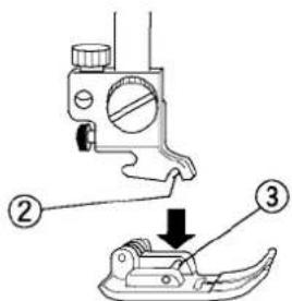
text_image
Diagram showing a sewing machine with labeled parts and a downward arrow indicating a sewing process step.text_image
Technical diagram showing three-step mechanical assembly steps with numbered annotationstext_image
Technical diagram showing sewing machine stitching process with numbered steps and rotation indicatornatural_image
Diagram showing two types of motion: a ramp and a vehicle with a triangular ramp, both with directional arrows indicating motion (no text or symbols)text_image
Diagram showing a sewing machine with labeled parts including a spool, cable, and connectortext_image
Technical diagram showing four different types of electrical connectors with labeled measurement scales (2, 3, 4, 5, 6) for scale reference.Zu grosse Spannung
natural_image
Line drawing of a mechanical clamp or clip with zigzag grooves and spring-like teeth (no text or symbols)text_image
Diagram showing cable connection to a device with labeled components and an ON/OFF switch indicatorABSCHNITT II
| Weight | Fabric Needle Type Needle | Size | |
| Very Light | Chiffon, Fine Lace, Organdy Ball Point 9 | Universal 9 (65) (65) | |
| Light | Batiste, Lawn, Crepe de Chine, Challis, Handkerchief Linen, Crepe, Taffeta, Satin | Stretch 11 (75) Universal 11 (75) 12 (80) | |
| Single Knits, Jersey, Swimwear, Tricot | Stretch 11 Ball Point (75) 11 (75) | ||
| Leather, Suede | Leather | 11(75) | |
| Medium | Flannel, Velour, Velvet Velveteen, Corduroy, Linen, Gabardine, Wool, Terry, Burlap | Universal 14 (90) | |
| Double Knits, Stretch Velour, Stretch Terry, Sweater Knits | Ball Point 14 (90) | ||
| Leather, Vinyl, Suede | Leather | 14 (90) | |
| Heavy | Denim, Sailcloth, Ticking | Denim | 16 (100) |
| Coating, Polar Fleece Drapery, and Upholstery Fabrics | Universal 16 (100) | ||
| Leather, Suede | Leather | 16 (100) | |
| Very Heavy | Canvas, Duck, Upholstery Fabrics | Universal 18 (110) | |
| Topstitching for Special Finish | Topstitching | 11 (75) 14 (90) |
text_image
1. ①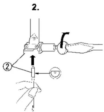
text_image
2. ②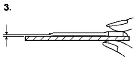
text_image
3.text_image
Diagram of a pen-like tool with six labeled parts, showing structural details and tip geometry.text_image
Technical diagram of a device rear panel with numbered components and labeled partstext_image
01-60 3.5©
text_image
01-60 -○ ~○ 2.2 +text_image
01-60 3.5 a b c 0.0 3.5 7.0(a) Linke Position
(b) Mittlere Position
(c) Rechte Position
text_image
01-60 -○ ~○ 2.2 +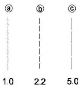
text_image
a b c 1.0 2.2 5.0⑥ Stichlängen-Taste
text_image
Technical diagram of sewing machine components with numbered parts and directional arrows indicating assembly stepsAufspulen
text_image
Technical diagram showing two mechanical assembly steps labeled A and B, with directional arrows indicating motion or movement.text_image
Technical diagram of a mechanical assembly with numbered components and a downward arrow indicating motion or force direction.natural_image
Technical line drawing of a mechanical component with an arrow indicating direction (no text or symbols)⑥
natural_image
Line drawing of a hand using scissors to cut a small object on a base, with no text or symbols present.⑦
natural_image
Diagram showing scissors cutting a spool with an arrow indicating direction (no text or symbols)text_image
Technical diagram of a mechanical assembly with numbered components, showing a thread being inserted into a base.natural_image
Mechanical diagram showing a threaded component being inserted into a housing, with an arrow indicating the process (no text or symbols present)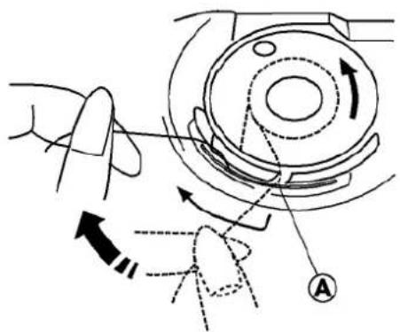
text_image
Technical diagram showing mechanical assembly with labeled components and directional arrows indicating motion or movement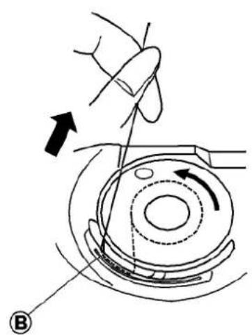
natural_image
Diagram of a hand operating a mechanical component with an arrow indicating direction (no text or symbols present)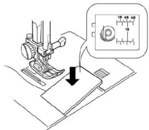
text_image
Diagram showing sewing machine stitching a fabric with measurement scale and magnified view of the needle gaugeSpule einsetzen
text_image
Technical diagram of a sewing machine with numbered components and structural detailstext_image
Technical diagram illustrating six steps of a mechanical or electrical procedure with numbered annotations.text_image
11 11 R 4 3 2 I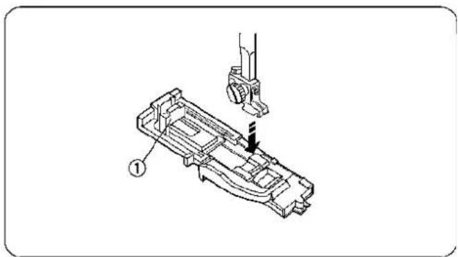
natural_image
Technical line drawing of a mechanical assembly with a tool and component, no visible text or symbolstext_image
Technical diagram showing mechanical assembly with labeled components and directional arrows indicating motion or force
natural_image
Mechanical assembly diagram showing a hand operating a valve with a circular component (no text or labels)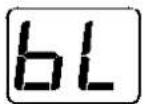
natural_image
Technical line drawing of a sewing machine mechanism (no text or symbols)natural_image
Diagram of a device being inserted into a folder, showing arrows indicating direction (no text or symbols)②
text_image
Diagram showing a brush tip interacting with a spool, labeled with number ②③
natural_image
Diagram of a device with arrows indicating movement or force, no text or symbols presentnatural_image
Technical line drawing of a mechanical assembly with a tool inserted into a component (no text or symbols)②
natural_image
Line drawing of a hand inserting a plug into an electronic device (no text or symbols visible)text_image
Technical diagram showing three steps of a mechanical device operation: tool insertion, assembly, and disassembly.text_image
Technical diagram showing three steps of a device operation: adding cable, inserting into a socket, and using a tool to press or install a component.text_image
Technical diagram showing a hand operating a mechanical device with labeled parts and directional arrows indicating assembly or adjustment.Glühlampe wechseln
The following information is published to be in accordance with directive 2002/96/EC of the European Parliament.
This equipment is marked with the below recycling symbol. It means that at the end of the life of this mach must dispose of it separately at an appropriate collection point and not place it in the normal domestic unsort waste system. This will benefit the environment for all.
natural_image
Symbol of a trash bin crossed with no text or numbers, representing waste sorting or disposal (no text present)Elna International Corp.SA
Geneva, Switzerland
www.elna.com