
0DT60001 - Switch Tripp Lite - Free user manual and instructions
Find the device manual for free 0DT60001 Tripp Lite in PDF.
| Product Type | USB KVM (video-keyboard-mouse) Extender with 2-Port Switch Built-in |
| Brand | Tripp Lite |
| Model | 0DT60001 |
| Maximum Distance | 150 m (500 ft) |
| Maximum Resolution | 1600 x 1200 @ 75 Hz |
| Transmitter Connectors | 1x HD15 (VGA+USB+PS/2) for computer, 2x USB (keyboard+mouse), 1x HD15 (local monitor), 1x RJ45 (system), 1x RJ11 (external control) |
| Receiver Connectors | 1x HD15 (VGA+USB+PS/2) for optional local computer, 2x USB (keyboard+mouse), 1x HD15 (monitor), 1x RJ45 (system), 1x RJ11 (external control) |
| Transmitter Power | Via computer USB port or optional external power supply (ODT60001-AC-INT) |
| Receiver Power | External included (12 V DC, 1 A) |
| Dimensions (each unit) | 84 x 112 x 25 mm (3.3 x 4.4 x 0.98 in) |
| Shipping Weight | 1.75 kg (3.9 lb) |
| Operating Temperature | 0 to 40°C |
| Storage Temperature | -40 to 40°C |
| Supported Operating Systems | All major operating systems |
| System Cable | Cat5/6/7 FTP, 2x4x24 AWG |
| Warranty | 3-year limited |
| Maintenance | Clean with a dry cloth; no user-serviceable parts |
| Safety | Unplug before maintenance; refer to qualified technician |
Frequently Asked Questions - 0DT60001 Tripp Lite
User questions about 0DT60001 Tripp Lite
0 question about this device. Answer the ones you know or ask your own.
Ask a new question about this device
Download the instructions for your Switch in PDF format for free! Find your manual 0DT60001 - Tripp Lite and take your electronic device back in hand. On this page are published all the documents necessary for the use of your device. 0DT60001 by Tripp Lite.
USER MANUAL 0DT60001 Tripp Lite
Register your product today and be automatically entered to win an ISOBAR surge protector in our monthly drawing!
tripplite.com/warranty

MINICOM
by

1111 W. 35th Street, Chicago, IL 60609 USA • tripplite.com/support
Copyright © 2019 Tripp Lite. All rights reserved.
1. Important Safety Instructions
- The device must only be opened by a qualified technician.
- Disconnect device from AC mains before service operation!
- Use of this equipment in life support applications where failure of this equipment can reasonably be expected to cause the failure of the life support equipment or to significantly affect its safety or effectiveness is not recommended.
2. Product Features
- Compatible with any KVM switch / computer
- Extends KVM control over a computer up to a distance of 500 ft. (150 m)
- Integrated local port for local keyboard, mouse and monitor
- 2-port KVM switch built into remote unit
• Supports all major OS
3. Package Contents
- Transmitter
- Receiver
• (x2) VGA + USB + PS/2 (Mouse) Cable
• (x2) USB (Female) to PS/2 (Male) Keyboard Adapter
- External Power Supply with NEMA 1-15P Plug (Input: 100-240V, 50/60Hz Output: 12V/1000mA) and Plug Adapters for UK, Europe and Australia, NEMA*
- Screwdriver
• (x8) Rubber Feet
- Owner's Manual
* ODT60001-AC-INT available for purchase separately if additional power supply is needed.
4. KVM Extender USB Units
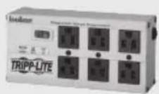
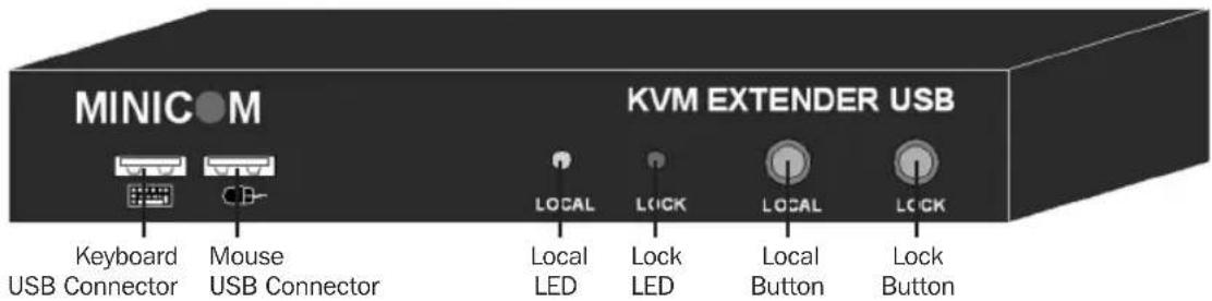
4.1 Transmitter Button / LEDs
| Button / LED Function | |
| Lock button Press to | keep control of the connected computer at the Transmitter position. |
| Control LED Blinks when | Transmitter position has control of the Transmitter position computer.Note: In order to have control of the transmitter (local) PC peripherals (keyboard + mouse), the remote (receiver's) local button must be pressed and the local LED on the receiver unit must be solid green. |
| Lock LED Blinks after | either Transmitter or Receiver position presses the Lock button for control. |
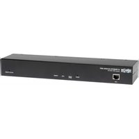
Transmitter front panel
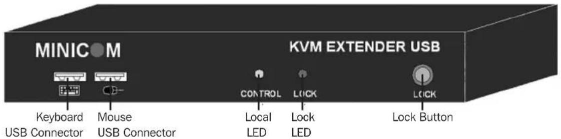
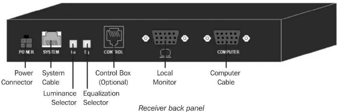
Transmitter back panel
4. KVM Extender USB Units
4.2 Receiver Buttons / LEDs
The Receiver can be located up to 500 ft. (150 m) away from the Transmitter.
| Button / LED Function | |
| Lock button Press to | lock control of the Transmitter computer at the Receiver position. |
| Local button Press to | toggle control between the local Receiver computer and the remote Transmitter computer (See section 9.1: Keyboard Hotkeys). |
| Lock LED Blinks after | either Transmitter or Receiver position presses the Lock button for control. |
| Local LED Blinks when | Receiver position has control of the Receiver position computer. Illuminates solid green to indicate receiver has control of the transmitter-connected peripherals (keyboard + mouse). |
Receiver front panel
5. Pre-Installation Instructions
Place cables away from fluorescent lights, air conditioners, and equipment that is likely to generate electrical noise.
This unit is not hot-swappable. If any disconnection or new connections are made, the user must power cycle both the PCs and the units.
6. Connecting the System
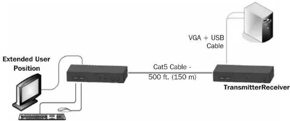
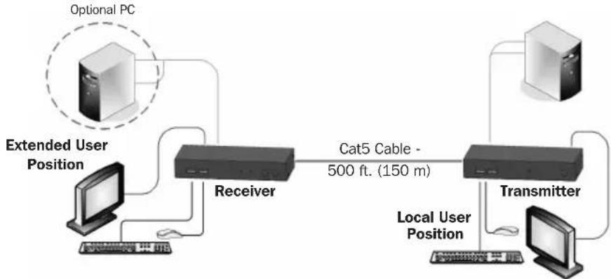
When using the system as an extender, connect the system as shown in Figure 6-1. The connections are explained below.
flowchart
graph LR
    A["Extended User Position"] --> B["Cat5 Cable - 500 ft. (150 m)"]
    B --> C["TransmitterReceiver"]
    C --> D["VGA + USB Cable"]
Figure 6-1: KVM Extender USB as an extender
6.1 Connecting the Transmitter
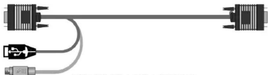
Connect a VGA + USB + PS/2 cable (Figure 6-2) to the Transmitter and a computer. Connect the HD15 connector to the Transmitter Computer port and connect the VGA and USB connectors to the local computer Monitor and USB ports. If you wish to utilize your computer's PS/2 ports, connect the included USB-to-PS/2 (keyboard) adapter to the USB-A portion of the VGA + USB + PS/2 cable.
natural_image
Pure electrical connector diagram showing two connectors connected by a cable, with no text or symbols present.Figure 6-2: VGA + USB + PS/2 Cable
6.2 Connecting a KVM Workstation to the Receiver
Connect a KVM workstation to the Receiver. Connect a keyboard and mouse to the Receiver Keyboard and Mouse USB ports. Connect a monitor to the Receiver Monitor port.
6.3 Connecting the System Cable
Connect the System cable CAT5/6/7 FTP cable to the System ports of the Transmitter and Receiver.
6.4 Connecting to the Power Supply
The Transmitter receives its power from the connected computer and does not generally need an external power supply. However, when the Transmitter is connected to a KVM switch, it may need an external power supply. If additional power is needed, use a ODT60001-AC-INT (not included, purchase separately).
Connect the Receiver to utility power with the external power supply provided.
7. Extender System with Optional Computer at Receiver Position
You can connect a computer to the Receiver position. The Receiver position can then either control the local computer or the Transmitter position computer (Figure 7-1).
flowchart
graph TD
    A["Optional PC"] --> B["Receiver"]
    B --> C["Transmitter"]
    C --> D["Computer"]
    E["Extended User Position"] --> B
    F["Local User Position"] --> C
    G["Cat5 Cable - 500 ft. (150 m)"] --> C
Figure 7-1: Extender system with optional computer at Receiver position
The connections are the same as outlined above, with the addition of a computer connected to the Receiver as follows:
Connect a VGA + USB + PS/2 cable to the Receiver and a computer. Connect the HD15 connector to the Receiver Computer port and connect the VGA and USB connectors to the computer Monitor and USB ports. If you wish to utilize your computer's PS/2 ports, connect the included USB-to-PS/2 (keyboard) adapter to the USB-A portion of the VGA + USB + PS/2 cable.
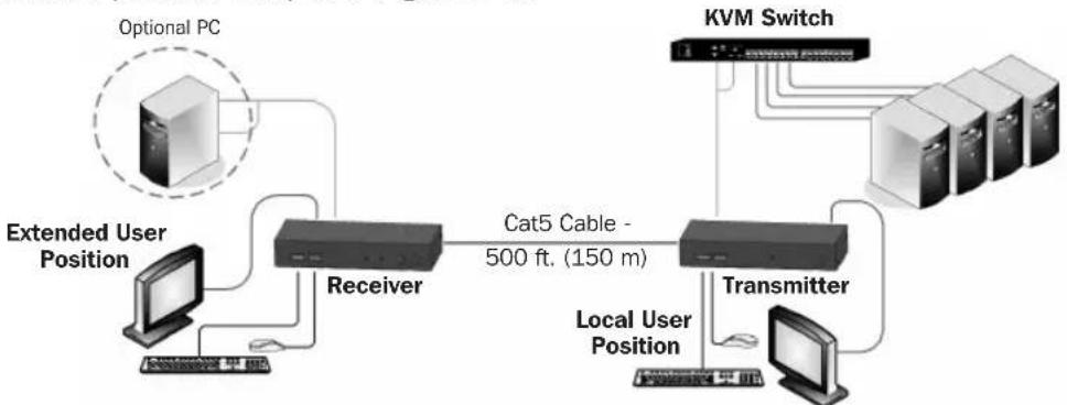
8. Extender + KVM Switch System with Optional Computer at Receiver Position
You can connect a KVM switch to the Receiver position. The Receiver position can then either control the local computer or any computer connected to the KVM switch at the Transmitter position computer (Figure 8-1).
flowchart
graph TD
    A["Extended User Position"] --> B["Receiver"]
    B --> C["Cat5 Cable - 500 ft. (150 m)"]
    C --> D["Transmitter"]
    D --> E["KVM Switch"]
    F["Optional PC"] -.-> B
    G["Local User Position"] --> D
    H["Computer"] --> B
    I["Computer"] --> D
Figure 8-1: Extender + KVM switch with optional computer at Receiver position
The connections are the same as outlined above, with the addition of a KVM switch connected to the Transmitter as follows:
Connect a VGA + USB + PS/2 cable to the Transmitter and the KVM switch. Connect the HD15 connector to the Transmitter Computer port and connect the VGA and USB connectors to the KVM switch Monitor and USB ports. If you wish to utilize your computer's PS/2 ports, connect the included USB-to-PS/2 (keyboard) adapter to the USB-A portion of the VGA + USB + PS/2 cable.
9. Operating the KVM Extender USB System
The system works on a first-come, first-served basis – press the keyboard or move the mouse at either the Transmitter (where relevant) or Receiver position to take control of the Transmitter position computer.
Transmitter Position: Press the Lock button to keep/gain control of the computer at the Transmitter position. The Lock LED at the Transmitter position illuminates and blinks at the Receiver position. The Control LED at the Transmitter position illuminates.
Receiver Position: Press the Lock button to keep control of the Transmitter computer at the Receiver position. The Lock LED at the Receiver position illuminates and blinks at the Transmitter position.
Press the Local button to gain control of the Receiver computer position. The Local LED blinks.
Note: You can only gain control by pressing the Lock button if the Lock LED is currently not blinking. Pressing the Lock button again at either position releases control and the Lock LEDs turn off.
9.1 Keyboard Hotkeys
To toggle between the Transmitter and the Receiver position, press: Caps Lock twice, release, then press C.
To turn the beeper sound on/off, press: Caps Lock twice, release, then press B.
9.2 Adjusting the Picture
To adjust the picture quality, use the included screwdriver to turn the Luminance and Equalization Picture adjusters located on the Receiver's rear panel.
10. Specifications
| System Cable Cat5/6/7 FTP 2x4x24 AWG solid-wire cable | |
| Maximum Distance 500 ft. (150 m) | |
| Mouse Support USB mouse | |
| Operating Systems Supported All major operating systems | |
| Management Push button or external control unit | |
| Screen Resolution Up to 1600 x 1200 @ 75 Hz | |
| Operating Temperature 32° to 104°F (0° to 40°C) | |
| Storage Temperature -40°F to 104°F (-40° to 40°C) | |
| Warranty Period 3-year limited | |
10. Specifications
| Transmitter Receiver | ||
| Cables & Connectors | HD15(F) (VGA + USB + PS/2 cable) – for computer or KVM switch | HD15(F) (VGA + USB + PS/2 cable) – for optional local computer |
| USB-A (F) to PS/2 (M) for keyboard connection | USB-A (F) to PS/2 (M) for keyboard connection | |
| USB X 2: for keyboard + mouse USB X 2: for keyboard + mouse | ||
| HD15 : for monitor HD15 : for monitor | ||
| RJ45 – System RJ45 – System | ||
| RJ11 – External control unit RJ11 – External control unit | ||
| Dimensions | 3.3 x 4.4 x 0.98 in. (84 x 112 x 25 mm) | 3.3 x 4.4 x 0.98 in. (84 x 112 x 25 mm) |
| Shipping Weight | 3.9 lb. (1.75 kg) | |
| Power Supply | From computer or external power supply (model ODT60001-AC-INT, sold separately) | Included external power supply (12VDC 1A) |
11. Warranty and Product Registration
3-Year Limited Warranty
TRIPP LITE warrants its products to be free from defects in materials and workmanship for a period of three (3) years from the date of initial purchase. TRIPP LITE's obligation under this warranty is limited to repairing or replacing (at its sole option) any such defective products. To obtain service under this warranty, you must obtain a Returned Material Authorization (RMA) number from TRIPP LITE or an authorized TRIPP LITE service center. Products must be returned to TRIPP LITE or an authorized TRIPP LITE service center with transportation charges prepaid and must be accompanied by a brief description of the problem encountered and proof of date and place of purchase. This warranty does not apply to equipment, which has been damaged by accident, negligence or misapplication or has been altered or modified in any way.
EXCEPT AS PROVIDED HEREIN, TRIPP LITE MAKES NO WARRANTIES, EXPRESS OR IMPLIED, INCLUDING WARRANTIES OF MERCHANTABILITY AND FITNESS FOR A PARTICULAR PURPOSE.
Some states do not permit limitation or exclusion of implied warranties; therefore, the aforesaid limitation(s) or exclusion(s) may not apply to the purchaser.
EXCEPT AS PROVIDED ABOVE, IN NO EVENT WILL TRIPP LITE BE LIABLE FOR DIRECT, INDIRECT, SPECIAL, INCIDENTAL OR CONSEQUENTIAL DAMAGES ARISING OUT OF THE USE OF THIS PRODUCT, EVEN IF ADVISED OF THE POSSIBILITY OF SUCH DAMAGE. Specifically, TRIPP LITE is not liable for any costs, such as lost profits or revenue, loss of equipment, loss of use of equipment, loss of software, loss of data, costs of substitutes, claims by third parties, or otherwise.
Product Registration
Visit tripplite.com/warranty today to register your new Tripp Lite product. You'll be automatically entered into a drawing for a chance to win a FREE Tripp Lite product!*
* No purchase necessary. Void where prohibited. Some restrictions apply. See website for details.
WEEE Compliance Information for Tripp Lite Customers and Recyclers (European Union)

Under the Waste Electrical and Electronic Equipment (WEEE) Directive and implementing regulations, when customers buy new electrical and electronic equipment from Tripp Lite they are entitled to:
- Send old equipment for recycling on a one-for-one, like-for-like basis (this varies depending on the country)
- Send the new equipment back for recycling when this ultimately becomes waste
Tripp Lite has a policy of continuous improvement. Specifications are subject to change without notice. Photos and illustrations may differ slightly from actual products.

1111 W. 35th Street, Chicago, IL 60609 USA • tripplite.com/support
19-09-354 93-36F4_RevA
1111 W. 35th Street, Chicago, IL 60609 EE. UU. • tripplite.com/support
19-09-354 93-36F4_rev8
1111 W. 35th Street, Chicago, IL 60609 USA • tripplite.com/support
1111 W. 35th Street, Chicago, IL 60609 USA • tripplite.com/support
19-09-354 93-36F4_revA
1111 W. 35th Street, Chicago, IL 60609 USA • tripplite.com/support
1111 W. 35th Street, Chicago, IL 60609 USA • tripplite.com/support
19-09-354 93-36F4_revA


- Important Safety Instructions
- Product Features
- Package Contents
- KVM Extender USB Units
- Transmitter Button / LEDs
- Receiver Buttons / LEDs
- Pre-Installation Instructions
- Connecting the System
- Connecting the Transmitter
- Connecting a KVM Workstation to the Receiver
- Connecting the System Cable
- Connecting to the Power Supply
- Extender System with Optional Computer at Receiver Position
- Extender + KVM Switch System with Optional Computer at Receiver Position
- Operating the KVM Extender USB System
- Keyboard Hotkeys
- Adjusting the Picture
- Specifications
- Warranty and Product Registration
- 3-Year Limited Warranty
- Product Registration
- WEEE Compliance Information for Tripp Lite Customers and Recyclers (European Union)
Brand : Tripp Lite
Model : 0DT60001
Category : Switch