STINGER 10 G3 WMB 1 - Speaker LD Systems - Free user manual and instructions
Find the device manual for free STINGER 10 G3 WMB 1 LD Systems in PDF.
User questions about STINGER 10 G3 WMB 1 LD Systems
0 question about this device. Answer the ones you know or ask your own.
Ask a new question about this device
Download the instructions for your Speaker in PDF format for free! Find your manual STINGER 10 G3 WMB 1 - LD Systems and take your electronic device back in hand. On this page are published all the documents necessary for the use of your device. STINGER 10 G3 WMB 1 by LD Systems.
USER MANUAL STINGER 10 G3 WMB 1 LD Systems
MANUFACTURER’S DECLARATIONS 18
ENGLISH YOU‘VE MADE THE RIGHT CHOICE! We have designed this product to operate reliably over many years. LD Systems stands for this with its name and many years of experience as a manufacturer of high-quality audio products. Please read this User‘s Manual carefully, so that you can begin making optimum use of your LD Systems product quickly. You can find more information about LD-SYSTEMS at our Internet site WWW.LD-SYSTEMS.COM PREVENTIVE MEASURES
1. Please read these instructions carefully.
2. Keep all information and instructions in a safe place.
3. Follow the instructions.
4. Observe all safety warnings. Never remove safety warnings or other information from the equipment.
5. Use the equipment only in the intended manner and for the intended purpose.
6. Use only sufficiently stable and compatible stands and/or mounts (for fixed installations). Make certain that wall mounts are properly installed and secured. Make certain that the equipment is installed securely and cannot fall down.
7. During installation, observ e the applicable safety regulations for your country.
8. Never install and operate the equipment near radiators, heat registers, ovens or other sources of heat. Make certain that the equipment is always installed so that is cooled sufficiently and cannot overheat.
9. Never place sources of ignition, e.g., burning candles, on the equipment.
10. Ventilation slits must not be blocked.
11. Keep a minimum distance of 20 cm around and above the device.
12. Do not use this equipment in the immediate vicinity of water (does not apply to special outdoor equipment - in this case, observe the special instructions noted below. Do not expose this equipment to flammable materials, fluids or gases. Avoid direct sunlight! 13. Make certain that dripping or splashed water cannot enter the equipment. Do not place containers filled with liquids, such as vases or drinking vessels, on the equipment.
14. Make certain that objects cannot fall into the device.
15. Use this equipment only with the accessories recommended and intended by the manufacturer.
16. Do not open or modify this equipment.
17. After connecting the equipment, check all cables in order to prevent damage or accidents, e.g., due to tripping hazards. 18. During transport, make certain that the equipment cannot fall down and possibly cause property damage and personal injuries. 19. If your equipment is no longer functioning properly, if fluids or objects have gotten inside the equipment or if it has been damaged in anot her way, switch it off immediately and unplug it from the mains outlet (if it is a powered device). This equipment may only be repaired by authorized, qualified personnel.
20. Clean the equipment using a dry cloth.
21. Comply with all applicable disposal laws in your country. During disposal of packaging, please separate plastic and paper/cardboard.
22. Plastic bags must be kept out of reach of children.
23. Please note that changes or modifications not expressly approved by the party responsible for compliance could void the user´s authority to operate the equipment. FOR EQUIPMENT THAT CONNECTS TO THE POWER MAINS 24. CAUTION: If the power cord of the device is equipped with an earthing contact, then it must be connected to an outlet with a protective ground. Never deactivate the protective ground of a power cord. 25. If the equipment has been exposed to strong fluctuations in temperature (for example, after transport), do not switch it on immediately. Moisture and condensation could damage the equipment. Do not switch on the equipment until it has reached room temperature. 26. Before connecting the equipment to the power outlet, first verify that the mains voltage and frequency match the values specified on the equipment. If the equipment has a voltage selection switch, connect the equipment to the power outlet only if the equipment values and the mains power values match. If the included power cord or power adapter does not fit in your wall outlet, contact your electrician. 27. Do not step on the power cord. Make certain that the power cable does not become kinked, especially at the mains outlet and/or power adapter and the equipment connector. 28. When connecting the equipment, make certain that the power cord or power adapter is always freely accessible. Always disconnect the equipment from the power supply if the equipment is not in use or if you want to clean the equipment. Always unplug the power cord and power adapter from the power outlet at the plug or adapter and not by pulling on the cord. Never touch the power cord and power adapter with wet hands. 29. Whenever possible, avoid switching the equipment on and off in quick succession because otherwise this can shorten the useful life of the equipment. 30. IMPORTANT INFORMATION: Replace fuses only with fuses of the same type and rating. If a fuse blows repeatedly, please contact an authorised service centre. 31. To disconnect the equipment from the power mains completely, unplug the power cord or power adapter from the power outlet. 32. If your device is equipped with a Volex power connector, the mating Volex equipment connector must be unlocked before it can be removed. However, this also means that the equipment can slide and fall down if the power cable is pulled, which can lead to personal injuries and/or other damage. For this reason, always be careful when laying cables. 33. Unplug the power cord and power adapter from the power outlet if there is a risk of a lightning strike or before extended periods of disuse. ITALIANOPOLSKIESPAÑOL FRANCAISDEUTSCHENGLISH4 CAUTION: To reduce the risk of electric shock, do not remove cover (or back). There are no user serviceable parts inside. Maintenance and repairs should be exclusively carried out by qualified service personnel. The warning triangle with lightning symbol indicates dangerous uninsulated voltage inside the unit, which may cause an electrical shock. The warning triangle with exclamation mark indicates important operating and maintenance instructions. Warning! This symbol indicates a hot surface. Certain parts of the housing can become hot during operation. After use, wait for a cool-down period of at least 10 minutes before handling or transporting the device. Warning! This device is designed for use below 2000 metres in altitude. Warning! This product is not intended for use in tropical climates. CAUTION! HIGH VOLUMES IN AUDIO PRODUCTS! This device is meant for professional use. Therefore, commercial use of this equipment is subject to the respectively applicable national accident prevention rules and regulations. As a manufacturer, Adam Hall is obligated to notify you formally about the existence of potential health risks. Hearing damage due to high volume and prolonged exposure: When in use, this product is capable of producing high sound-pressure levels (SPL) that can lead to irreversible hearing damage in performers, employees, and audience members. For this reason, avoid prolonged exposure to volumes in excess of 90 dB. NOTE: This equipment has been tested and found to comply with the limits for a Class B digital device, pursuant to Part 15 of the FCC Rules. These limits are designed to provide reasonable protection against harmful interference in a residential installation. This equipment generates, uses and can radiate radio frequency energy and, if not installed and used in accordance with the instructions, may cause harmful interference to radio communications. However, there is no guarantee that interference will not occur in a particular installation. If this equipment does cause harmful interference to radio or television reception, which can be determined by turning the equipment off and on, the user is encouraged to try to correct the interference by one or more of the following measures: - Reorient or relocate the receiving antenna. - Increase the separation between the equipment and receiver. - Connect the equipment into an outlet on a circuit different from that to which the receiver is connected. - Consult the dealer or an experienced radio/TV technician for help. Important: Before any assembly, check that all installation kit components are complete, undamaged and work correctly (split pins, screws, bolts, nuts, locking pins, steel hooks, retaining sockets and threads in speakers, etc.). Should any installation kit component be damaged, missing or not function properly, the installation kit should not be used. An M8 thread is situated on the rear side of the speaker for the installation of a secondary safety component. DEUTSCHFRANCAIS ESPAÑOL ENGLISH ITALIANO POLSKI5 OVERVIEW Product number Suitable for Installation Type LDEB82G3WMB LDEB82G3 LDEB82AG3 Wall & ceiling LDEB102G3WMB LDEB102G3 LDEB102AG3 LDEB282G3WMB LDEB282G3 LDEB282AG3 LDEBG3WMB
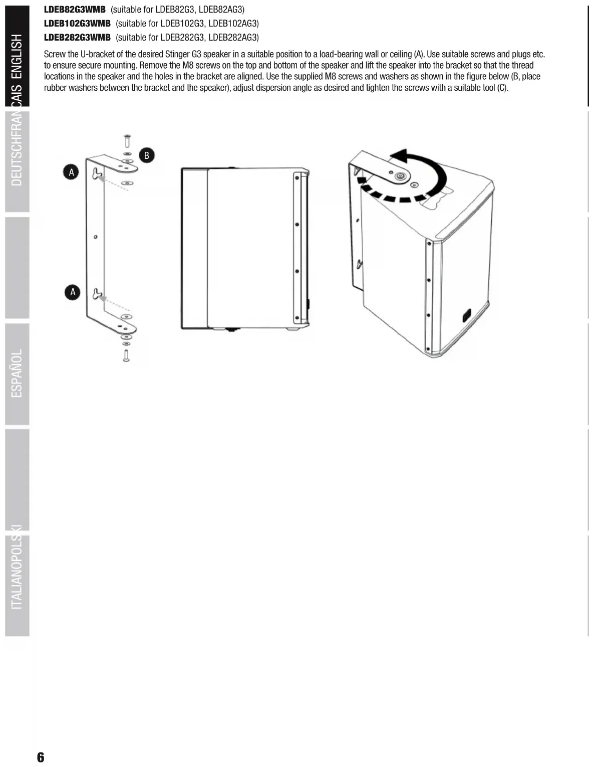
LDEB82G3WMB (suitable for LDEB82G3, LDEB82AG3) LDEB102G3WMB (suitable for LDEB102G3, LDEB102AG3) LDEB282G3WMB (suitable for LDEB282G3, LDEB282AG3) Screw the U-bracket of the desired Stinger G3 speaker in a suitable position to a load-bearing wall or ceiling (A). Use suitable screws and plugs etc. to ensure secure mounting. Remove the M8 screws on the top and bottom of the speaker and lift the speaker into the bracket so that the thread locations in the speaker and the holes in the bracket are aligned. Use the supplied M8 screws and washers as shown in the figure below (B, place rubber washers between the bracket and the speaker), adjust dispersion angle as desired and tighten the screws with a suitable tool (C). DEUTSCHFRANCAIS ESPAÑOL ENGLISH ITALIANO POLSKI7
LDEBG3WMB (suitable for LDEB122G3, LDEB122AG3, LDEB152G3, LDEB152AG3) Screw the adjustable U-bracket (in a suitable position) to a load-bearing wall or ceiling (A). Use suitable screws and plugs etc. to ensure secure mounting. The 35mm mounting stud can be installed on the bracket at four different distances from the wall (or ceiling). Select the appropriate position for the speaker and screw it tightly to the bracket (B, position the supplied rubber ring on the mounting stud). Remove the M10 screw on the top of the loudspeaker and lift the speaker into the bracket so that the 35mm mounting stud sits in the 0° flange of the speaker (C). Now set the adjustable side of the bracket to the appropriate size for the speaker and secure it with the two screws on the side of the bracket (D). Using the supplied M10 T-screw in the correct position directly opposite the mounting stud, position the speaker at the desired angle in the bracket (E, place supplied rubber washer between bracket and speaker. For permanent installation an M10 Allen screw is supplied). For traverse-installation, mounting holes for traverse clamps are situated at positions corresponding to speaker size (F). ITALIANOPOLSKIESPAÑOL FRANCAISDEUTSCHENGLISH8
1. Remove the two M6 screws A on the back of the speaker.
2. Slightly loosen bolt E on the wall bracket (do not remove), loosen and remove bolt D from the tilt & swivel arm, remove it and lift the U-bracket B from its mounting. Attach the U-bracket B to the rear of the speaker with the supplied screws. 3. Using screws, attach mounting plate C vertically in a suitable position to a solid wall with its flat side and safety eyelet facing upwards (4 screws). Use suitable screws and plugs etc. to ensure secure mounting. 4. Now slide the speaker with the attached U-bracket B into the bracket on the wall, reinstall bolt D into its designated position and secure it with the previously removed nut. 5. The speaker can be tilted vertically by slightly loosening nut E, adjusting to the desired angle and then re-tightening the nut. The speaker can be adjusted horizontally by loosening nut F (remove plastic cap beforehand), adjusting the angle as required, and then re-tightening the nut.
LDEB82AG3WMB1 (suitable for LDEB82AG3) 1. Remove four M4 screws A on the back of the speaker in the positions for fastening the adapter plate. Ensure that the cutouts for the LINE OUT jack and POWER switch are correctly positioned. Attach the adapter plate to the speaker with the supplied M4 screws so that the LINE OUT jack and POWER switch are freely accessible. 2. Slightly loosen bolt E on the wall bracket (do not remove), loosen and remove bolt D from the tilt & swivel arm, remove it and lift the U-bracket B from its mounting. Attach the U-bracket B to the rear of the adapter plate with the supplied nuts. 3. Using screws, attach mounting plate C vertically in a suitable position to a solid wall with its flat side and safety eyelet facing upwards (4 screws). Use suitable screws and plugs etc. to ensure secure mounting. 4. Now slide the speaker with the attached U-bracket B into the bracket on the wall, reinstall bolt D into its designated position and secure it with the previously removed nut. 5. The speaker can be tilted vertically by slightly loosening nut E, adjusting to the desired angle and then re-tightening the nut. The speaker can be adjusted horizontally by loosening nut F (remove plastic cap beforehand), adjusting the angle as required, and then re-tightening the nut. DEUTSCHFRANCAIS ESPAÑOL ENGLISH ITALIANO POLSKI9
1. Remove the four M6 screws A on the back of the speaker.
2. Slightly loosen bolt E of the wall bracket (do not remove), loosen and remove bolt D from the tilt & swivel arm, remove and lift the U-bracket with mounting plate B from its mounting. Attach the U-bracket with mounting plate B to the rear of the speaker with the supplied screws. 3. Using screws, attach mounting plate C vertically in a suitable position to a solid wall with its flat side and safety eyelet facing upwards (8 screws). Use suitable screws and plugs etc. to ensure secure mounting. 4. Now slide the speaker with the attached U-bracket with mounting plate B into the bracket on the wall, reinstall bolt D into its designated position and secure it with the previously removed nut. 5. The speaker can be tilted vertically by slightly loosening nut E, adjusting to the desired angle and then re-tightening the nut. The speaker can be adjusted horizontally by loosening nut F (remove plastic cap beforehand), adjusting the angle as required, and then re-tightening the nut. ITALIANOPOLSKIESPAÑOL FRANCAISDEUTSCHENGLISH10
LDEB282AG3WMB1 (suitable for LDEB282AG3) 1. Remove six M4 screws A on the back of the speaker in the positions for fastening the adapter plate. Ensure that the cutouts for the LINE OUT jack and POWER switch are correctly positioned. Attach the adapter plate to the speaker with the supplied M4 screws so that the LINE OUT jack and POWER switch are freely accessible. 2. Slightly loosen bolt E on the wall bracket (do not remove), loosen and remove bolt D from the tilt & swivel arm, remove it and lift the U-bracket B from its mounting. Attach the U-bracket B to the rear of the adapter plate with the supplied nuts. 3. Using screws, attach mounting plate C vertically in a suitable position to a solid wall with its flat side and safety eyelet facing upwards (8 screws). Use suitable screws and plugs etc. to ensure secure mounting. 4. Now slide the speaker with the attached U-bracket B into the bracket on the wall, reinstall bolt D into its designated position and secure it with the previously removed nut. 5. The speaker can be tilted vertically by slightly loosening nut E, adjusting to the desired angle and then re-tightening the nut. The speaker can be adjusted horizontally by loosening nut F (remove plastic cap beforehand), adjusting the angle as required, and then re-tightening the nut. DEUTSCHFRANCAIS ESPAÑOL ENGLISH ITALIANO POLSKI11
1. Remove the four M6 screws A on the back of the speaker.
2. Slightly loosen bolt E of the wall bracket (do not remove), loosen and remove bolt D from the tilt & swivel arm, remove and lift the U-bracket with mounting plate B from its mounting. Attach the U-bracket with mounting plate B to the rear of the speaker with the supplied screws. 3. Using screws, attach mounting plate C vertically in a suitable position to a solid wall with its flat side and safety eyelet facing upwards (4 screws). Use suitable screws and plugs etc. to ensure secure mounting. 4. Now slide the speaker with the attached U-bracket with mounting plate B into the bracket on the wall, reinstall bolt D into its designated position and secure it with the previously removed nut. 5. The speaker can be tilted vertically by slightly loosening nut E, adjusting to the desired angle and then re-tightening the nut. The speaker can be adjusted horizontally by loosening nut F (remove plastic cap beforehand), adjusting the angle as required, and then re-tightening the nut. ITALIANOPOLSKIESPAÑOL FRANCAISDEUTSCHENGLISH12
1. Remove the four M6 screws A on the back of the speaker.
2. Slightly loosen bolt E of the wall bracket (do not remove), loosen and remove bolt D from the tilt & swivel arm, remove and lift the U-bracket with mounting plate B from its mounting. Attach the U-bracket with mounting plate B to the rear of the speaker with the supplied screws. 3. Using screws, attach mounting plate C vertically in a suitable position to a solid wall with its flat side and safety eyelet facing upwards (8 screws). Use suitable screws and plugs etc. to ensure secure mounting. 4. Now slide the speaker with the attached U-bracket with mounting plate B into the bracket on the wall, reinstall bolt D into its designated position and secure it with the previously removed nut. 5. The speaker can be tilted vertically by slightly loosening nut E, adjusting to the desired angle and then re-tightening the nut. The speaker can be adjusted horizontally by loosening nut F (remove plastic cap beforehand), adjusting the angle as required, and then re-tightening the nut. DEUTSCHFRANCAIS ESPAÑOL ENGLISH ITALIANO POLSKI13 LDEBG3TMB (suitable for LDEB122G3, LDEB122AG3, LDEB152G3, LDEB152AG3)
ASSEMBLY OF THE MOUNTING BRACKET AND TRAVERSE CLAMP 1. Release the safety splint (A) from the two M8 screws (B, C) in the cylindrical pivot/tilt head (D) of the mounting bracket. 2. Unscrew the two screws (B, C) from the pivot/tilt head (D), separate the two cylinder halves and remove the cast piece (E). 3. Now use the parts included – the M10 screw (F), spring washer (G) and self-locking M10 nut (H) – to attach the cast piece (E) firmly to the traverse clamp (I) using a 17 mm socket tool. To do so, place the traverse clamp in the recess of the cast piece and the self-locking nut in the recess of the traverse clamp and then insert the screw with the spring washer through the cast piece into the traverse clamp (see illustration). 4. Now place the cast piece with the traverse clamp into one half of the pivot/tilt head (D) and join the two halves in such a way that the M8 screw (C) can be placed through the appropriate installation hole of the one half, through the support rail (J) of the mounting bracket and through the installation hole of the cylindrical pivot/tilt head. Place the previously removed washer on the screw and finger tighten the M8 nut. Secure the nut using the previously released safety splint (A). 5. Put the M8 washer onto the M8 lever screw (B), taking care to ensure that the M8 nut is correctly placed in the recess of the appropriate cylinder half of the pivot/tilt head. Insert the lever screw through the two cylinder halves and tighten. Secure the screw using a previously released safety splint (A). ITALIANOPOLSKIESPAÑOL FRANCAISDEUTSCHENGLISH14
Traverse clamp for mounting on a horizontal traverse.
Wing nut for clamping to a traverse.
T-screw to lock the horizontal and vertical axes
Mounting rail with slots to adjust the vertical dispersion of the speaker.
Rotation mechanism for adjusting the horizontal dispersion of the speaker.
Three steel hooks which insert into the retaining sockets on the top of the speaker.
Two spring-loaded locking pins to secure the connection.
Mounting holes for alternative installation of the speaker with chains. Important: Before any assembly, check that all mounting bracket components are complete, undamaged and work correctly (split pins, screws, bolts, nuts, locking pins, steel hooks, retaining sockets in speakers, etc.). Should any mounting bracket component be damaged, missing or not function properly, the mounting bracket should not be used. DEUTSCHFRANCAIS ESPAÑOL ENGLISH ITALIANO POLSKI15
Insert all three steel hooks of the EasyMount bracket into the corresponding retaining sockets on the speaker.
Slide the entire bracket towards the back of the speaker.
When installing the mounting bracket, ensure that the spring-loaded locking pins engage fully. Ensure that locking pins are functioning correctly before every installation. For safety reasons, both locking pins must be pulled upwards simultaneously to release the connection (two-hand release).
Before attaching the speaker to a traverse, tighten the T-screw on the mounting bracket No. 3. Using traverse clamp No.1, suspend the speaker from a horizontal traverse in a suitable position, and fasten it into place with wing nut No. 2.
Loosen T-screw No. 3 slightly (approximately 1 turn). To adjust the vertical dispersion of the speaker, lift the speaker slightly and slide the notched mounting rail No.4 into the desired tilt position. Release the speaker to allow the retaining pin No. 5 to engage in the corresponding notch.
Turn the speaker until the desired horizontal dispersion is achieved and tighten T-screw No. 3. ITALIANOPOLSKIESPAÑOL FRANCAISDEUTSCHENGLISH16
Traverse clamp with adjustable T-screw and flange for mounting pin (only for mounting on horizontal traverses).
Mounting pin with M10 thread and wing nut.
Adapter for attaching the clamp to square-section tubes.
Remove the M10 screw on the top of the speaker.
Remove the M10 wing nut from the mounting pin (No. 2) and screw it fully into the M10 thread on the top of the speaker.
Attach the traverse clamp to a traverse with the adjustable T-screw in a suitable position and ensure a firm grip.
Loosen the locking screw so far that the flange on the underside of the clamp can accept the mounting pin (do not remove the bolt).
Push the spring-loaded locking pins on the side of the clamp into the housing so that the flange on the underside of the clamp can accept the mounting pin and push the pin all the way into the flange. Release the pressure from the locking pin and keep hold of the speaker until you are certain that the mounting pin is fully engaged. Rotate the speaker to achieve the desired dispersion and secure the connection by tightening the locking screw No. 7. DEUTSCHFRANCAIS ESPAÑOL ENGLISH ITALIANO POLSKI17 Model name: LDEB82G3WMB LDEB102G3WMB Type: PA Loudspeaker Accessories PA Loudspeaker Accessories Part: Wall/Ceiling Mount Bracket Wall/Ceiling Mount Bracket Suitable for: LDEB82G3, LDEB82AG3 LDEB102G3, LDEB102AG3 Material: Steel Steel Surface: Powder Coated Powder Coated Colour: Black Black Max. Load 12 kg 15 kg Dimensions (W x H x D): 60mm x 460mm x 170mm 60mm x 535mm x 170mm Weight: 1.1 kg 1.2 kg Model name: LDEB282G3WMB LDEBG3WMB Type: PA Loudspeaker Accessories PA Loudspeaker Accessories Part: Wall/Ceiling Mount Bracket Wall/Ceiling/Truss Mount Bracket Suitable for: LDEB282G3, LDEB282AG3 LDEB122G3, LDEB122AG3
Material: Steel/Zinc Aluminium/Brass Surface: Powder Coated Powder Coated/Uncoated Colour: Black Black/Brass Max. Load 28 kg 20 kg Dimensions (W x H x D): 230mm x 240mm x 430mm 57mm x 136mm x 118mm Weight: 3 kg 0.564 kg