
ZIRD300 - Construction Equipment Zipper - Free user manual and instructions
Find the device manual for free ZIRD300 Zipper in PDF.

| Brand | Zipper |
| Model | ZI-RD300 |
| Product type | Mini dumper (construction vehicle) |
| Maximum load capacity | 300 kg |
| Maximum incline (direction of travel) | 15° |
| Maximum incline (lateral) | 10° |
| Engine type | 4-stroke petrol |
| Recommended fuel | Unleaded petrol ROZ 95 or higher |
| Recommended engine oil | SAE30, 15W40 or equivalent |
| Tire pressure | 2.1 bar (0.21 MPa) |
| Transmission | 3 forward speeds + 1 reverse (non-synchronized) |
| Steering | Lateral control levers |
| Dump bucket | Manual (tilting lever) |
| Clutch | Cable-operated, adjustable |
| Brake | Automatic brake when disengaging clutch |
| Maintenance: engine oil change | First change after 20 h, then every 100 h |
| Maintenance: air filter | Cleaning every 20-30 h |
| Maintenance: spark plug | Cleaning every 50 h |
| Warranty (non-commercial use) | 2 years |
| Warranty (commercial use) | 1 year |
| Spare parts | Available via Zipper (use genuine parts) |
| Required protective equipment | Gloves, helmet, goggles, hearing protection, safety shoes |
| Prohibited use | Transporting people, public roads, slopes >15° |
Frequently Asked Questions - ZIRD300 Zipper
User questions about ZIRD300 Zipper
0 question about this device. Answer the ones you know or ask your own.
Ask a new question about this device
Download the instructions for your Construction Equipment in PDF format for free! Find your manual ZIRD300 - Zipper and take your electronic device back in hand. On this page are published all the documents necessary for the use of your device. ZIRD300 by Zipper.
USER MANUAL ZIRD300 Zipper
natural_image
Green ZIPPER utility vehicle with four deep tires and black wheels (no visible text or symbols)
ZI-RD300
EAN: 9120039232485
1 INHALT/INDEX
1 INHALT/INDEX 2
2 SICHERHEITSZEICHEN / SAFETY SIGNS / SEÑALES DE SEGURIDAD / ZNAKOVI ZA SIGURNOST / SYMBOLES DE SECURITE / SIGURNOSNI ZNAKOVI / BIZTONSÁGI JELZÉS 6
3 TECHNIK/TECHNICS/DATOS TÉCNICOS/TEHNIKA/TECHNIQUE/TEHNOLOGIJA/TECHNIKA 9
3.1 Komponenten / components / Componentes / Komponente / Composants / Sastavni delovi / Alkatrészek....9
3.1 Lieferumfang/Delivery content/Entrega de la máquina/Opseg isporuke / Contenu de la livraison / Obim isporuke / Szállítási terjedelem ..... 10
3.2 Technische Daten / technical data / Ficha técnica / Tehnički podaci / Données techniques / Tehnički podaci / Můszaki adatok.... 11
4 VORWORT (DE) 13
5 SICHERHEIT 14
T1.1 Intended Use 27
11.2 Security instructions.... 28
11.3 Remaining risk factors.... 29
12 ASSEMBLY 30
12.1 Assembly....30
13 OPERATION 31
13.1 Operation instructions.... 31
13.2 Functions of components.... 31
13.3 Start up.... 32
13.3.1 Checking the engine oil level 32
13.3.2 Refuel 33
13.4 Operation.... 33
13.4.1 Start Engine....33
13.4.2 Idle speed....33
13.4.3 Stop the engine....33
14 MAINTENANCE 34
14.1 Maintenance plan 34
14.2 Cleaning.... 35
14.3 Engine 35
14.3.1 Engine oil exchange....35
14.4 Clutch 35
14.5 Steering 36
14.6 Tires 36
14.7 Gearbox 36
14.7.1 Check gearbox oil 36
14.8 Storage 36
14.9 Disposal 37
15 TROUBLE SHOOTING 37
16 PREFACIO (ES) 38
17 SEGURIDAD 39
30.1 Assemblage....67
31 FONCTIONNEMENT 68
32.7 Transmission....73
EN CE-Conformal! - This product complies with the EC-directives.
READ THE MANUAL! Read the user and maintenance manual carefully and get
EN familiar with the controls in order to use the machine correctly and to avoid injuries and machine defects.
EN ATTENTION! Ignoring the safety signs and warnings applied on the machine as well as ignoring the security and operating instructions can cause serious injuries and even lead to death.
EN Stop before any break and engine maintenance!
EN Protective clothing!
EN It is forbidden to remove the protection devices and safety devices.
EN Gasoline and oil are highly flammable and explosive! Do not smoke or have open flames near the machine!
EN Burn hazard! Keep away from hot parts on the machine!
EN Solid Objects can be thrown away!
EN Keep your hands and feet clear from all rotating parts!
| ZI-RD300 | |
| 1 | Motorschalter / engine switch / Interruptor del motor / Sklopka motora / Interrupteur moteur / Prekidač motora / Motorkapcsoló |
| 2 | Gashebel / throttle control / Acelerador / Ručica gasa / Poignée des gaz / Poluga gasa / Gázszabályozó kar |
| 3 | Rechter Steuerhebel / right steering lever / Palanca de dirección derecha / Desna upravljačka ručica / Levier de commande côté droit / Desna poluga upravljača / Jobb oldali kormánykar |
| 4 | Kupplungshebel / clutch control lever / Palanca de embrague / Ručica spojke / Levier d'accouplement / Poluga kvačila / Kuplungkar |
| 5 | Linker Steuerhebel / left steering lever / Palanca de dirección izquierda / Lijeva upravljačka ručica / Levier de commande côté gauche / Leva poluga upravljača / Bal oldali kormánykar |
| 6 | Kippbehälter / dump box / Caja basculante / Nagibni sanduk / Benne basculante / Kon-tejner za istovar / Billenőtartály |
| 7 | Gangschalthebel / gear selection lever / Palanca de cambio / Ručica mjenjača brzina / Levier de changement de vitesse / Ručiva menjača / Fokozatkapcsoló kar |
| 8 | Kipphebel / tipping handle / Palanca de inclinación / Ručica za naginjanje / Levier de bas-culement / Poluga za istovar / Billentókar |
| 9 | Rad / wheel / Ruedas / Kotač / Roue / Točak / Kerék |
| 10 | Getriebe / gearbox / Caja de cambios / Mjenjač / Transmission / Menjač / Hajtómů |
3.1 Lieferumfang/Delivery content/Entrega de la máquina/Opseg isporuke / Contenu de la livraison / Obim isporuke / Szállítási terjedelem

| 1 | Kippbehälter / dump boxCaja basculante / Nagibni sanduk / Benne basculante / Kontejner za istovar / Billenötartály | 4 | Räder rechts (2 Stück) / wheels right (2 pcs)Ruedas (2 unidades) / Kotači (2 komada) / Roues (2 pièces) / Točkovi desno (2 komada) / Jobb oldali kerekek (2 db) |
| 2 | Maschineneinheit / main frameBastidor principal / Okvir stroja / Unité de machine / Jedinica mašine / Gépegység | 5 | Betriebsanleitung / manualManual de instrucciones / uputa za uporabu / Mode d'emploi / Uputstvo za upotrebu / Használati útmutató |
| 3 | Räder links (2 Stück) / wheels left (2 pcs)Ruedas (2 unidades) / Kotači (2 komada) / Roues (2 pièces) / Točkovi levo (2 komada / Bal oldali kerekek (2 db | 6 | Kleinteileset / hardware bagSet de tornillos/piezas pequeñasKomplet sitnih dijelova / Jeu de petites pièces / Set malih delova / Apróalkatrész-készlet |

3.2 Technische Daten / technical data / Ficha técnica / Tehnički podaci / Données techniques / Tehnički podaci / Můszaki adatok
| ZI-RD300 | |
| Motor / engineMotor / Motor /Moteur / Motor / Motor | 1 Zylinder 4-Takt OHV MotorG200F |
| Motorleistung / engine powerPotencia del motor / Snaga motora /Puissance du moteur / Snaga motora / Motorteljesítmény | 4,1 kW (bei 3600min ^-1 ) |
| Hubraum / displacementCilindrada / Zapremnina / Cylindrée / Zapremina /Hengerürtartalom | 196 cm ^3 |
| Getriebestufen / transmissionVelocidades / Stupnjevi prijenosa / Niveaux d'engrenage /Nivoi menjača / Kapcsolási fokozatok | 3 V / 1R3 de avance / 1 de marcha atrás3 unaprijed / 1 unatrag3 avance / 1 marche arrière |
| Geschwindigkeit vorwärts min/maxForward speed min/maxVelocidades de avance min/maxBrzina unaprijed min/maks / Vitesse d'avance min./max. /Brzina napred min/maks. / Sebesség előre min/max | 1 / 6,4 km/h(I: max 2,5 | II: max. 4,8 | III: max. 6.4 km/h) |
| Geschwindigkeit rückwärts min/maxReverse speed min/maxVelocidad marcha atrás min/maxBrzina unatrag min/maks/Vitesse de marche arrière min./max. / Brzina nazad min/maks./ Tolatósebesség min/max | 0,7 / 2 km/h |
| Starter / starterArranquePokretač / Démarreur / Starter / Indító | Reversierstarter / recoil starterArranque por cablePokretač s užetom / Démarreur in-verseur / Povratni starter / Irányváltógomb |
| Drehzahl max / speed maxVelocidad max / Broj okretaja maks /Vitesse de rotation max. / Brzina maks. / Fordulatszám | 3600 min ^-1 |
| Leerlaufdrehzahl / idle speedVelocidad de ralentí / Broj okretaja praznog hoda /LRégime à vide / Broj obrtaja praznog hoda / Üresjáratifordulatszám | 1400 min ^-1 |
| Treibstoff / fuelCombustible / Gorivo / Carburant/Gorivo / Üzemanyag | Benzin unverbleit ROZ 95Unleaded fuel RON 95Gasolina sin plomo min. 95 octanosBezolovni benzin ROZ 95Essence sans plomb ROZ 95 / Bezolovni benzin RON 95 / ROZ 95-ös ólommentesbenzin |
| Treibstofftank / fuel tank capacityDepósito de combustibe / Spremnik goriva /Réservoir de carburant / Rezervoar goriva / Üzemanyagtartály | 3,6 l |
| Motoröl / engine oil typeTipo de aceite de motor / Motorno ulje / Huile du moteur /Motorno ulje / Motorolaj | 15W40, SAE30, 10W40 |
| Motoröltank / engine oil capacityDepósito de aceite / Spremnik motornog ulja /Réservoir d'huile moteur / Rezervoar motornog ulja / Motorolaj tartály | 0,6 l |
| Getriebeöl / gear oil typeTipo de aceite del engranaje / Ulje za prijenosnike /Huile de transmission / Ulje za menjač / Hajtómúolaj | 80W90, GL-5, GL-6, SAE80W-90 |
| Getriebeölmenge / gear oil capacityCapacidad de aceite del engranaje / Količina ulja za prijenosnik/ Quantité d'huile de transmission / Količina ulja za menjače /Hajtómúolaj mennyisége | 1,6 l |
| Bereifung / tires | 4.00-8 |
| Ruedas / Gume / Pneumatiques / Gume / Abroncsok | |
| Kippbehältermaße / dump box sizeDiemnsiones de la caja / Dimenzije nagibnog sanduka / Dimensions de la benne basculante / Dimenzije kontejnera za istovar / Billenőtartály mérete | 912 x 650 x 560 mm |
| Kippbehältervolumen / dump box capacityCapacidad de la caja / Volumen nagibnog sanduka /Volume de la benne basculante / Volumen kontejnera za istovar / Billenőtartály térfogata | 125 l |
| Kippeinrichtung / tilt functionFunción de inclinación / Naginjanje / Dispositif de basculement / Uređaj za naginjanje / Billenőberendezés | Manuell / manuelyManual / ručno / Manuel / Ručno / Kézi |
| Ladegewicht max / load capacity maxCarga de peso máximo / Maks. težina tereta /Poids de charge max. / Tdyh žApošdobl [ŽA] Žj r6/ Maximális raksúly | 300 kg |
| Gewicht / weightPeso de la máquina / Težina /Poids / Težina / Súly | 145 kg |
| Maschinenmaße / machine dimensionDimensiones de la máquina / Dimenzije stroj / Dimensions de la machine / Dimenzije mašine / Gépméretek | 1330 x 810 x 1038 mm |
| Garantierter Schallleistungspegel /guaranteed sound power levelNivel de potencia acústicaZajamčena razina zvučne snage /Niveau de puissance acoustique garanti LWA / Garantovani nivo snage zvuka / Garantált hangteljesítményszint | 98 dB(A) |
| Vibration Handgriff / vibration handlebar / Vibración em-puñadura / Vibracije na dršc /Poignée de vibration / Vibraciona ručka / Fogantyú vibráció | 3.92 m/s2 k:1,5 m/s2 |
(DE) Hinweis Geräuschangaben: Die angegebenen Werte sind Emissionswerte und müssen damit nicht zugleich auch sichere Arbeitsplatzwerte darstellen. Obwohl es eine Korrelation zwischen Emissions- und Immissionspegeln gibt, kann daraus nicht zuverlässig abgeleitet werden, ob zusätzliche Vorsichtsmaßnahmen notwendig sind oder nicht. Faktoren, welche den am Arbeitsplatz tatsächlich vorhandenen Immissionspegel beeinflussen, beinhalten die Eigenart des Arbeitsraumes und andere Geräuschquellen, d. h. die Zahl der Maschinen und anderer benachbarter Arbeitsvorgänge. Die zulässigen Arbeitsplatzwerte können ebenso von Land zu Land variieren. Diese Information soll jedoch den Anwender befähigen, eine bessere Abschätzung von Gefährdung und Risiko vorzunehmen.
(EN) Notice noise emission: The values given are emission values and therefore do not have to represent safe workplace values at the same time. Although there is a correlation between emission and immission levels, it cannot be reliably deduced whether additional precautions are necessary or not. Factors influencing the actual immission level at the workplace include the nature of the workspace and other noise sources, i.e. the number of machines and other adjacent operations. The permissible workplace values may also vary from country to country. However, this information should enable the user to make a better assessment of hazard and risk.
(ES) Indicación sobre el ruido: Los valores especificados son valores de emisión y, por lo tanto, no representan necesariamente valores de seguridad en el lugar de trabajo. Aunque existe una correlación entre los niveles de emisión e inmisión, no se puede deducir de manera fiable si es necesario o no adoptar medidas de precaución adicionales. Entre los factores que influyen en el nivel de inmisión real en el lugar de trabajo se encuentran la naturaleza del espacio de trabajo y otras fuentes de ruido, es decir, el número de máquinas y otros procesos de trabajo adyacentes. Los valores permitidos en el lugar de trabajo también pueden variar de un país a otro. No obstante, esta información debería permitir al usuario hacer una mejor evaluación de los peligros y riesgos.
(HR) Napomena o emisiji buke: navedene vrijednosti su vrijednosti emisije i ne moraju istovremeno predstavljati i sigurne vrijednosti na radnom mjestu. Iako postoji korelacija između razina emisije i imisije, iz toga se ne može pouzdano zaključiti jesu li ili nisu potrebne dodatne mjere opreza. Čimbenici koji utječu na stvarnu razinu imisije na radnom mjestu obuhvaćaju specifičnost radnog prostora i druge izvore buke, tj. broj strojeva i drugih radnih procesa u bilzini. Dopuštene vrijednosti na radnom mjestu mogu se razlikovati i u različitim državama. Ali ove bi informacije korisniku trebale omogućiti da izvrši procjenu opasnosti i rizika.
(FR) Avis Données sur le bruit : Les valeurs indiquées sont des valeurs d'émission et ne représentent donc pas nécessairement des valeurs de sécurité sur le lieu de travail. Bien qu'il existe une corrélation entre les niveaux d'émission et d'immission, il est impossible de déduire de manière fiable si des mesures de précaution supplémentaires sont nécessaires ou non. Les facteurs influençant le niveau d'immission réellement présent sur le lieu de travail comprennent les caractéristiques de la salle de travail et d'autres sources de bruit, c'est-à-dire le nombre de machines et d'autres processus de travail adjacents. Les valeurs autorisées sur le lieu de travail peuvent également varier d'un pays à l'autre. Toutefois, ces informations devraient permettre à l'utilisateur de mieux évaluer le danger et le risque.
(SRB) Napomena o emisiji buke: Navedene vrednosti su vrednosti emisije i stoga ne moraju istovremeno da predstavljaju vrednosti sigurnog radnog mesta. Iako postoji korelacija između nivoa emisije i imisije, ne može se pouzdano zaključiti jesu li potrebne dodatne mere opreza ili ne. Faktori koji utiču na stvarni nivo imisije na radnom mestu uključuju prirodu radnog prostora i druge izvore buke, tj. broj mašina i drugih susednih radnih procesa. Takođe, dopuštene vrednosti na radnom mestu se mogu razlikovati od zemlje do zemlje. Međutim, te informacije bi trebale da omoguće korisniku bolju procenu opasnosti i mogućih rizika.
(HU) Zajra vonatkozó adatokkal kapcsolatos megjegyzés: A megadott értékek kibocsátási értékek és nem jelentik egyben a biztonságos munkahelyi értékeket. Habár van összefüggés a kibocsátási és az immissziós szintek között, ebből nem lehet megbízhatóan következtetni arra, hogy szükség van-e további óvintézkedésekre vagy sem. A munkahelyen ténylegesen jelen lévő immissziószintet befolyásoló tényezők közé tartoznak a munkaterület és egyéb zajforrások jellemzői, azaz a munkagépek száma és a szomszédban végzett egyéb munkafolyamatok. A megengedett munkahelyi értékek országonként változhatnak. Ezeknek az információknak azonban lehetővé kell tenniük a felhasználó számára a jobb veszély- és a kockázatértékelést.
4 VORWORT (DE)
natural_image
Technical line drawing of a four-wheeled robotic chassis with visible wheels and mounting components (no text or symbols)
A Räder:
natural_image
Line drawing of a small wheeled utility vehicle with visible wheels and a handle, shown with an inset close-up of the wheel assembly (no text or symbols)7 BETRIEB

This manual contains important information and advice for the correct and safe use and maintenance of the wheeled dumper ZI-RD300.
Following the usual commercial name of the device (see cover) is substituted in this manual with the name "machine".
The manual is part of the machine and may not be stored separately. Read it profoundly before first use of the machine and keep it for later reference. When the machine is handed to other persons always put the manual to the machine.
Please follow the security instructions!
Please read the entire manual, to prevent misunderstandings, machine damage or even injuries!
Due to continuous development of our products illustrations, pictures might differ slightly.
If you however find errors in this manual, please inform us.
Technical changes excepted!
Copyright law
© 2020
This manual is protected by copyright law – all rights reserved. Especially the reprinting as well as the translation and depiction of pictures will be prosecuted by law. Court of jurisdiction is the Landesgericht Linz or the competent court for 4707 Schlüsslberg, AUSTRIA.
Customer Support
The machine must only be used for its intended purpose! Any other use is deemed to be a case of misuse.
To use the machine properly you must also observe and follow all safety regulations, the assembly instructions, operating and maintenance instructions lay down in this manual.
All people who use and service the machine have to be acquainted with this manual and must be informed about the machine's potential hazards.
It is also imperative to observe the accident prevention regulations in force in your area.
The same applies for the general rules of occupational health and safety.
The machine is used for:
Small loading and transportation tasks in landscaping and agriculture.
Any manipulation of the machine or its parts is a misuse, in this case ZIPPER-MASCHINEN and its sales partners cannot be made liable for ANY direct or indirect damage.
Even when the machine is used as prescribed it is still impossible to eliminate certain residual risk factors.

WARNING
- Max. load 300kg
- Allowed tilt position in the direction of travel: 15°
- Allowed tilt position transverse to direction of travel: 10°
It is forbidden to remove the protection devices and safety devices! - Read also the separately packed operation manual of the engine manufacturer
Ambient conditions
The machine may be operated:
humidity max. 70%
temperature
+5^ to +40^ (+41^ to +104^)
Prohibited use
- The operation of the machine outside the stated technical limits described in this manual is forbidden.
- Operation of the machine function without any protection devices is forbidden.
• Any manipulation of the machine and parts is forbidden.
• The machine is not approved for transporting passengers
• The machine is not approved for public traffic! - Etwaige Änderungen in der Konstruktion der Maschine sind unzulässig.
- The use of the machine for any purposes other than described in this user-manual is forbidden.
- It is not allowed to leave the immediate work area during the work is being performed.!
11.2 Security instructions
Missing or non-readable security stickers have to be replaced immediately!
To avoid malfunction, machine defects and injuries, read the following security instructions!
The locally applicable laws and regulations may specify the minimum age of the operator and limit the use of this machine!
- Use the machine only in good enough light to allow a safe operation can be guaranteed.
- In tiredness, decreased concentration or under the influence of alcohol or drugs, the work on the machine is prohibited!
- Caution in slippery conditions - slip hazard - risk of injury. When working, robust and non-slip footwear. Slides / stumble / traps are a major cause of serious injury.
- Unauthorized persons, especially children and not trained personnel must be kept away from the running machine!
- The machine must be operated only by trained persons (knowledge and understanding of this manual), which have no limitations of motor skills compared with conventional workers.
- No other person, children or pets shall remain within 15m!
- If you pass the machine to third, these instructions must be attached to the machine.
Before each use, the reliability of the machine is to be checked - Do not climb into the dump box
- Never carry passengers!
- Danger of burns! During the operation flow of hot exhaust gases and engine parts such as the muffler and engine become hot.
- Let the machine cool down before storage.
- After the operation, the machine must cool down. Otherwise there is an imminent risk of burns
- WARNING: Gasoline is highly flammable!
- Stop the engine before refuelling
- Smoking and open flames are prohibited during refuelling.
- Do not refuel when the engine and carburettor are still very hot
- Refuel only outdoors or in a well ventilated area.
- Avoid contact with skin and clothes (fire hazard).
- Check after refuelling tank cap and check for leaks.
- Spilled fuel is to wipe immediately.
- Keep the fuel in suitable containers only
- Make sure the fuel does not overflow. If the fuel overflows, the engine must not be started. Remove any dirt from the appliance and prevent any attempt at ignition until fuel fumes have evaporated.
- Damaged fuel tank or other tank cap must be replaced immediately
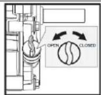
- After the operation the fuel cock must be closed (if available)
- Work attentively, safety conscious and always be fully aware safe stand when working! Caution on uneven work surfaces and work surfaces with a slope!
- Never operate the machine on slopes where the angle is over 15^ !
- Avoid use in wet grass. Risk of slipping!
- Regular breaks reduce the security risk to loss of control due to fatigue.
■ Walk! Never run with the machine
- Be especially careful when you turn the machine or move backwards!
- Never use the machine on soft ground. Risk of tipping!
Take especially care, if the ground contains many stones or roots. An unattended stalling of the drill might easily cause an accident
- Use personal safety equipment: ear protectors, safety gloves in EN 388, class 3111, safety shoes S1, safety goggles or face protection when working with the machine!
- Never operate the machine without or with soft shoes!
- Do not operate in an enclosed or confined areas.
- Exhaust contains poisonous carbon monoxide. The exposure can cause unconsciousness and death.
- If the fuel tank has to be emptied it must be done outdoors. Keep the drained fuel in a specially designated container or dispose of carefully
- Never leave the machine running unattended! Before leaving the working area switch the machine off and wait until the machine stops.
- Switch off the machine before maintenance or adjustment.
- Never remove the fuel tank cap when the engine is running or hot. Switch of the engine and remove the ignition key (if is available):
■ Before check, clean or work on the machine
■ Before refueling
■ Always if you leave the machine
11.3 Remaining risk factors

WARNING
It is important to ensure that each machine has remaining risks.
In the execution of all work (even the simplest) greatest attention is required. A safe working depends on you!
Even if the machine is used as required it is still impossible to eliminate certain residual risk factors totally. The following hazards may arise in connection with the machine's construction and design:
- Risk of noise:
Working for a long time can damage your hearing if you do not use a very good hearing protection.
• Risks of working area:
Keep attention for stones and other things that can be thrown around by the machine.
- Risk to the hands or fingers:
Risk of crushing: Operate the machine firmly with both hands. When tilting the dump box keep extreme caution.
Risk of burns: Access while it is working in the mowing apparatus. After the operation, the machine must cool down. Otherwise, there is an acute risk of scalding!
- Risk of fire and explosion:
Gasoline is highly flammable and explosive under certain conditions.
NEVER refuel fuel or engine oil while the machine is in operation or is hot.
When refueling and at places where fuel is stored not smoke or allow open flames or sparks.
Do not overfill the fuel tank and avoid the spillage of gasoline during refueling. If fuel is spilled make sure the area is completely dry and cleaned before starting the engine.
Make sure that the filler cap is tightly closed again after refueling safely.
- Chemical risks:
Never use or refuel a gasoline or diesel engine in a closed area without adequate ventilation.
Carbon monoxide emissions from the internal drive units of the engine can cause in confined spaces through inhalation health effects and death. Therefore use the machine only in well-ventilated rooms or outdoors in operation.
Liquid fuels can cause serious damage on the skin and the environment.
- Vibration:
The declared vibration emission value has been for a standardized test is measured and can be used to compare one tool with another electric are.
The declared vibration emission value may also be used for a preliminary assessment of exposure. Warning:
Emission level of vibration can be different from the specified value during the actual use of the electric tool, depending on the manner in which the power tool is used. When you feel uncomfortable or notice discoloration of skin on your hands during the use of the machine, stop working immediately. Observe sufficient break times to rest. Failure to have sufficient break times may result in a hand-arm vibration syndrome.
The extent of exposure depending on the type of work or machine use should be estimated and appropriate breaks taken. In this way, the extent of exposure can be considerably reduced over the entire work time. Minimize the risk caused by vibrations. Maintain this machine according to the instructions in the manual.
These risk factors can be minimized through obeying all security and operation instructions, proper machine maintenance, proficient and appropriate operation by persons with technical knowledge and experience.
In spite of all safety is and remains her healthy common sense and their corresponding technical qualification / training for use of the machines most important safety factor!!
12 ASSEMBLY
Please check the product contents immediately after receipt for any eventual transport damage or missing parts. Claims from transport damage or missing parts must be placed immediately after initial machine receipt and unpacking before putting the machine into operation. Please understand that later claims cannot be accepted anymore.
12.1 Assembly

natural_image
Technical line drawing of a four-wheeled robotic vehicle with visible wheels and mounting components (no text or symbols)
A Wheels:
Mount the wheels and fasten them with nuts.
B Handle frame:
Mount the handle frame assembly to the chassis and secure it with M10X25 bolts, washers and nuts at the front and M10X45 bolts, washers and nuts at the rear.
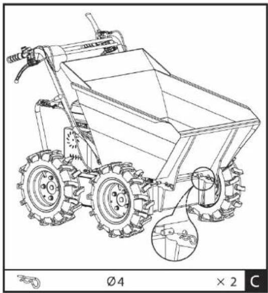
C Dump box:
Install the dump box and fasten the front with two ∅4 R-clips.
natural_image
Line drawing of a two-wheeled agricultural harvester with visible gears and a handle (no text or symbols)13 OPERATION
Device to be operated in a perfect state only. Inspect the device visually every time it is to be used. Check in particular the safety equipment, controls and screwed connection for damage and if tightened properly. Replace any damaged parts before operating the device.
13.1 Operation instructions

NOTICE
• Disengage clutch lever before starting the engine
• Always hold the unit with both hands when operating.
- Do not rapidly accelerate, turn sharply or stop.
• Do not overload the machine capacity
• Always make certain that the weight is evenly balanced
• Always move in directions parallel with the slope (up or down).
• Change the gears only when the machine stands still!
• To avoid danger, do not shift gears on slopes
• Attention: While tipping the centre of gravity will change suddenly!
• Do not tipping on soft ground
13.2 Functions of components
1 Engine switch: The engine switch must be in the ON position for the engine to run.
Turning the engine switch to the OFF position stops the engine.
2 Throttle control: Controls engine speed. Put the throttle control on low speed(L) or high speed(H)
3 Right steering lever: Operate the lever to turn right
4 Clutch control lever: Squeeze the lever, clutch engaged. Release the lever, clutch disengaged
5 Left steering lever: Operate the lever to turn left
7 Gear selection lever: Controls forward (3x) or reverse (1x) movements of the machine.
8 Tipping handle: Controls the tipping of the dump box (manual!)
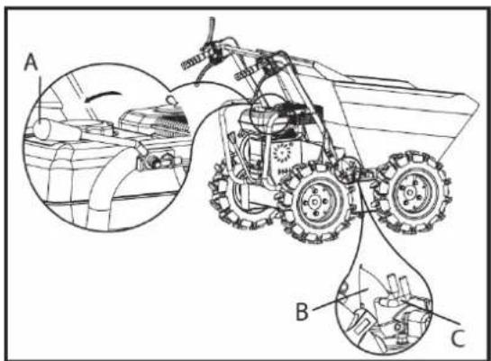
-
Swing tipping handle A in the direction of the arrow to release limiter B out of hook C. The dump box will be released.
-
Tipping by hand

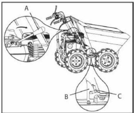
- After tipping the load, swing handle A back to reset limiter B into hook C, which will lock the dump box.
Before start operating, check the dump box to make sure it is locked (B, C)!
13.3 Start up
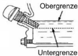
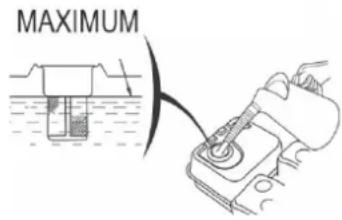
13.3.1 Checking the engine oil level

WARNING
ATTENTION! For transport motor oil has been drained. Fill up with 4-stroke quality motor oil before first operation! Failure to do so will result in permanent motor damage and void guarantee!

NOTICE
A too low oil level will cause damage to the engine and shorten the service life of the machine. Therefore, check the motor oil level before every start and if necessary fill up with oil.

natural_image
Technical line drawing of a mechanical assembly with a connector (no text or symbols)
B32 Refuel
WARNING
Use only unleaded fuel with min. 95 octane or higher
Never use 2-stroke mixture of diesel! DAMAGE OF ENGINE
- Refuelling only outdoors!
- Before removing the filler cap, turn the engine off and let it cool machine
- Clean the fuel filler cap area
- Remove the filler cap carefully
- Fill in fuel
- Fuel tank capacity: 3,6 l. Fill tank only up to 1,5 cm below the rim of the filler neck, so that the fuel has place for expansion.
- Replace and tighten the filler cap
- Wipe any fuel residues and wait until it evaporates
13.4 Operation
T341 Start Engine
Start the engine, if you have your wheeled dumper mounted correctly:
- Set the gear selection lever (7) to the neutral position.
- Move the choke lever on the machine to the full choke position.
- Turn engine switch to "ON".
- Pull the starter rope several times so that the carburettor is filled with gasoline.
- Pull the starter handle, pull-out until resistance is felt. Let the rope rewind slowly across and then move expeditiously.
- Run the pull-starter handle slowly to the rope guide back as soon as the engine starts.
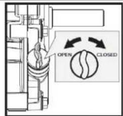
- Set the choke lever after a few seconds of engine run position "OPEN"
To start the engine is warm the choke lever is not to be operated.
- When the engine is warmed up, place the gear lever (7) (forward / reverse) in the desired position. If the desired gear can not load, press the clutch lever short and repeat the process. After inserting the gear lever Push the clutch lever and the mini transporter begins to drive. Drag to adjust the throttle lever to the speed accordingly.
- With the steering arm on the handles and can be easily controlled. To drive in the desired direction each use the right or left steering lever.
T342 Idle speed
Throttle lever to the "SLOW" (SLOWLY) take to protect the motor if no work is done.
Downshifting the engine to idle prolongs the life of engine reduces fuel consumption and the noise level of the machine.
B43 Stop the engine
To stop the engine, release the clutch lever and turn the switch on the motor to the "OFF" position. Under normal conditions, proceed as follows.
a. Move the throttle lever to the SLOW position.
b. Allow engine to idle for 1-2 minutes.
c. Turn engine switch to OFF "OFF".
d. Turn the fuel valve lever to OFF.
ATTENTION: Not move the choke lever to stop the engine to CHOKE. Risk of reignition or damage to the engine!

NOTES
- The steering characteristics change proportional to the speed driven and the laden weight. The lightly loaded machine can be steered with lighter lever operation. With greater loading of the steering lever to control with higher pressure.
- The highest loadings of mini handling is according to the floor on which the machine is used to adjust.
It is therefore recommended to drive on difficult tracks in a low gear and with caution. In such situations, the machine to be driven over the entire range in a low gear. - Avoid sharp turns and frequent changes of direction when driving on the road, especially on rough, tough terrain, which has many sharp, uneven areas, causing high friction.
Although the unit has 4-wheel traction, please remember, to be careful when working under adverse weather conditions (ice, rain and snow) or on soils where the mini-dumper could be unstable. - When the clutch lever is released, the machine is automatically braked and stops.
If the machine is stopped on steep slopes, one of the wheels must be secured with a wedge.
14 MAINTENANCE

ATTENTION
No cleaning, upkeep, checks or maintenance when machine is running Shut off the machine and let it cool down before start servicing!
The machine does not require intense maintenance. However, to ensure a long lifespan, we strongly recommend following the upkeep and maintenance plan.
Repairs must be carried out by specialists! Use original ZIPPER parts only!
NOTICE
Only a properly maintained equipment may be a satisfactory tool. Care and maintenance deficiencies can cause unpredictable accidents and injuries.
Repairs should be performed only by authorized service centers.
Improper operation may damage the equipment or endanger your safety.
14.1 Maintenance plan
| Controls for the maintenance of the machine | |
| Loose or lost screws, nuts, bolts | Regularly prior to each operation |
| Damage of any part of the machine | Regularly prior to each operation |
| Fuel tank of tightness Regularly prior to each operation | |
| Tires checking Regularly prior to each operation | |
| Machine cleaning | Regularly after operation |
| Cleaning spark plug | Every 25 working hours |
| Cleaning air filter | Every 20-30 working hours |
| Oil level checking Every 50 working hours | |
14.2 Cleaning
Clean the machine and the working attachment from soil, dust, grass, chips, and small twigs, etc.
NOTICE
The use of solvents, harsh chemicals or abrasive cleaners leads to damage to the machine!
Therefore: When cleaning, use only mild detergent
The use of high pressure cleaners is not recommended. It shortens the service life and reduces the operational integrity. (Water can get into the gear!)
Impregnate bare surfaces of the machine against corrosion (e.g., anti-rust WD40)
14.3 Engine
Information about engine maintenance you can find in operation manual of the engine manufacturer!
1431 Engine oil exchange
The engine oil change would be explicitly mentioned here in order to be included in the machine operating manual. Oil change interval after the first 20h or 1 month after commissioning and then every 100h or 1x per year.
NOTICE


Waste oils are toxic and must not be released into the environment! Contact your local authorities for information on proper disposal.
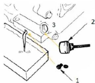
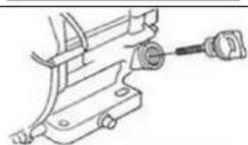
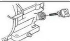
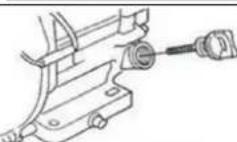
- Remove the oil drain plug (1) from the engine.
- Open the oil tank cap (2). Collect the draining oil in a collection container and dispose of it properly.
- Retighten the oil drain plug after draining.
- Fill in fresh oil through the filling opening (3) (see section Checking the engine oil level).
- Use only high quality engine oil, e.g: SAE30, 15W40 or similar!

NOTICE
Drain the used oil when the engine is warm. Warm oil drains quickly and completely.
14.4 Clutch
As clutch wears out, the same lever could have a wider opening, being so uneasy to use. To enable proper operation, the clutch cable must be adjusted:

- Loosen the jam nut (1) by turning it counter clockwise with 10 mm wrench.
- The clutch lever is set to the original position with the adjusting nut (2).
- Then retighten the lock nut (1).
14.5 Steering
If you have difficulty steering the unit, you will need to adjust the steering levers with the special adjusters.
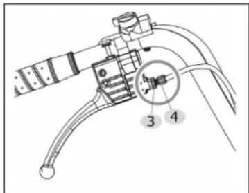
- Loosen the jam nut (3) by turning it counter clockwise with 10 mm wrench.
- Unscrew the adjust nut (4) to eliminate the play in the cable, which can occur after initial use or normal wear. Be very careful not to unscrew the adjust nut too much because this can create another problem: the loss of traction.
- Then retighten the lock nut (3).
If the above adjustment does not create enough cable tension, follow the steps below:

- Loosen the jam nut (5) by turning it counter clockwise with 10 mm wrench.
- Unscrew the adjustment nut (6) to eliminate the play in the cable. (do not to unscrew the adjust nut too much because this can create another problem: the loss of traction).
- Retighten the lock nut (5).
14.6 Tires
Check the pressure of tires periodically to make sure they are properly inflated.
Recommended pressure is: 2,1 bar (0,21Mpa)
14.7 Gearbox
14.7.1 Check gearbox oil
The gearbox is pre-lubricated and sealed at the factory. Unless there is evidence of leakage or service has been performed on the gearbox, no additional lubricate should be required until 50 hours of use.
For future use, check the oil level after every 50 hours of use.


NOTICE
Waste oils are toxic and must not be released into the environment! Contact your local authorities for information on proper disposal.
If you remove the oil level plug and no oil flows out, please add oil and then screw the oil level plug. NOTICE: recommended motor oil: GL-5, GL-6, SAE80W-90. Do not use synthetic oil! If you want to replace oil, place the machine on a level ground. The machine must be stopped and still warm. Unscrew the filter cap and the drain plug. When the oil is drained, replace the drain plug, fill up with fresh oil and then replace the filter cap.
14.8 Storage
If the machine is stored for longer than 30 days:
- Let the machine cool down
- Clean the machine and dry
- Empty Tank and carburetor completely, avoid fuel spillage
- Store in a dry, out of reach of children place, well packaged
14.9 Disposal

Do not dispose the machine, machine components fuel and oil in residual waste. Contact your local authorities for information regarding the available disposal options. When you buy at your local dealer for a replacement unit, the latter is obliged to exchange your old.
15 TROUBLE SHOOTING
| Trouble Possible cause Trouble | ||
| Engine will not start | Incorrect starting sequence | Observe the correct starting sequence |
| Dirty air filter | Clean/replace air filter | |
| No fuel supply | Refuel | |
| Fault in the fuel line | Check the fuel line for kinks or damages | |
| Engine flooded. | Screw off, clean and dry the spark plug. Then pull the cranking rope several times and reinstall the spark plug | |
| Spark plug connector not placed on. | Place on the spark plug con- nector | |
| No ignition spark | Clean/replace spark plugCheck ignition cable | |
| Engine starts and is stalled immedi-ately | Incorrect idle adjustment | Contact customer service |
| Machine works with interruptions | Carburetor incorrectly adjusted | Contact customer service |
| Spark plug fouled | Clean/replace spark plugCheck spark plug connector | |
| Machine does not work with full per-formance | Machine overloaded | Too much pressuresoil too tough |
| Dirty air filter | Clean/replace air filter | |
| Carburetor incorrectly adjusted | Contact customer service | |
| Machine does not run while the engine is running | Gear is not engaged properly | Shift lever in right posi-tion switch |

NOTICE
Should you in necessary repairs not able to properly to perform or you have not the prescribed training for it always attract a workshop to fix the problem.
16 PREFACIO (ES)
Estimado cliente,
natural_image
Technical line drawing of a four-wheeled robotic vehicle with visible wheels and mounting components (no text or symbols)
A - Ruedas:
natural_image
Technical line drawing of a manual tiller with visible gears and a handle, showing mechanical components and assembly (no text or symbols)19 FUNCIONAMIENTO

natural_image
Technical line drawing of a four-wheeled robotic vehicle with visible wheels and mounting components (no text or symbols)
A Kotači:
natural_image
Technical line drawing of a mechanical wheeled cart with visible gears and wheels, showing no text or symbols.25 RAD

Ur Donja granica
natural_image
Diagram showing a mechanical device with a curved arrow pointing to a submerged object (no text or symbols present)- Gorivo točite samo na otvorenom!
- Prije skidanja poklopca spremnika isključite motor i pustite stroj da se ohladi.
- Očistite područje poklopca spremnika.
- Oprezno skinite poklopac spremnika.
- Natočite gorivo.
- Volumen spremnika motora: vidi Tehnički podaci. Spremnik napunite samo do 1,5 cm ispod ruba nastavka za ulijevanje kako bi gorivo imalo prostora za širenje.
- Ponovno zavrnite poklopac spremnika.
- Obrišite eventualne ostatke goriva i pričekajte da pare ishlape.
25.4 Rukovanje
2541 Pokretanje motora
Pokrenite motor ako ste propisno montirali damper s kotačima:
Cher client, chère cliente,
natural_image
Technical line drawing of a four-wheeled robotic vehicle with visible wheels and mounting components (no text or symbols)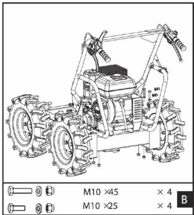
A Roues :
natural_image
Technical line drawing of a mechanical dump truck with visible tire tracks and wheel assembly (no text or symbols)31 FONCTIONNEMENT

natural_image
Technical line drawing of a four-wheeled robotic vehicle with visible wheels and mounting brackets (no text or symbols)
A Točkovi:
natural_image
Technical line drawing of a mechanical dump truck with visible gears and wheel assembly (no text or symbols)37 RAD
Koristite mašinu samo kada je u savršenom stanju. Izvršite vizuelni pregled mašine pre svakog korišćenja. Sigurnosni uređaji i radni elementi moraju vrlo pažljivo da se provere. Proverite jesu li vijčani spojevi oštećeni i zategnuti.
37.1 Uputstva za upotrebu

NAPOMENA
- Povucite polugu za istovar (A) u pravcu rukovaoca i otključajte kontejner za istovar (B, C)
- Nagnite kontejner za istovar napred i istovarite ga rukom

- Prebacite kontejner nazad u početni položaj
- Gurnite polugu za istovar (A) napred i ponovo zaključajte kontejner za istovar (B, C)
37.3 Puštanje u rad
37.3.1 Provera nivoa motornog ulja

UPOZORENJE
PAŽNJA! Motorno ulje ispušteno radi transporta. Pre upotrebe napunite motornim uljem. Ukoliko to ne učinite, može doći do potpunog oštećenja motora i poništenja garancije!

NAPOMENA
Prenizak nivo ulja može oštetiti motor i skratiti životni vek mašine. Stoga pre svakog pokretanja proverite nivo motornog ulja i po potrebi dolijte motorno ulje.


Donja granica
-
Za proveru nivoa motornog ulja, postavite mašinu na sigurnoj, ravnoj površini. Ugasite motor i ostavite mašinu deset minuta kako bi se ulje koje cirkuliše skupilo u koritu ulja.
-
Odvijte mernu šipku za ulje i obrišite je čistom krpom koja ne ostavlja dlačice ili papirnim ubrusom koji ne ostavlja dlačice.
-
Gurnite mernu šipku nazad u otvor koliko god može, ali je nemojte zavrnuti. (Uverite se da je šipka gurnuta do kraja - ponekad se zaglavi.)
-
Ponovno izvucite šipku za merenje ulja i očitajte nivo ulja. Za to postoje dve oznake – vidi sliku levo.
-
Ako je nivo ulja nizak, dolijte preporučeno ulje do gornje ivice (pogledajte tehničke podatke za maksimalnu zapreminu punjenja).
-
Gurnite mernu šipku za ulje nazad i zategnite je.
-
Očistite mašinu od prolivenog ulja.
3732 Punjenje gorivom
UPOZORENJE
- Uklonite zavrtanj za ispuštanje ulja (1) na motoru.
- Otvorite čep rezervoara za ulje (2). Ispušteno ulje sakupite u rezervoar i propisno ga odložite!
- Ponovo zategnite čep za ispuštanje ulja nakon ispuštanja.
- Dolijte sveže ulje kroz otvor za punjenje (3) (pogledajte odeljak Provera nivoa motornog ulja).
Koristite samo motorno ulje visokog kvaliteta, npr.: SAE30, 15W40 ili slično!
NAPOMENA

- Otpustite sigurnosnu maticu (1) okretanjem u smeru suprotnom od kazaljke na satu pomoću ključa od 10 mm.
- Poluga kvačila se pomoću uređaja za podešavanje (2) vraća u prvobitni položaj.
- Zatim pritegnite ponovno kontra maticom (1).
38.5 Upravljanje
Ako je upravljanje kruto, j nj spnj dănjt 3 dădăj njžit Aonč drîsîkənjj npt A pdažižyžanč dsžužl id°
| 1. Otpustite sigurnosnu maticu (3) okretanjem u smeru suprotnom od kazaljke na satu pomoću ključa od 10 mm.2. Otpustite maticu za podešavanje (4) kako biste uklonili opuštenost kabla koja se može pojaviti nakon prve upotrebe ili kod normalnog trošenja. Pazite da ne odvrnete zavrtnje za podešavanje previše jer to može dovesti do drugog problema: gubitka vuče.3. Ponovo zategnite sigurnosnu maticu (3). |
natural_image
Technical line drawing of a four-wheeled robotic vehicle with visible wheels and mounting components (no text or symbols)
„A" Kerekek:
natural_image
Technical line drawing of a small wheeled utility vehicle with visible wheels and a handle, showing mechanical components and a close-up inset (no text or symbols)43 ÜZEMELÉS


(EN) With original ZIPPER spare parts you use parts that are attuned to each other shorten the installation time and elongate your products lifespan.
NOTICE

The installation of other than original spare parts voids the warranty!
So you always have to use original spare parts
Order the spare parts directly on our homepage – category SPARE PARTS or contact our customer service
• via our Homepage – category SERVICE/NEWS - SPARE PARTS REQUEST,
• by e-mail to eg01@zipper-maschinen.at.
Always state the machine type, spare part number and designation. To prevent misunderstandings, we recommend that you add a copy of the spare parts drawing with the spare parts order, on which the required spare parts are clearly marked, especially when not using the online-spare-part catalogue.
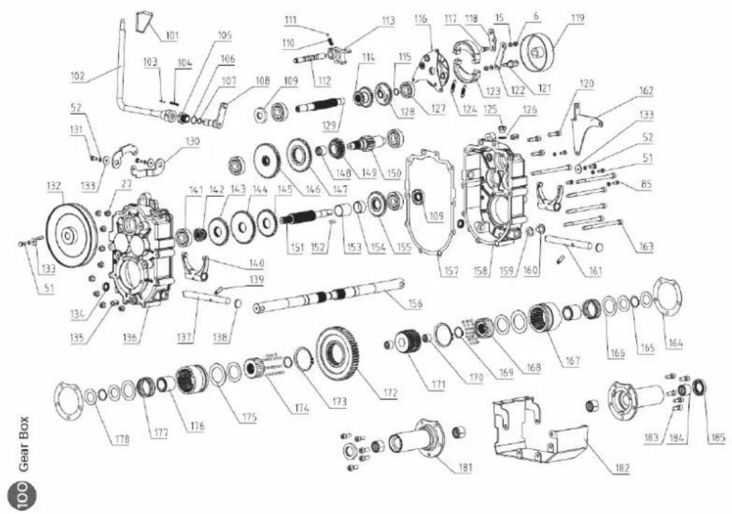
| No. | Description | Qty | No. | Description | Qty |
| 1 | Engine | 1 | 104-1 | Pin 5 x 30 | 1 |
| 2 | Handle Sleeve | 2 | 105 | Orientation nut | 1 |
| 3 | ON/OFF Switch | 1 | 106 | O-Ring 17 x 1,8 | 1 |
| 4 | Throttle Lever | 1 | 107 | O-Ring 11.2 x 1,8 | 1 |
| 5 | Throttle Cable | 1 | 108 | Lever mount bracket | 1 |
| 6 | Locknut M6 | 12 | 109 | Seal FB17 x 47 x 7 | 1 |
| 7 | Clutch Control Lever | 1 | 110 | Spring | 1 |
| 8 | Bolt M6x20 | 2 | 111 | Steel ball 6 | 1 |
| 9 | Clutch Control Cable | 1 | 112 | Gearshift fork shaft | 1 |
| 10 | Hoop | 2 | 113 | Gearshift fork | 1 |
| 11 | Down Lever | 2 | 114 | Slip duplex pulley | 1 |
| 12 | Right/Left Steering Cable | 2 | 115 | Ciclip 15 | 1 |
| 13 | Box | 1 | 116 | Rivet assembly | 1 |
| 14 | Screw M6x55 | 1 | 117 | Joint bolt | 1 |
| 15 | Washer 6 | 26 | 118 | Plate | 1 |
| 16 | Lock nut M10 | 52 | 119 | Expansion brake cover | 1 |
| 17 | Washer 10 | 63 | 120 | Bolt M8 x30 | 3 |
| 18 | Cable Plate | 1 | 121 | Bolt | 1 |
| 19 | Rocker Lever | 1 | 122 | Brake pull plate | 1 |
| 20 | Dumper Box Cable | 1 | 123 | Brake disc | 2 |
| 21 | Mounting Base for Engine | 1 | 124 | Spring | 2 |
| 22 | Square Neck Bolt | 4 | 125 | Vent-plug | 1 |
| 23 | Pulley Front Cover | 1 | 126 | Gasket | 1 |
| 24 | Pulley Back Cover | 1 | 127 | Bearing 6302 | 1 |
| 25 | bolt M8X16 | 1 | 128 | Pulley | 1 |
| 26 | Spring Washer 8 | 7 | 129 | Shaft I | 1 |
| 27 | Lock Nut M8 | 36 | 130 | Swnig plate | 2 |
| 28 | Washer 8 | 49 | 131 | Bolt M6 x 20 | 2 |
| 29 | Bolt M8X20 | 6 | 132 | Pulley | 1 |
| 30 | Flange Nut M8 | 6 | 133 | Big washer 6 | 4 |
| 31 | Bolt M8X40 | 4 | 134 | Seal fb16 x 22 x 4 | 2 |
| 32 | Bolt M8X60 | 1 | 135 | Pin 12 x 20 | 2 |
| 33 | Gear Box | 1 | 136 | Gear box case (R) | 1 |
| 34 | Bush | 1 | 137 | clutch fork shaft (R) | 1 |
| 35 | Flange Nut M10 | 3 | 138 | Plug | 2 |
| 36 | Plain washers-large | 2 | 139 | Screw M8 x 25 | 2 |
| 37 | Belt Pulley | 1 | 140 | Clutch fork shaft | 2 |
| 38 | Flat Key B5x40 | 1 | 141 | Bearing 6303 | 5 |
| 39 | Belt Shaft | 1 | 142 | Gear II-5 | 1 |
| 40 | Circlip 8 | 1 | 143 | Gear II-4 | 1 |
| 41 | Rockshaft | 1 | 144 | Gear II-3 | 1 |
| 42 | Cable Fixed Pin 1 | 2 | 145 | Gear II-2 | 1 |
| 43 | Thin Nut M10 | 3 | 146 | Gear III-4 | 1 |
| 44 | Taper Knob | 1 | 147 | Gear III-3 | 1 |
| 45 | Bolt M8X25 | 5 | 148 | Gear III-3 Bush | 1 |
| 46 | Fixed Bracket | 1 | 149 | Gear III-2 | 1 |
| 47 | Bolt M10X45 | 4 | 150 | Gear III | 1 |
| 48 | Bolt M10X25 | 12 | 151 | Shaft li | 1 |
| 49 | Handle Frame Assembly | 1 | 152 | Key C5 x 20 | 2 |
| 50 | Cover Weldment | 2 | 153 | Bush 1 | 1 |
| 51 | Bolt M6X16 | 24 | 154 | Bush 2 | 1 |
| 52 | Spring Washer 6 | 18 | 155 | Gear II-1 | 1 |
| 53 | Pin 4 | 2 | 156-1 | Output shaft | 2 |
| 54 | Chain Guide Posts | 2 | 157 | Output gear bush gasket | 1 |
| 55 | Bolt M8X70 | 2 | 158 | Gear box case (L) | 1 |
| 56 | Screw M8X25 rubber pad screw | 2 | 159 | Washer groupware 14 | 1 |
| 57 | Chain 2 | 2 | 160 | Plug m14 x 1.5 | 1 |
| 58 | Chain 1 | 2 | 161 | Clutch fork shaft (l) | 1 |
| 59-1 | Brake cable | 1 | 162 | Cable connection plate weldment | 1 |
| 60 | B-Belt | 1 | 163 | Bolt M8 x 130 | 6 |
| 61 | Belt Guide Weldment | 1 | 164 | Output gear bush gaske | 2 |
| 62 | Screw M6 x 16 | 6 | 165 | Ciclip 25 | 2 |
| 63 | Oil Nipple M6 | 1 | 166 | Spring gasket | 4 |
| 64 | Tensioner Pulley Bracket | 1 | 167 | Clutch bush | 2 |
| 65 | Circlip 15 | 1 | 168 | Joint bush | 2 |
| 66 | Circlip 35 | 1 | 169 | Ciclip 26 | 2 |
| 67 | Bearing 6202 | 2 | 170 | Joint bush composite bushing | 2 |
| 68 | Tensioner Pulley | 1 | 171 | Joint bush | 1 |
| 69 | Bolt M6X25 | 1 | 172 | Output gear | 1 |
| 70 | Bolt M12X60 | 1 | 173 | Ciclip 58 | 2 |
| 71 | Flange Nut M12 | 1 | 174 | Steel ball 5 | 42 |
| 72-1 | Limiting Plate | 1 | 175 | Spring gasket | 2 |
| 73-1 | Chassis | 1 | 176 | Spring guidebush | 2 |
| 74 | Fender | 4 | 177 | Clutch spring | 2 |
| 75 | Rear Chain wheel | 2 | 178 | Gasket 1 | 4 |
| 76 | Bearing 205 | 4 | 179 | Screw M10x50 | 2 |
| 77 | Bush 2 | 2 | 180 | Driving wheel | 2 |
| 78 | Flat Key A8X60 | 2 | 181-1 | Output shaft house | 2 |
| 79-1 | Rear Rim | 2 | 182 | Guard cover | 1 |
| 80 | Flat Key A10X60 | 2 | 183 | Bold M8x20 | 10 |
| 81-1 | Left Wheel | 2 | 184 | Output shaft composite bushing | 4 |
| 82-1 | Front Rim | 2 | 185 | Seal FB42x25x7 | 2 |
| 83 | Bush 1 | 4 | 186 | Right wheel | 2 |
| 84 | Bearing 305 | 4 | 187 | Cable stopper (short) | 3 |
| 85 | Front Rim | 2 | 188 | Washer 48x12.5x4 | 2 |
| 86 | Washer 40x13.5x4 | 4 | 189 | Screw M6x16 | 2 |
| 87 | Spring Washer 12 | 20 | 190 | Spring washer 10 | 1 |
| 88 | Bolt M12X20 | 4 | 191 | Bold M10x16 | 1 |
| 89 | Small Connecting Plate | 2 | 192 | Fixed Plate | 1 |
| 90 | Wheel Axle Press Board | 2 | 193 | Ciclip 22 | 1 |
| 91 | Spring | 2 | 194 | Support sleeve | 1 |
| 93 | Bolt M8X175 | 6 | 195 | Nut M6 | 1 |
| 94-1 | Bolt M10X25 | 12 | 196 | Pin 3 x 30 | 1 |
| 95 | Bolt M12X30 | 16 | 197 | Lock nut M12 | 17 |
| 96 | Washer 12 | 16 | 198 | Thin Nut M6 | 1 |
| 97 | Bolt M10X70 | 1 | |||
| 98 | Screw M6X20 | 4 | |||
| 99 | Chain pad (right) | 1 | |||
| 100 | Chain pad (left) | 1 | |||
| 101 | Lever knod | 1 | |||
| 102 | Lever | 1 |
Company ZIPPER Maschinen GmbH grants for mechanical and electrical components a warranty period of 2 years for amateur use; and warranty period of 1 year for professional use, starting with the purchase of the final consumer. In case of defects during this period, which are not excluded by paragraph 3, ZIPPER will repair or replace the machine at its own discretion.
2.) Report:
In order to check the legitimacy of warranty claims, the final consumer must contact his dealer. The dealer has to report in written form the occurred defect to ZIPPER. If the warranty claim is legitimate, ZIPPER will pick up the defective machine from the dealer. Returned shippings by dealers which have not been coordinated with ZIPPER, will not be accepted and refused.
3.) Regulations:
a) Warranty claims will only be accepted, when a copy of the original invoice or cash voucher from the trading partner of ZIPPER is enclosed to the machine. The warranty claim expires if the accessories belonging to the machine are missing.
b) The warranty does not include free checking, maintenance, inspection or service works on the machine. Defects due to incorrect usage of the final consumer or his dealer will not be accepted as warranty claims either. Some examples: usage of wrong fuel, frost damages in water tanks, leaving fuel in the tank during the winter, etc.
c) Defects on wear parts are excluded, e.g. carbon brushes, collection bags, knives, cylinders, cutting blades, clutches, sealings, wheels, saw blades, splitting crosses, riving knives, riving knife extensions, hydraulic oils, oil/air/fuel filters, chains, spark plugs, sliding blocks, etc.
d) Also excluded are damages on the machine caused by incorrect or inappropriate usage, if it was used for a purpose which the machine is not supposed to, ignoring the user manual, force majeure, repairs or technical manipulations by not authorized workshops or by the customer himself, usage of non-original ZIPPER spare parts or accessories.
e) After inspection by our qualified personnel, resulted costs (like freight charges) and expenses for not legitimated warranty claims will be charged to the final customer or dealer.
f) In case of defective machines outside the warranty period, we will only repair after advance payment or dealer's invoice according to the cost estimate (incl. freight costs) of ZIPPER.
g) Warranty claims can only be granted for customers of an authorized ZIPPER dealer who directly purchased the machine from ZIPPER. These claims are not transferable in case of multiple sales of the machine.
4.) Claims for compensation and other liabilities:
The liability of company ZIPPER is limited to the value of goods in all cases. Claims for compensation because of poor performance, lacks, damages or loss of earnings due to defects during the warranty period will not be accepted. ZIPPER insists on its right to subsequent improvement of the machine.
SERVICE
After Guarantee and warranty expiration specialist repair shops can perform maintenance and repair jobs. But we are still at your service as well with spare parts and/or product service. Place your spare part/repair service cost inquiry by
- Mail to service@zipper-maschinen.at.
- Or use the online complaint order formula provided on our homepage – category service/news.
50 GARANTÍA Y SERVICIO (ES)
1.) Garantía:
We monitor the quality of our delivered products in the frame of a Quality Management policy.
Your opinion is essential for further product development and product choice. Please let us know about your:
- Impressions and suggestions for improvement.
- experiences that may be useful for other users and for product design
- Experiences with malfunctions that occur in specific operation modes
We would like to ask you to note down your experiences and observations and send them to us by E-Mail or by post


- INHALT/INDEX
- MAINTENANCE 34
- TROUBLE SHOOTING 37
- PREFACIO (ES) 38
- SEGURIDAD 39
- Lieferumfang/Delivery content/Entrega de la máquina/Opseg isporuke / Contenu de la livraison / Obim isporuke / Szállítási terjedelem
- VORWORT (DE)
- A Räder:
- BETRIEB
- Please follow the security instructions!
- Copyright law
- Customer Support
- WARNING
- Ambient conditions
- Prohibited use
- Security instructions
- Remaining risk factors
- - Risk of noise:
- • Risks of working area:
- - Risk to the hands or fingers:
- - Risk of fire and explosion:
- - Chemical risks:
- - Vibration:
- ASSEMBLY
- A Wheels:
- B Handle frame:
- C Dump box:
- OPERATION
- Operation instructions
- NOTICE
- Functions of components
- Start up
- Checking the engine oil level
- B32 Refuel
- Use only unleaded fuel with min. 95 octane or higher
- Never use 2-stroke mixture of diesel! DAMAGE OF ENGINE
- Operation
- T341 Start Engine
- Start the engine, if you have your wheeled dumper mounted correctly:
- To start the engine is warm the choke lever is not to be operated.
- T342 Idle speed
- B43 Stop the engine
- NOTES
- MAINTENANCE
- ATTENTION
- Maintenance plan
- Cleaning
- The use of solvents, harsh chemicals or abrasive cleaners leads to damage to the machine!
- Engine
- Engine oil exchange
- Clutch
- Steering
- Tires
- Gearbox
- Check gearbox oil
- Storage
- Disposal
- PREFACIO (ES)
- Estimado cliente,
- A - Ruedas:
- FUNCIONAMIENTO
- A Kotači:
- RAD
- Rukovanje
- Pokretanje motora
- Pokrenite motor ako ste propisno montirali damper s kotačima:
- Cher client, chère cliente,
- A Roues :
- FONCTIONNEMENT
- A Točkovi:
- RAD
- Uputstva za upotrebu
- NAPOMENA
- Puštanje u rad
- Provera nivoa motornog ulja
- UPOZORENJE
- Punjenje gorivom
- Upravljanje
- „A" Kerekek:
- ÜZEMELÉS
- The installation of other than original spare parts voids the warranty!
- 2.) Report:
- 3.) Regulations:
- 4.) Claims for compensation and other liabilities:
- SERVICE
- GARANTÍA Y SERVICIO (ES)
- 1.) Garantía:
Brand : Zipper
Model : ZIRD300
Category : Construction Equipment