
ZIMD500HST - Tractor Zipper - Free user manual and instructions
Find the device manual for free ZIMD500HST Zipper in PDF.
| Product Type | Mini crawler dumper |
| Brand | Zipper |
| Model | ZIMD500HST |
| Engine | 4-stroke gasoline, unleaded RON 95 |
| Recommended Fuel | Unleaded gasoline RON 95 |
| Recommended Engine Oil | SAE30, 15W40 or similar |
| Hydraulic Oil | HLP46, capacity: 3.5 L |
| Transmission Oil | GL-5, GL-6, SAE80W-90 |
| Maximum Lateral Inclination | 26° |
| Maximum Longitudinal Inclination | 30° |
| Speeds | 3 forward, 1 reverse |
| Starting | Recoil starter |
| Steering System | Left/right steering levers |
| Dump Bucket | Hydraulic, with dump lever |
| Engine Maintenance | Oil change every 100 h or 1 year |
| Air Filter Maintenance | Clean every 50 h |
| Safety | Engine shut-off switch, automatic brake when disengaging |
| Intended Use | Loading, unloading, transport in gardening and landscaping |
| Warranty | 2 years non-commercial use, 1 year commercial |
Frequently Asked Questions - ZIMD500HST Zipper
User questions about ZIMD500HST Zipper
0 question about this device. Answer the ones you know or ask your own.
Ask a new question about this device
Download the instructions for your Tractor in PDF format for free! Find your manual ZIMD500HST - Zipper and take your electronic device back in hand. On this page are published all the documents necessary for the use of your device. ZIMD500HST by Zipper.
USER MANUAL ZIMD500HST Zipper
natural_image
Green ZIPPER ZI-MD500HST tracked bulldozer with black metal blade (no visible text or symbols on the device itself)
ZI-MD500HST
EAN: 9120039233291
CE
11.1 Intended use of the machine....31
11.1.1 Prohibited applications / Dangerous misuse....31
11.2 Safety instructions 31
11.3 Remaining risk factors 33
12 ASSEMBLY....33
12.1 Assembly....34
12.1.1 ZI-MD500HST....34
13 OPERATION 35
13.1 Operating instructions....35
13.2 Function of components 35
13.3 Start up 36
13.3.1 Fill in engine oil....36
13.3.2 Refuel 36
13.3.3 Check hydraulic oil 37
13.4 Operation....37
13.4.1 Start Engine 37
13.4.2 Idle speed 37
13.4.3 Stop the engine....37
13.4.4 Dump box lifting and lowering ZI-MD500HST 38
14 MAINTENANCE....38
14.1 Maintenance plan 39
14.2 Cleaning 39
14.3 Engine 39
14.3.1 Engine oil exchange....39
14.3.2 Check hydraulic oil 40
14.4 Gearbox....40
14.4.1 Check gearbox oil....40
14.5 Clutch....41
14.6 Steering 41
14.7 Tracks....42
14.7.1 Tightening....42
14.72 Replacing tracks 42
14.8 Air filter....43
14.9 Storage 43
14.10 Disposal 43
15 TROUBLESHOOTING....44
16 PRÓLOGO (ES) 45
17 SEGURIDAD 46
26.4 Transmission....72
EN CE-Conformal! - This product complies with the EC-directives.
EN READ THE MANUAL! Read the user and maintenance carefully and get familiar with the controls in order to use the machine correctly and to avoid injuries and machine defects.
EN ATTENTION! Ignoring the safety signs and warnings applied on the machine as well as ignoring the security and operating instructions can cause serious injuries and even lead to death.
EN Stop before any break and engine maintenance!
EN Wear protective equipment!
EN It is forbidden to remove the protection devices and safety devices.
EN Gasoline and oil are highly flammable and explosive! Do not smoke or have open flames near the machine!
EN Burn hazard! Keep away from hot parts on the machine!
EN Solid Objects can be thrown away!
EN Keep your hands and feet clear from all rotating parts!
EN Keep safe distance!
EN Only for working outside! The exhaust fumes are dangerous, containing carbon monoxide.
EN Tipping hazard! Do not operate on slopes with angle over 26^ or tip loading at an inclined position.
EN ATTENTION! Fill up with 4-stroke quality motor oil before first operation! Failure to do so will result in permanent engine damage and void guarantee.
| # | Beschreibung / Description /Description / Opis / Opis / Leírás | # | Beschreibung / Description /Description / Opis / Opis / Leírás |
| 1 | Motorschalter / engine switch / Guardamotor /Interrupteur moteur / Prekidač motora / Prekidačmotora / Motorkapcsoló | 6 | Kippbehälter / dump box / Volquete /Benne basculante / Spremnik za istovar /Kontejner za istovar / Billenőtartály |
| 2 | Gashebel / throttle control / Acelerador /Poignée des gaz / Poluga gasa / Poluga gasa /Gázszabályozó kar | 7 | Schalthebel / gear selection lever /Palanca de cambio / Levier d'embrayage /Ručica mjenjača / Ručica menjača /Kapcsolókar |
| 3 | Rechter Lenkhebel / right steering lever /Palanca derecha de dirección /Poignée de direction côté droit / Desna polugaupravljača / Desna poluga upravljača / Jobb oldalikormánykar | 8 | Kipphebel / tipping handle /Palanca de vuelco / Levier de basculement /Poluga za istovar / Poluga za istovar /Billentőkar |
| 4 | Kupplungshebel / clutch control lever /Palanca de embrague / Levier d'accouplement /Poluga spojke / Poluga kvačila / Kuplungkar | 9 | Antriebskette / track / Cadena motriz /Chaîne d'entraînement / Pogonski lanac /Pogonski lanac / Hajtólánc |
| 5 | Linker Lenkhebel / left steering lever /Palanca izquierda de dirección /Poignée de direction côté gauche / Lijeva polugaupravljača / Leva poluga upravljača / Bal oldalikormánykar | 10 | Getriebe / gearbox / Engranaje / Transmission /Prijenosnik / Menjač / Hajtómů |
3.2 Lieferumfang / delivery content / Volumen de suministro / Contenu de la livraison / Opseg isporuke / Obim isporuke / Szállítási terjedelem

natural_image
Line drawing of a tracked robotic vehicle with a cab and wheels (no text or symbols)

natural_image
Technical line drawing of a curved metal frame with mounting feet and a small inset image showing two objects (no text or symbols)| Beschreibung / Description / Description / Opis / Opis / Leírás | Beschreibung / Description / Description / Opis / Opis / Leírás | ||
| 1 | Hauptrahmen mit Lenkgestell u. Motor / Main frame with motor, handlebar assy / Bastidor principal con marco de dirección y motor / Châssis principales avec train de direction et moteur / Glavni okvir s okvirom upravljača i motorom / Glavni okvir s okvirom upravljača i motorom / Fő keret forgóállvánnyal és motorral | 10 | Kleinteile / hardware / Piezas pequeñas / Petit matériel / Mali dijelovi / Mali delovi / Apró alkatrészek |
| 9 | Betriebsanleitung / manual / Instrucciones de servicio / Mode d'emploi / Upute za uporabu / Uputstvo za upotrebu / Használati útmutató | 11 | Schneeschild + Kleinteile / Snow blade + hardware / Escudo quitanieves + piezas pequeñas / Chasse-neige + petites pièces / Snježni plug + sitni dijelovi / Snežni plug + sitni delovi / Hótolólap és apró alkatrészek |
3.3 Technische Daten / technical data / Datos técnicos / Données techniques / Tehnički podaci / Tehnički podaci / Můszaki adatok
(DE) Hinweis Geräuschangaben: Die angegebenen Werte sind Emissionswerte und müssen damit nicht zugleich auch sichere Arbeitsplatzwerte darstellen. Obwohl es eine Korrelation zwischen Emissions- und Immissionspegeln gibt, kann daraus nicht zuverlässig abgeleitet werden, ob zusätzliche Vorsichtsmaßnahmen notwendig sind oder nicht. Faktoren, welche den am Arbeitsplatz tatsächlich vorhandenen Immissionspegel beeinflussen, beinhalten die Eigenart des Arbeitsraumes und andere Geräuschquellen, d. h. die Zahl der Maschinen und anderer benachbarter Arbeitsvorgänge. Die zulässigen Arbeitsplatzwerte können ebenso von Land zu Land variieren. Diese Information soll jedoch den Anwender befähigen, eine bessere Abschätzung von Gefährdung und Risiko vorzunehmen.
(EN) Notice noise emission: The values given are emission values and therefore do not have to represent safe workplace values at the same time. Although there is a correlation between emission and immission levels, it cannot be reliably deduced whether additional precautions are necessary or not. Factors influencing the actual immission level at the workplace include the nature of the workspace and other noise sources, i.e. the number of machines and other adjacent operations. The permissible workplace values may also vary from country to country. However, this information should enable the user to make a better assessment of hazard and risk.
(ES) Aviso sobre los valores de ruido: Los valores indicados son valores de emisión y, por lo tanto, no representan necesariamente al mismo tiempo valores seguros en el lugar de trabajo. Aunque hay una correlación entre los niveles de emisión y los de inmisión, no se puede deducir con certeza si es necesario adoptar medidas de precaución adicionales o no. Entre los factores que influyen en el nivel de inmisión real en el lugar de trabajo, se encuentran la naturaleza del espacio de trabajo y otras fuentes de ruido, es decir, el número de máquinas y otros procesos de trabajo adyacentes. Asimismo, los valores admisibles en el lugar de trabajo pueden variar de un país a otro. No obstante, esta información debe capacitar al usuario a evaluar mejor los peligros y los riesgos.
(FR) Avis Données sur le bruit: Les valeurs indiquées sont des valeurs d'émission et ne représentent donc pas nécessairement des valeurs de sécurité sur le lieu de travail. Bien qu'il existe une corrélation entre les niveaux d'émission et d'immission, il est impossible de déduire de manière fiable si des mesures de précaution supplémentaires sont nécessaires ou non. Les facteurs influençant le niveau d'immission réellement présent sur le lieu de travail comprennent les caractéristiques de la salle de travail et d'autres sources de bruit, c'est-à-dire le nombre de machines et d'autres processus de travail adjacents. Les valeurs autorisées sur le lieu de travail peuvent également varier d'un pays à l'autre. Toutefois, ces informations devraient permettre à l'utilisateur de mieux évaluer le danger et le risque.
(HR) Obavijest o emisiji buke: Navedene vrijednosti su vrijednosti emisije i stoga ne moraju istovremeno predstavljati vrijednosti sigurnog radnog mjesta. Iako postoji korelacija između razine emisije i imisije, ne može se pouzdano zaključiti jesu li potrebne dodatne mjere opreza ili ne. Čimbenici koji utječu na stvarnu razinu imisije na radnom mjestu uključuju prirodu radnog prostora i druge izvore buke, tj. broj strojeva i drugih susjednih radnih procesa. Također, dopuštene vrijednosti na radnom mjestu se mogu razlikovati od zemlje do zemlje. Međutim, te bi informacije trebale omogućiti korisniku bolju procjenu opasnosti i mogućih rizika.
(SRB) Napomena o emisiji buke: Navedene vrednosti su vrednosti emisije i stoga ne moraju istovremeno da predstavljaju vrednosti sigurnog radnog mesta. Iako postoji korelacija između nivoa emisije i imisije, ne može se pouzdano zaključiti jesu li potrebne dodatne mere opreza ili ne. Faktori koji utiču na stvarni nivo imisije na radnom mestu uključuju prirodu radnog prostora i druge izvore buke, tj. broj mašina i drugih susednih radnih procesa. Takođe, dopuštene vrednosti na radnom mestu se mogu razlikovati od zemlje do zemlje. Međutim, te informacije bi trebale da omoguće korisniku bolju procenu opasnosti i mogućih rizika.
Spezifikation / Specification / Especificación / Spécification / Specifikacija / Specifikacija / Specifikació
(IHU) Zajra vonatkozó adatokkal kapcsolatos megjegyzés: A megadott értékek kibocsátási értékek és nem jelentik egyben a biztonságos munkahelyi értékeket. Habár van összefüggés a kibocsátási és az immissziós szintek között, ebből nem lehet megbízhatóar következtetni arra, hogy szükség van-e további óvintézkedésekre vagy sem. A munkahelyen ténylegesen jelen lévő immissziószintet befolyásoló tényezők közé tartoznak a munkaterület és egyéb zajforrások jellemzői, azaz a munkagépek száma és a szomszédban végzett egyéb munkafolyamatok. A megengedett munkahelyi értékek országonként változhatnak. Ezeknek az információknak azonban lehetővé kell tenniük a felhasználó számára a jobb veszély- és a kockázatértékelést.
| Motor / engine / Motor / Moteur / Motor / Motor / Motor | 1 Zyl. 4-Takt OHV Motor /1 cyl. 4-stroke OHV engine /Motor1 cil. 4-tiempos OHV / #Moteur OHV mono-cylindre quatre temps /1 cilindar 4-taktni OHVmotor /1 cilindar 4-taktni OHV motor /1hengeres négyütemü felül szelepeit motorG300FA |
| Motorleistung / engine power /Potencia del motor / Puissance du moteur / Snaga motora / Snagamotora / Motorteljesítmény | 6,8 kW (bei 3600min-1) |
| Hubraum / displacement / Cilindrada / Cylindrée / Zapremina /Zapremina / Hengerürtartalom | 302 cm ^3 |
| Geschwindigkeit vorwärts / forward speed /Velocidad de avance / Vitesse d'avance / Brzina naprijed / Brzinanapred / Sebesség előre menet | (1) 1,6km/h; (2) 2,9km/h; (3) 3,6km/h |
| Geschwindigkeit rückwärts / reverse speed /Velocidad de retroceso / Vitesse d'arrière / Brzina unatrag / Brzinaunazad / Sebesség hátrafelé | 1,2 km/h |
| Treibstoff / fuel / Combustible / Carburant / Gorivo / Gorivo / Üzemanyag | Benzin unverbleit ROZ 95(oder entsprechendes Gerätebenzin)unleaded fuel with min. 95 octane(corresponding device fuel)Gasolina sin plomo ROZ 95(o la gasolina correspondiente para aparatos)Essence sans plomb ROZ 95 (ou une essence pour machine correspondante) / Bezolovni benzin RON 95 / Bezolovni benzin RON 95 / ROZ 95-ós ólommentes benzin(vagy ennek megfelelő gépbenzin)(ili ekvivalentno gorivo za opremu) |
| Kraftstofftank / fuel tank /Depósito de carburante / Réservoir de carburant / Spremnik za gorivoRezervoar za gorivo / Üzemanyagtartály | 6 l |
| Starter / starter / Arrancador / Démarreur / Starter / Starter / Indító | Reversierstarter / recoilstarter / Arrancador retráctil / Démarreur inverseur /Povratni starter / Povratni starter /Irányváltó gomb |
| Motoröltyp / engine oil type /Tipo de aceite motor / Type d'huile moteur / Vrsta motornog ulja /Vrsta motornog ulja / Motorolaj típusa | 15W40, SAE30, 10W40 |
| Motoröltank / motor oil tank /Cárter / Réservoir d'huile moteur / Spremnik motornog ulja /Rezervoar motornog ulja / Motorolaj tartály | 0,95 l |
| Getriebeölmenge / gear oil tank /Cantidad de aceite para engranajes /Quantité d'huile de transmission / Količina ulja za mjenjače / Količina ulja za menjače / Hajtómúolaj mennyisége | 1,6 l |
| Empfohlenes Getriebeöl / recommended gear oil-type / Aceite para engranajes recomendado / Huile de transmission recommandée /Preporučeno ulje za mjenjače / Preporučeno ulje za menjače /Javasolt hajtómúolaj-típus | 80W90, GL-5, GL-6, SAE80W-90 |
| Hydrauliköltankvolumen / hydraulic oil tank capacity /Volumen del depósito hidráulico /Volume du réservoir d'huile hydraulique / Volumen spremnika hidrauličkog ulja / Volumen rezervoara hidrauličnog ulja / Hidraulikus olaj tartályának úrtartalma | 3,5 l |
| Empfohlenes Hydrauliköl / recommended hydraulic oil-type /Fluido hidráulico recomendado / Huile hydraulique recommandée /Preporučeno hidraulično ulje / Preporučeno hidraulično ulje /Javasolt hidraulikus olaj | HLP 46 |
| Gewicht netto / weight net /Peso neto / Poids net / Težina netto / Težina neto / Nettó tömeg | 271 kg |
| Gewicht netto Schneeschild / weight snow blade net /Peso neto escudo quitanieves / Poids net du chasse-neige / Netotežina snježnog pluga / Neto težina snežnog pluga / A hótolólap nettó tömege | 29,5 kg |
| Max. Zuladungsgewicht / max. loading weight /Peso máx. de carga / Poids de charge maximale / Maksimalna težinakorisnog tereta / Maksimalna težina korisnog tereta / Max. rakodásitömeg | 500 kg |
| Kippbehälter (LxBxH) max. / Dump box size max. /Volquete (LxA×H) máx. / Benne basculante max. (LxlxH) / Spremnik zaistovar (DxŠxV) maks. / Kontejner za istovar (DxŠxV) maks. /Billenótartály (HxSzxM) | 950 x 680 x 465 mm |
| Kippeinrichtung / tilt function /Dispositivo de vuelco / Dispositif de basculement / Uređaj zanaginjanje / Uređaj za naginjanje / Billenöberendezés | Hydraulisch / hydraulic /Sistema hidráulico / Hydraulique /Hidraulički / Hidraulični / Hidraulikus |
| Hand-, Arm-Vibration / vibration handle bar / Barra de vibración / Vibrations main-bras / Vibracije-Šaka-Ruka / Vibracije-Šaka-Ruka / Vibrációs fogantyú | 10,1 m/s2 k: 1,5 m/s2 |
| Garantierter Schall-Leistungspegel / guaranteed sound power level / Nivel de potencia acústica garantizado / Seuil de pression acoustique garanti LWA / Garantirana razina snage zvuka / Garantovani nivo snage zvuka / Garantált hangteljesítményszint | 101 dB(A) |
| Hydraulik Pumpe / hydraulic pump / Bomba hidráulica / Pompe hydraulique / Hidraulična pumpa / Hidraulična pumpa / Hidraulikus szivattyú | 9 l/min |
| Kraftübertragung / transmission / Transmisión / Transmission / Prenosivost snage / Prenosivost snage / Erőátvitel | 3V+1R |
| Kettendimension / track dimension / Dimensiones de la cadena / Dimensions de la chaîne / Dimenzija lanca / Dimenzija lanca / Láncméret | 180/60/38 (Breite/Teilung/Glieder) (width/division/parts) (ancho/división/eslabones) (largeur/pas/maillons) / (širina/nagib/veze) / (širina/nagib/veze) / (Szélesség/osztás/láncszemek) |
| Spurbreite / distance between tracks / Ancho de pista / Largeur de la chaussée / Širina staze / Širina staze / Nyomtáv | 730 mm |
| Maschinenmaße / machine dimension / Medidas de la máquina / Dimensions de la machine / Dimenzije stroja / Dimenzije mašine / Gépméretek | 1605 x 728 x 1040 mm |
4 VORWORT (DE)
natural_image
Technical line drawing of a mechanical clamp or bracket assembly (no text or symbols)
natural_image
Mechanical assembly with labeled parts, no visible text or symbols
natural_image
Close-up of a mechanical assembly with a hand adjusting a component, no visible text or symbols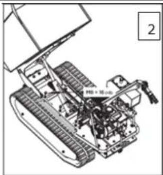
natural_image
Technical line drawing of a tracked robotic vehicle with visible mechanical components and no text or symbols
This manual contains information and important notes for safe commissioning and handling of the ZIPPER mini transporter ZI-MD500HST, hereinafter referred to as "machine".

This manual is part of the machine and must not be removed. Save it for later reference and if you let other people use the machine, add this manual to the machine.
Please read and note the safety instructions!
Due to constant advancements in product design, construction, illustrations and contents may deviate slightly. If you notice any errors, please inform us.
We reserve the right to make technical changes!
Check the goods immediately after receipt and note any complaints on the consignment note when taking over the goods from the deliverer!
Transport damage must be reported to us separately to us within 24 hours.
ZIPPER MASCHINEN GmbH cannot accept any liability for transport damage that has not been reported.
Copyright
© 2020
This documentation is protected by copyright. All rights reserved! In particular, the reprint, translation and extraction of photos and illustrations will be prosecuted.
The place of jurisdiction is the regional court Linz or the court responsible for 4707 Schlüsslberg is valid.
Customer service contact
11.1 Intended use of the machine
The machine must only be used for its intended purpose! Any other use is deemed to be a case of misuse.
To use the machine properly you must also observe and follow all safety regulations, the assembly instructions, operating and maintenance instructions lay down in this manual.
All people who use and service the machine have to be acquainted with this manual and must be informed about the machine's potential hazards.
It is also imperative to observe the accident prevention regulations in force in your area.
The same applies for the general rules of occupational health and safety.
The machine is used for:
Small loading and transportation tasks in landscaping and agriculture.
This machine is not intended for use by persons (including children) with reduced physical, sensory or mental capabilities, or lack of experience and knowledge, unless they have been given supervision or instruction concerning use of the machine by a person responsible for their safety. Never allow children or people unfamiliar with these instructions to use the machine. Supervise children. This will ensure that children do not play with the machine.
NOTE

ZIPPER MASCHINEN assumes no responsibility or warranty for any other use or use beyond this and for any resulting damage to property or injury.
WARNING

- Note the max. load!
- Allowed tilt position in the direction of travel: 30^ (pay attention to the center of gravity and the type of the load!)
- Allowed tilt position transverse to direction of travel: 26^ (pay attention to the center of gravity and the type of the load!)
- It is forbidden to remove the protection devices and safety devices!
- Read also the separately packed operation manual of the engine manufacturer!
HIGHEST RISK OF INJURY!
T1.1 Prohibited applications / Dangerous misuse
- The operation of the machine outside the stated technical limits described in this manual is forbidden.
• Operation of the machine function without any protection devices is forbidden.
• Any manipulation of the machine and parts is forbidden.
• The machine is not approved for transporting passengers.
• The machine is not approved for public traffic! - The use of the machine for any purposes other than described in this user-manual is forbidden.
• It is not allowed to leave the immediate work area during the work is being performed!
11.2 Safety instructions
Missing or non-readable security stickers have to be replaced immediately!
To avoid malfunction, machine defects and injuries, read the following security instructions!
The locally applicable laws and regulations may specify the minimum age of the operator and limit the use of this machine!
• Use the machine only in good enough light to allow a safe operation can be guaranteed.
- In tiredness, decreased concentration or under the influence of alcohol or drugs, the work on the machine is prohibited!
- Unauthorized persons, especially children and not trained personnel must be kept away from the running machine!
- Caution in slippery conditions - slip hazard - risk of injury. When working wear safety shoes. Slides / stumble / traps are a major cause of serious injury.
- The machine must be operated only by trained persons (knowledge and understanding of this manual), which have no limitations of motor skills compared with conventional workers.
• If you pass the machine to third, these instructions must be attached to the machine.
• Before each use, the reliability of the machine is to be checked.
- Do not climb into the dump box.
- Never carry passengers!
- Danger of burns! During the operation flow of hot exhaust gases and engine parts such as the muffler and engine become hot.
- Let the machine cool down before storage.
- After the operation, the machine must cool down. Otherwise there is an imminent risk of burns.
• WARNING: Gasoline is highly flammable!
- Stop the engine before refuelling.
• Smoking and open flames are prohibited during refuelling.
- Do not refuel when the engine and carburettor are still very hot.
• Refuel only outdoors or in a well ventilated area.
- Avoid contact with skin and clothes (fire hazard).
- Check after refuelling tank cap and check for leaks.
• Spilled fuel is to wipe immediately.
- Keep the fuel in suitable containers only.
- Make sure the fuel does not overflow. If the fuel overflows, the engine must not be started. Remove any dirt from the appliance and prevent any attempt at ignition until fuel fumes have evaporated.
- Damaged fuel tank or other tank cap must be replaced immediately.
• After the operation the fuel cock must be closed (if available).
- Work attentively, safety conscious and always be fully aware safe stand when working! Caution on uneven work surfaces and work surfaces with a slope!
- Never operate the machine on slopes where the angle is over 15^ !
- Avoid use in wet grass. Risk of slipping!
• Regular breaks reduce the security risk to loss of control due to fatigue.
- Be especially careful when you turn the machine or move backwards!
• Never use the machine on soft ground. Risk of tipping!
- Use personal safety equipment: ear protectors, safety gloves in EN 388, class 3111, safety shoes S1, safety goggles when working with the machine!
- Do not operate in an enclosed or confined areas.
- Exhaust contains poisonous carbon monoxide. The exposure can cause unconsciousness and death.
- If the fuel tank has to be emptied it must be done outdoors. Keep the drained fuel in a specially designated container or dispose of carefully.
- Never leave the machine running unattended! Before leaving the working area switch the machine off and wait until the machine stops.
- Switch off the machine before maintenance or adjustment.
• Never remove the fuel tank cap when the engine is running or hot.
- Switch of the engine and remove the ignition key (if is available):
- Before check, clean or work on the machine.
- before refueling.
- Always if you leave the machine.
11.3 Remaining risk factors
Even if the machine is used as required it is still impossible to eliminate certain residual risk factors totally. The following hazards may arise in connection with the machine's construction and design:
- Risk of noise:
Working for a long time can damage your hearing if you do not use a very good hearing protection.
- Risks of working area:
Keep attention for stones and other things that can be thrown around by the machine.
• Risk to the hands or fingers:
Risk of crushing: Operate the machine firmly with both hands. When tilting the dump box keep extreme caution.
Risk of burns: Access while it is working in the mowing apparatus. After the operation, the machine must cool down. Otherwise, there is an acute risk of scalding!
- Risk of fire and explosion:
Gasoline is highly flammable and explosive under certain conditions.
NEVER refuel fuel or engine oil while the machine is in operation or is hot.
When refueling and at places where fuel is stored not smoke or allow open flames or sparks.
Do not overfill the fuel tank and avoid the spillage of gasoline during refueling. If fuel is spilled make sure the area is completely dry and cleaned before starting the engine.
Make sure that the filler cap is tightly closed again after refueling safely.
- Chemical risks:
Never use or refuel a gasoline or diesel engine in a closed area without adequate ventilation.
Carbon monoxide emissions from the internal drive units of the engine can cause in confined spaces through inhalation health effects and death. Therefore use the machine only in well-ventilated rooms or outdoors in operation.
Liquid fuels can cause serious damage on the skin and the environment.
- Vibration:
The declared vibration emission value has been for a standardized test is measured and can be used to compare one tool with another electric are.
The declared vibration emission value may also be used for a preliminary assessment of exposure.
Warning:
Emission level of vibration can be different from the specified value during the actual use of the machine, depending on the manner in which the machine is used. When you feel uncomfortable or notice discoloration of skin on your hands during the use of the machine, stop working immediately. Observe sufficient break times to rest. Failure to have sufficient break times may result in a hand-arm vibration syndrome.
The extent of exposure depending on the type of work or machine use should be estimated and appropriate breaks taken. In this way, the extent of exposure can be considerably reduced over the entire work time. Minimize the risk caused by vibrations. Maintain this machine according to the instructions in the manual.
These risk factors can be minimized through obeying all security and operation instructions, proper machine maintenance, proficient and appropriate operation by persons with technical knowledge and experience.
12 ASSEMBLY
Please check the product contents immediately after receipt for any eventual transport damage or missing parts. Claims from transport damage or missing parts must be placed immediately after initial machine receipt and unpacking before putting the machine into operation. Please understand that later claims cannot be accepted anymore.
12.1 Assembly
12.1.1 ZI-MD500HST
natural_image
Illustration of a mechanical assembly or assembly with no visible text or symbols
natural_image
Technical line drawing of a tracked agricultural machine with visible mechanical components and motion arrows (no text or symbols)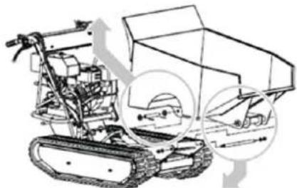
natural_image
Technical line drawing of a tracked robotic vehicle with mechanical components and motion arrows (no text or symbols)
natural_image
Technical line drawing of a mechanical assembly with no visible text or symbols


natural_image
Close-up of a green industrial vehicle with numbered components (1, 2, 3) and yellow circular annotations on the wheel (no readable text or symbols)
natural_image
Close-up of a mechanical component with circular annotation labeled '1' (no readable text or symbols)
natural_image
Close-up of metallic bolts and a mechanical component (no visible text or symbols)
- Position the bottom panel inside the mounting bracket.
- Align the holes with the mounting bracket.
- Insert a long pin through holes and secure each side with a flat washer and cotter pin.
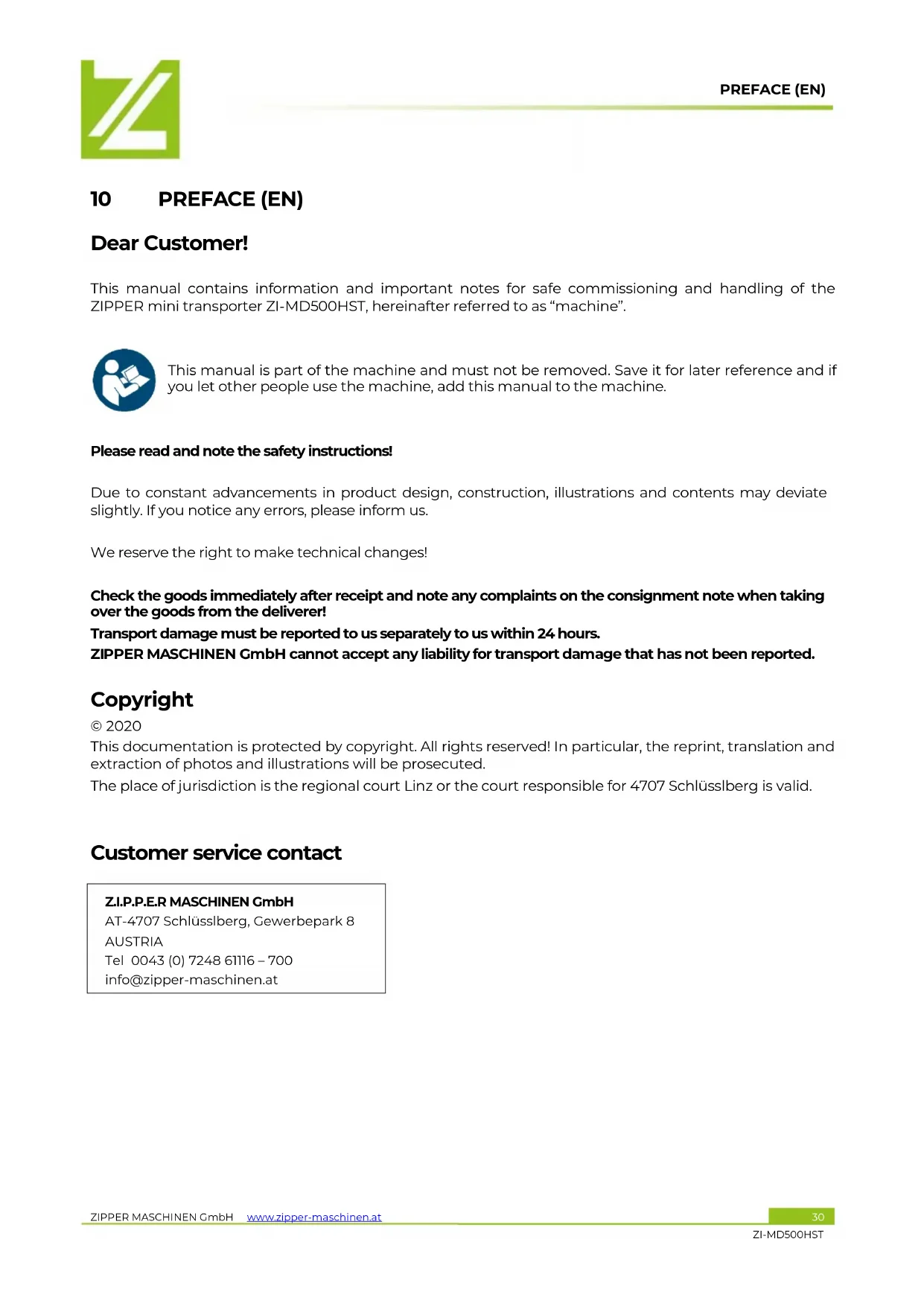
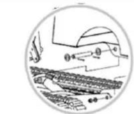
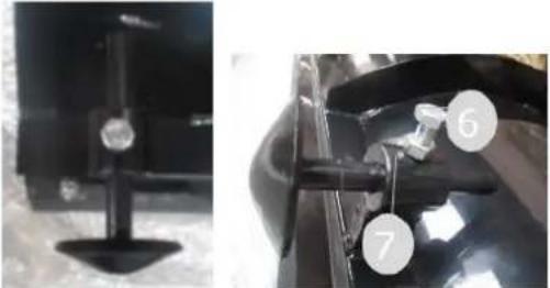
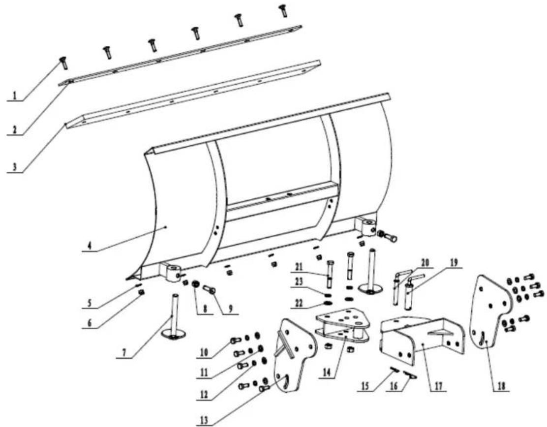
Snow blade:
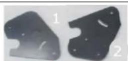
- Mount the mounting brackets (1) & (2) to the blades using M10×25 hex bolts, washers and nuts (3).
- Mount the bracket (4) to the mounting brackets (1) & (2) using in total four M10x25 hex bolts and washers.
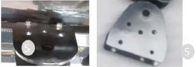
 |  | Mount the bracket (5) onto the snow blade using 2 hex-bolts. |
 | 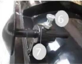 | Mount the Landing Leg weldment onto the snow blade. Place the landing leg weldment into the bracket and fix it with the hex bolt (6) and nut (7). |
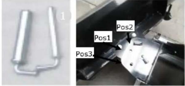
 |  | Install the already assembled snow blade on- to the machine with the two delivered pins.The snow blade can be tilted in three posi-tions:- Straight position place bolt (1) in position (Pos1).- Tilt it to the right place bolt (1) in position (Pos2).- Tilt it to the right place bolt (1) in position (Pos3). |
13 OPERATION
Device to be operated in a perfect state only. Inspect the device visually every time it is to be used. Check in particular the safety equipment, controls and screwed connection for damage and if tightened properly. Replace any damaged parts before operating the device.
13.1 Operating instructions
NOTE

• Disengage clutch lever before starting the engine
• Always guide the unit with both hands
• First engage, then accelerate
• Do not overload the machine capacity
• Always make certain that the weight is evenly balanced
• Change the gears only when the machine stands still!
- Go up slopes in one turn without stopping
- Do not tipping on soft ground
• Before start operating, check the dump box to make sure it is locked
• Attention: While tipping the centre of gravity will change
13.2 Function of components
1 Engine switch: The engine switch must be in the ON position for the engine to run.
Turning the engine switch to the OFF position stops the engine.
2 Throttle control: Controls engine speed. Put the throttle control on low speed (L) or high speed (H).
3 Right steering lever: Operate the lever to turn right.
4 Clutch control lever: Squeeze the lever, clutch engaged. Release the lever, clutch disengaged.
5 Left steering lever: Operate the lever to turn left.
7 Gear selection lever: Controls forward (3x) or reverse (1x) movements of the machine.
8 Tipping handle: Controls the tipping of the dump box.
13.3 Start up
T331 Fill in engine oil
WARNING

ATTENTION! For transport motor oil has been drained. Fill up with 4-stroke quality motor oil before first operation! Failure to do so will result in permanent motor damage and void guarantee!
NOTE

A too low oil level will cause damage to the engine and shorten the service life of the machine. Therefore, check the motor oil level before every start and if necessary fill up with oil.


natural_image
Technical line drawing of a mechanical clamp or bracket with a connector (no text or symbols)
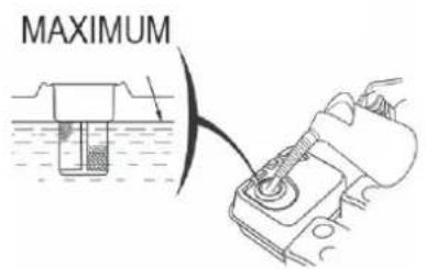
lower limit
- To check the engine oil level, place the machine on a flat, level surface. Switch off the motor and wait for ten minutes to allow the circulating oil to collect in the oil pan.
-
Unscrew the oil-dipstick and wipe with a clean, lint-free cloth or a non-fibrous paper towel.
-
Push the dipstick back into the opening as far as possible, but do not screw it in. (Make sure that the dipstick is really pushed in completely - occasionally it gets jammed).
-
Pull out the oil dipstick again and check the oil level. There are two markings for this - see illustration on the left.
- If the oil level is low, fill up the recommended oil to the upper rim at the maximum (maximum filling volume: see technical data: do not overfill!)
- Insert the oil dipstick again and retighten it.
- Wipe away oil residues.
T332 Refuel
WARNING
Use only unleaded fuel with min. 95 octane (corresponding device fuel) Never use 2-stroke mixture of diesel! DAMAGE OF ENGINE!
NOTE

Follow the safety instructions for fuel control. Filter the fuel before refuelling to prevent foreign particles from entering the combustion chamber. Wipe up spilled fuel.

- Refuelling only outdoors!
- Before removing the fuel tank cap, turn the motor off and let the machine cool down.
- Clean the fuel tank cap area.
- Remove the fuel tank cap carefully.
- Visual check of the filling level.
- If necessary, refill with fuel.
- Fuel tank capacity: see technical data. Fill tank only up to 1.5 cm below the rim of the filler neck, so that the fuel has place for expansion.
NOTE: use fuel with the appropriate octane number (RON 95).
-
Replace and tighten the fuel tank cap.
-
Wipe any fuel residues and wait until it evaporates.
1333 Check hydraulic oil
In the hydraulic oil tank must be approximately 3,5 liters of hydraulic oil (HL 46 or similar).
13.4 Operation
B4.1 Start Engine
Start the engine, if you have your wheeled dumper mounted correctly:
- Set the gear selection lever (7) to the neutral position.
- Move the choke lever on the machine to the full choke position.
• Turn engine switch to "ON".
• Pull the starter rope several times so that the carburettor is filled with gasoline. - Pull the starter handle, pull-out until resistance is felt. Let the rope rewind slowly across and then move expeditiously.
- Run the pull-starter handle slowly to the rope guide back as soon as the engine starts.
- Set the choke lever after a few seconds of engine run position "OPEN"
To start the engine is warm the choke lever is not to be operated.
- When the engine is warmed up, place the gear lever (7) (forward / reverse) in the desired position. If the desired gear cannot load, press the clutch lever short and repeat the process. After inserting the gear lever Push the clutch lever and the mini transporter begins to drive. Drag to adjust the throttle lever to the speed accordingly.
- With the steering arm on the handles and can be easily controlled. To drive in the desired direction each use the right or left steering lever.
B42 Idle speed
Throttle lever to the "SLOW" (SLOWLY) take to protect the motor if no work is done.
Downshifting the engine to idle prolongs the life of engine reduces fuel consumption and the noise level of the machine.
1343 Stop the engine
To stop the engine, release the clutch lever and turn the switch on the motor to the "OFF" position. Under normal conditions, proceed as follows.
a. Move the throttle lever to the SLOW position.
b. Allow engine to idle for 1-2 minutes.
c. Turn engine switch to OFF "OFF".
d. Turn the fuel valve lever to OFF.
ATTENTION: Not move the choke lever to stop the engine to CHOKE. Risk of reignition or damage to the engine!

NOTES
- The steering characteristics change proportional to the speed driven and the laden weight. The lightly loaded machine can be steered with lighter lever operation. With higher loading of the steering lever to control with higher pressure.
- The highest loadings of the machine is according to the floor on which the machine is used to adjust.
- It is therefore recommended to drive on difficult tracks in a low gear and with caution. In such situations, the machine to be driven over the entire range in a low gear.
- Avoid sharp turns and frequent changes of direction when driving on the road, especially on rough, tough terrain, which has many sharp, uneven areas, causing high friction.
- Although the machine has rubber tracks, please remember, to be careful when working under adverse weather conditions (ice, rain and snow) or on soils where the machine could be unstable.
- When the clutch lever is released, the machine is automatically braked and stops.
• If the machine is stopped on steep slopes, one of the tracks must be secured with a wedge.
1344 Dump box lifting and lowering ZI-MD500HST

- Pull the locking plate to the direction A and unlock the tipping handle.
- To raise the dump box, pull the tipping handle up to the direction B. The hydraulic system operates raising the dump box.
- To lower the dump box, pull the tipping handle down to the direction C. The hydraulic system operations lowering the dump box.
- When the dump box is lowered in original position lock the tipping handle with the locking plate.
14 MAINTENANCE
CAUTION


No cleaning, upkeep, checks or maintenance when machine is running.
Shut off the machine and let it cool down before start servicing!
The machine does not require intense maintenance. However, to ensure a long lifespan, we strongly recommend following the upkeep and maintenance plan.
Repairs must be carried out by specialists! Use original ZIPPER parts only!
NOTE

Only a properly maintained equipment may be a satisfactory tool. Care and maintenance deficiencies can cause unpredictable accidents and injuries.
Repairs should be performed only by authorized service centers.
Improper operation may damage the equipment or endanger your safety.
14.1 Maintenance plan
| Controls for the maintenance of the machine | |
| Regularly prior to each operation | Loose or lost screws, nuts, bolts |
| Regularly prior to each operation | Damage of any part of the machine |
| Regularly prior to each operation Fuel tank of tightness | |
| Regularly prior to each operation Track checking | |
| Regularly after operation Machine cleaning | |
| Every 25 working hours Lubricate the moving parts | |
| Every 25 working hours | Cleaning spark plug |
| Every 20-30 working hours | Cleaning air filter |
| Every 50 working hours Oil level checking | |
14.2 Cleaning
Clean the machine and the working attachment from soil, dust, grass, chips, and small twigs, etc.
NOTE

The use of solvents, harsh chemicals or abrasive cleaners leads to damage to the machine!
Therefore: When cleaning, use only mild detergents. The use of high pressure cleaners is not recommended. It shortens the service life and reduces the operational integrity. (Water car get into the gear!)
Impregnate bare surfaces of the machine against corrosion (e.g., anti-rust WD40).
14.3 Engine
Information about engine maintenance you can find in operation manual of the engine manufacturer!
14.3.1 Engine oil exchange
The engine oil change would be explicitly mentioned here in order to be included in the machine operating manual. Oil change interval after the first 20h or 1 month after commissioning and then every 100h or 1x per year.
NOTE


Waste oils are toxic and must not be released into the environment!
Contact your local authorities for information on proper disposal.

- Remove the oil drain plug (1) from the engine.
- Open the oil tank cap (2). Collect the draining oil in a collection container and dispose of it properly.
- Retighten the oil drain plug after draining.
- Fill in fresh oil through the filling opening (3) (see section Checking the engine oil level).
Use only high quality engine oil, e.g: SAE30, 15W40 or similar!
NOTE

Drain the used oil when the engine is warm. Warm oil drains quickly and completely.
1432 Check hydraulic oil
NOTE

Waste oils are toxic and must not be released into the environment!
Contact your local authorities for information on proper disposal.

natural_image
Mechanical assembly diagram showing internal components with numbered annotations (1 and 2), no readable text or symbols present.
natural_image
Close-up of a hand adjusting a mechanical component with a numbered label (3) on the part, no visible text or symbols beyond the number.- Loosen the hydraulic pipe (2) to drain the old hydraulic oil into a suitable container.
- After the hydraulic oil tank has been completely emptied, retighten the hydraulic pipe (2).
- Remove the oil dipstick (1) and add the oil. The recommended hydraulic oil is 10W AW32, ASLE H-150 or HLP 32.
Oil capacity of the hydraulic system: see technical data.
- Check the correct oil level by means of the marking (3) on the dipstick after filling.
14.4 Gearbox
1441 Check gearbox oil
The gearbox is pre-lubricated and sealed at the factory. Unless there is evidence of leakage or service has been performed on the gearbox, no additional lubricate should be required until 50 hours of use. For future use, check the oil level after every 50 hours of use.
NOTE

Waste oils are toxic and must not be released into the environment!
Contact your local authorities for information on proper disposal.
If you remove the oil level plug and no oil flows out, please add oil and then screw the oil level plug.
NOTE: recommended motor oil: GL-5, GL-6, SAE80W-90. Do not use synthetic oil!
If you want to replace oil, place the machine on a level ground. The machine must be stopped and still warm. Unscrew the filter cap and the drain plug. When the oil is drained, replace the drain plug, fill up with fresh oil and then replace the filter cap.
14.5 Clutch
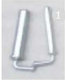
As clutch wears out, the same lever could have a wider opening, being so uneasy to use. To enable proper operation, the clutch cable must be adjusted:

- Loosen the jam nut (1) by turning it counter clockwise with 10 mm wrench.
- The clutch lever is set to the original position with the adjusting nut (2).
- Then retighten the lock nut (1).
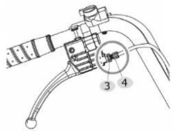
14.6 Steering
If you have difficulty steering the unit, you will need to adjust the steering levers with the special adjusters.
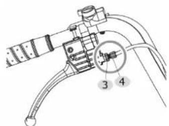
- Loosen the jam nut (3) by turning it counter clockwise with 10 mm wrench.
- Unscrew the adjust nut (4) to eliminate the play in the cable, which can occur after initial use or normal wear. Be very careful not to unscrew the adjust nut too much because this can create another problem: the loss of traction.
- Then retighten the lock nut (3).
If the above adjustment does not create enough cable tension, follow the steps below:

- Loosen the jam nut (5) by turning it counter clockwise with 10 mm wrench.
- Unscrew the adjustment nut (6) to eliminate the play in the cable. (do not to unscrew the adjust nut too much because this can create another problem: the loss of traction).
- Retighten the lock nut (5).
14.7 Tracks
14.7.1 Tightening
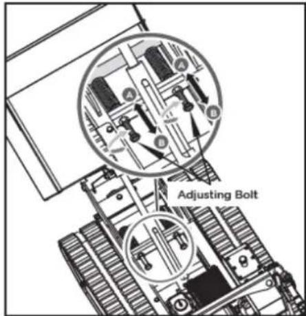
With use, tracks tend to loosen. When operating with loose tracks, they tend to slip over the driving wheel causing it to jump its housing or to work in precarious situation, thus damaging wear to the housing.
To check track tightness, proceed as follows:
a. Set the machine on a flat surface with compact ground, better on an asphalt or stone pavement.
b. Lift the machine and set it on blocks or supports rated for the weight of the machine so that the tracks are approximately 100mm off the ground.
c. Measure the track midline vs. the horizontal line. The reading must not be more than 10 - 15mm.
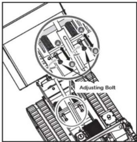
If the distance is greater, proceed as follows:
a. Use the tipping handle to tip the dump box and set it on blocks or supports rated for the weight of the box.
b. Loosen the locknut A. Tighten bolt B until the correct tightness is restored.
c. Secure bolt B by tightening locknut A thoroughly.
d. Return the dump box to its original position
WARNING
The adjustment of the chains affect the brakes. Please with great caution proceed as a chain spanned loss of braking action results.
If the adjustment does not allow further adjustment more, the chain should be replaced.
e. Tilting bring back to the starting position.
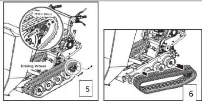
14.72 Replacing tracks
Check the condition of the tracks periodically. If any track is cracked or frayed, it should be replaced as soon as convenient.
WARNING
When removing and replacing the chain, make sure that you pinching your hands between the wheel and the chain.


natural_image
Technical line drawing of a tracked robotic vehicle with visible mechanical components and no text or symbols- Lift up the hopper and insert a support rod for safety purpose or disassemble the hopper.
- Lift the machine and set it on blocks or supports rated for the weight of the machine so that the tracks are approximately 10 cm.
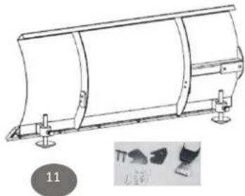
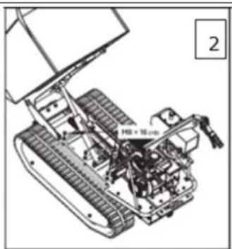
- Remove the three M8x16 bolts and washers that fix the track protection guard. (Picture 2)

- Remove the two M10 nuts and washers from the side track protection guard. (Picture 3)
-
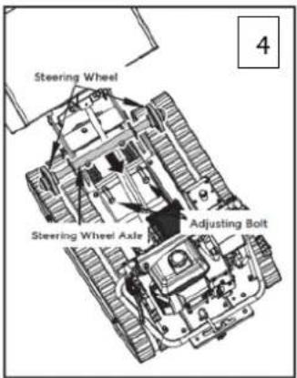
Loosen the adjustable bolts and pull the steering wheel axle toward the engine, then track will be loosen. (Picture 4)
-
Remove the M10x60 bolt, washers and nut from the driving wheel. (Picture 5)
-
Pull out the whole track with driving wheel and assemble the new track. (Picture 6)
-
In reverse order, repeat the upper steps to fix the chain and the track protection wheel guard to finish the track-replacing work.
14.8 Air filter
NOTE: Dirty air filters reduce the engine power due to insufficient air flow to the carburetor. Regular monitoring, especially in dusty atmosphere is therefore essential!
ATTENTION: Never clean the air filter elements with gasoline or flammable solvents: Warning. Fire or explosion!
Do not run the engine without an air filter: This dust penetrates through the carburetor and causing premature wear
14.9 Storage
If the machine is stored for longer than 30 days:
- Let the machine cool down.
- Clean the machine and dry.
• Empty Tank and carburetor completely, avoid fuel spillage.
• Store in a dry, out of reach of children place, well packaged.
14.10 Disposal
Observe the national waste disposal regulations. Never dispose of the machine, machine components or operating equipment in the residual waste. If necessary, contact your local authorities for information regarding available disposal options.
If you purchase a new machine or equivalent equipment from your specialist dealer, he is obliged in certain countries to dispose of your old machine properly.
15 TROUBLESHOOTING
| Trouble Possible cause | Trouble | |
| Engine will not start | Incorrect starting sequence | Observe the correct starting sequence |
| Dirty air filter | Clean/replace air filter | |
| No fuel supply | Refuel | |
| Fault in the fuel line | Check the fuel line for kinks or damages | |
| Engine flooded | Screw off, clean and dry the spark plug. Then pull the cranking rope several times and reinstall the spark plug | |
| Spark plug connector not placed on. | Place on the spark plug connector | |
| No ignition spark | Clean/replace spark plugCheck ignition cable | |
| Engine starts and is stalled immediately | Incorrect idle adjustment | Contact customer service |
| Machine works with interruptions | Carburetor incorrectly adjusted | Contact customer service |
| Spark plug fouled | Clean/replace spark plugCheck spark plug connector | |
| Machine does not work with full performance | Machine overloaded | Too much pressuresoil too tough |
| Dirty air filter | Clean/replace air filter | |
| Carburetor incorrectly adjusted | Contact customer service | |
| Machine does not run while the engine is running | Gear is not engaged properly | Switch shift lever in right position |
NOTE

Should you in necessary repairs not able to properly to perform or you have not the prescribed training for it always attract a workshop to fix the problem.
16 PRÓLOGO (ES)
¡Estimado cliente!:
natural_image
Technical line drawing of a mechanical clamp or bracket assembly (no text or symbols)

natural_image
Technical line drawing of a tracked robotic vehicle with visible mechanical components and no text or symbolsCher client, chère cliente,

natural_image
Technical line drawing of a mechanical clamp or bracket assembly with a connector (no text or symbols)
natural_image
Close-up of a mechanical vehicle chassis with visible components and wiring (no text or symbols)
natural_image
Close-up of a mechanical device with a hand adjusting a component, no visible text or symbols
natural_image
Technical line drawing of a tracked robotic vehicle with visible tracks and components (no text or symbols)


natural_image
Mechanical assembly diagram showing a tracked vehicle with gears and chains (no text or symbols)natural_image
Close-up of a green industrial vehicle chassis with numbered components (no visible text or symbols)Snježni plug:
- Montirajte nosače (1) i (2) sa 6 vijaka M10x25, odstojnicima i maticama (3).
 | • Pričvrstite držač (4) na nosače (1) i (2) s 4 vijka M10x25 i odstojnicima. |
 | • Pričvrstite držač (5) na snježni plug s 2 vijka. |
 | • Montirajte produžne noge na snježni plug: Da biste to učinili, postavite produžnu nogu u držač na snježnom plugu i pričvrstite je vijkom (6) i maticom (7). |
 | • Montaža cijelog snježnog pluga na stroj s dva vijka.• Snježni plug može imati 3 kutna položaja:- (ravno (vijak (1) u položaju rupe (poz. 1)- zakrenut udesno - položaj rupe (poz. 2) i- zakrenut u lijevo pozicija rupe (Poz. 3) |
31 RAD
natural_image
Technical line drawing of a mechanical clamp or bracket assembly (no text or symbols)
Donja granica
natural_image
Mechanical assembly with labeled parts, no visible text or symbols
natural_image
Close-up of a mechanical assembly with a hand adjusting a component, no visible text or symbols- Otpustite hidraulički vod (2) kako biste ispustili staro hidraulično ulje u odgovarajući spremnik.
- Nakon što je spremnik hidrauličkog ulja potpuno ispražnjen, ponovno zategnite hidraulički vod (2).
-
Izvucite mjernu šipku (1) i napunite hidraulično ulje. Spremnik hidrauličkog ulja ima kapacitet: vidi tehničke podatke. Preporučeno hidraulično ulje: HLP46; 10W AW32, ASLE H-150 ili HLP 32.
-
Provjerite ispravnu razinu ulja pomoću oznake (3) na mjernoj šipki nakon punjenja.
324 Prijenosnik
- Otpustite sigurnosnu maticu (1) okretanjem u smjeru suprotnom od kazaljke na satu pomoću ključa od 10 mm.
- Poluga kvačila se pomoću uređaja za podešavanje (2) vraća u prvobitni položaj.
- Zatim pritegnite ponovno kontra maticom (1).
32.6 Upravljanje
- Otpustite sigurnosnu maticu (3) okretanjem u smjeru suprotnom od kazaljke na satu pomoću ključa od 10 mm.
- Otpustite maticu za podešavanje (4) kako biste uklonili opuštenost kabela koja se može pojaviti nakon prve uporabe ili kod normalnog trošenja. Pazite da ne odvrnete vijke za podešavanje previše jer to može dovesti do drugog problema: gubitka vuče.
- Ponovno zategnite sigurnosnu maticu (3).
- Otpustite sigurnosnu maticu (5) okretanjem u smjeru suprotnom od kazaljke na satu pomoću ključa od 10 mm.
- Odvijte napravu za podešavanje (6) (ne previše, inače će doći do gubitka vuče!) i uklonite zračnost u sajli.
- Ponovno zategnite sigurnosnu maticu (5).
32.7 Pogonski lanac
327.1 Zatezanje

natural_image
Technical line drawing of a tracked robot with visible mechanical components and no text or symbols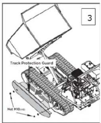

- Rastavite spremnik za istovar ili ga podignite do kraja i poduprite šipkom.
- Postavite stroj na ravnu površinu s čvrstom podlogom.
- Podignite stroj i postavite ga na postolje ili oslonce koji mogu podnijeti težinu stroja.
- Odvijte 3 M8x16 vijka s pokrovne ploče rotora (slika 2)
- Uklonite 2 M10 matice i podloške sa strane pokrovne ploče rotora. (Slika 3)
- Otpustite sigurnosnu maticu A i vijak B i povucite osovinu kotača prema motoru.

- Uklonite M10x60 vijak, podlošku i maticu s pogonskog kotača. (Slika 5)
- Skinite stari lanac i montirajte novi lanac.
- Ponovite gornje korake obrnutim redoslijedom za pričvršćivanje poklopca lanca i rotora kako biste dovršili promjenu lanca.
32.8 Zračni filter
Napomena: Prljavi filtri zraka smanjuju rad motora zbog nedovoljnog dovoda zraka u rasplinjač. Stoga su redovite provjere, osobito u prašnjavoj atmosferi, neophodne!
Nemojte pokretati motor bez zračnog filtra: Prašina ulazi kroz rasplinjač i uzrokuje prijevremeno trošenje
Pozor: Nikada nemojte čistiti elemente filtara za zrak benzinom ili zapaljivim otapalima. Opasnost od požara ili eksplozije!
32.9 Skladištenje
Ako je stroj uskladišten dulje od 30 dana:

natural_image
Two black metal bracket components labeled 1 and 2, with a close-up of a green mechanical component being cut (no text or symbols visible)
natural_image
Close-up of a green industrial vehicle chassis with numbered components (no visible text or symbols)- Postavite spremnik za istovar u nosač.
- Poravnajte rupe s nosačem.
- Provucite osovinu kroz rupe i pričvrstite svaku stranu odstojnikom i klinom.
Snežni plug:
- Montirajte nosače (1) i (2) sa 6 zavrtnja M10x25, odstojnicima i maticama (3).
 | • Pričvrstite držač (4) na nosače (1) i (2) s 4 zavrtnja M10x25 i odstojnicima. |
 | • Pričvrstite držač (5) na snežni plug s 2 zavrtnja. |
 | • Montirajte produžne noge na snežni plug: Da biste to učinili, postavite produžnu nogu u držač na snežnom plugu i pričvrstite je zavrtnjem (6) i maticom (7). |
| • Montaža celog snežnog pluga na mašinu s dva zavrtnja.• Snežni plug može imati 3 ugaona položaja:- (ravno (zavrtanj (1) u položaju rupe (poz. 1)- zaokrenut udesno - položaj rupe (poz. 2) i- zaokrenut u levo pozicija rupe (Poz. 3) |
37 RAD
Koristite mašinu samo kada je u savršenom stanju. Izvršite vizuelni pregled mašine pre svakog korišćenja. Sigurnosni uređaji i radni elementi moraju vrlo pažljivo da se provere. Proverite jesu li vijčani spojevi oštećeni i zategnuti.
37.1 Uputstva za upotrebu
NAPOMENA

- Za proveru nivoa motornog ulja, postavite mašinu na sigurnoj, ravnoj površini. Ugasite motor i ostavite mašinu deset minuta kako bi se ulje koje cirkuliše skupilo u koritu ulja.
- Odvijte mernu šipku za ulje i obrišite je čistom krpom koja ne ostavlja dlačice ili papirnim ubrusom koji ne ostavlja dlačice.
- Gurnite mernu šipku nazad u otvor koliko god može, ali je nemojte zavrnuti. (Uverite se da je šipka gurnuta do kraja - ponekad se zaglavi.)

natural_image
Technical line drawing of a mechanical clamp or bracket assembly (no text or symbols)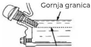
Donja granica
- Ponovno izvucite šipku za merenje ulja i očitajte nivo ulja. Za to postoje dve oznake – vidi sliku levo.
- Ako je nivo ulja nizak, dolijte preporučeno ulje do gornje ivice.
- Gurnite mernu šipku za ulje nazad i zategnite je.
- Očistite mašinu od prolivenog ulja.
3732 Punjenje gorivom
UPOZORENJE
Točite samo bezolovni benzin RON 95 (ili ekvivalentni benzin za opremu)! Nikada ne dolevajte gorivo dvotaktnom smesom ili dizelom. ŠTETA NA MOTORU!
NAPOMENA

Pridržavajte se sigurnosnih uputstava za proveru goriva. Filtrirajte gorivo tokom punjenja kako biste sprečili ulazak stranih čestica u komoru za sagorevanje. Obrišite gorivo koje se prolilo.
- Točite gorivo samo na otvorenom!
- Pre skidanja poklopca rezervoara, isključite motor i ostavite mašinu da se ohladi.
- Očistite područje poklopca rezervoara.
- Pažljivo uklonite poklopac rezervoara.
- Provera nivoa u obliku vizualne provere.
- Dodajte gorivo ako je potrebno.
- Zapremina rezervoara motora, vidi tehničke podatke. Napunite rezervoar ne više od 1,5 cm ispod ivice gr la za punjenje da biste dali prostor za Gorivo da se proširi.
NAPOMENA: Ako je potrebno, dolijte benzin s odgovarajućim oktanskim brojem (ROZ 95). - Ponovno zavrnite čep rezervoara.
- Obrišite sve ostatke goriva i pričekajte da pare nestanu.
37.3.3 Proverite hidraulično ulje
- Povucite ručicu za zaključavanje A prema gore za otključavanje.
- Za podizanje kontejnera za istovar, povucite polugu za preokretanje prema gore u smeru B. Hidraulični sistem podiže kontejner za istovar.
- Za spuštanje kontejnera za istovar, gurnite polugu za prevrtanje prema dole u smeru C. Kontejner za istovar se ponovno spušta.
- Nakon završetka procesa istovara i pre nastavka vožnje, ponovno zaključajte polugu za istovar pomoću ručke za zaključavanje.
38 ODRŽAVANJE
PAŽNJA


Pre radova na održavanju isključite mašinu i pustite je da se ohladi!
Mašina zahteva malo održavanja i sadrži samo nekoliko delova koje operater treba da servisira. Greške ili kvarove koji bi mogli ugroziti sigurnost mašine odmah otklonite.
NAPOMENA

- Uklonite zavrtanj za ispuštanje ulja (1) na motoru.
- Otvorite čep rezervoara za ulje (2). Ispušteno ulje sakupite u rezervoar i propisno ga odložite!
- Ponovo zategnite čep za ispuštanje ulja nakon ispuštanja.
- Dolijte sveže ulje kroz otvor za punjenje (3) (pogledajte odeljak Provera nivoa motornog ulja).
Koristite samo motorno ulje visokog kvaliteta, npr.: SAE30, 15W40 ili slično!
NAPOMENA

natural_image
Mechanical assembly with labeled parts, no visible text or symbols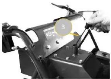
natural_image
Close-up of a mechanical assembly with a hand adjusting a component, no visible text or symbols- Otpustite hidraulični vod (2) kako biste ispustili staro hidraulično ulje u odgovarajući rezervoar.
- Nakon što je rezervoar hidrauličnog ulja potpuno ispražnjen, ponovno zategnite hidraulični vod (2).
-
Izvucite mernu šipku (1) i napunite hidraulično ulje. Rezervoar hidrauličnog ulja ima kapacitet: vidi tehničke podatke. Preporučeno hidraulično ulje: HLP46; 10W AW32, ASLE H-150 ili HLP 32.
-
Proverite ispravan nivo ulja pomoću oznake (3) na mernoj šipki nakon punjenja.
38.4 Menjač
38.41 Provera ulja menjača
- Otpustite sigurnosnu maticu (1) okretanjem u smeru suprotnom od kazaljke na satu pomoću ključa od 10 mm.
- Poluga kvačila se pomoću uređaja za podešavanje (2) vraća u prvobitni položaj.
- Zatim pritegnite ponovno kontra maticom (1).
38.6 Upravljanje

- Otpustite sigurnosnu maticu (3) okretanjem u smeru suprotnom od kazaljke na satu pomoću ključa od 10 mm.
- Otpustite maticu za podešavanje (4) kako biste uklonili opuštenost kabla koja se može pojaviti nakon prve upotrebe ili kod normalnog trošenja. Pazite da ne odvrnete zavrtnje za podešavanje previše jer to može dovesti do drugog problema: gubitka vuče.
- Ponovo zategnite sigurnosnu maticu (3).
- Otpustite sigurnosnu maticu (5) okretanjem u smeru suprotnom od kazaljke na satu pomoću ključa od 10 mm.
- Odvijte uređaj za podešavanje (6) (ne previše, inače će doći do gubitka vuče!) i uklonite zazor u sajli.
- Ponovo zategnite sigurnosnu maticu (5).
38.7 Pogonski lanac
38.7.1 Zatezanje

natural_image
Technical line drawing of a tracked robotic vehicle with visible tracks and components (no text or symbols)
- Rastavite kon tejner za istovar ili ga podignite do kraja i poduprite šipkom.
- Postavite mašinu na ravnu površinu s čvrstom podlogom.
- Podignite mašinu i postavite je na postolje ili oslonce koji mogu podneti težinu mašine.
- Odvijte 3 M8x16 zavrtnje s pokrovne ploče rotora (slika 2)
- Uklonite 2 M10 matice i podloške sa strane pokrovne ploče rotora. (Slika 3)
- Otpustite sigurnosnu maticu A i zavrtanj B i povucite osovinu točka prema motoru.
- Uklonite M10x60 zavrtanj, podlošku i maticu s pogonskog točka. (Slika 5)
- Skinite stari lanac i montirajte novi lanac.
- Ponovite gornje korake obrnutim redosledom za pričvršćivanje poklopca lanca i rotora kako biste dovršili promenu lanca.
38.8 Filter vazduha
Napomena: Prljavi filteri vazduha smanjuju rad motora zbog nedovoljnog dovoda vazduha u karburator. Stoga su redovne provere, naročito u prašnjavoj atmosferi, neophodne!
Nemojte pokretati motor bez filtera vazduha: Prašina ulazi kroz karburator i uzrokuje prevremeno trošenje Pažnja: Nikada nemojte da čistite elemente filtera za vazduh benzinom ili zapaljivim rastvaračima. Opasnost od požara ili eksplozije!
38.9 Skladištenje
Ako se mašina skladišti duže od 30 dana:
- Pričekajte dok se mašina dovoljno ne ohladi.
- Ispustite gorivo iz rezervoara i karburatora u odgovarajuću posudu i sačuvajte ispušteno gorivo u odgovarajuću posudu.
• Mašinu dobro pokrijte i skladištite na suvo i čisto mesto.
38.10 Odlaganje

natural_image
Technical line drawing of a mechanical clamp or bracket assembly with a connector (no text or symbols)
natural_image
Close-up of a mechanical vehicle showing internal components and wiring (no visible text or symbols)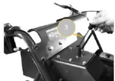
natural_image
Close-up of a mechanical component with a hand adjusting parts, no visible text or symbols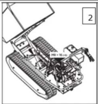
natural_image
Technical line drawing of a tracked robotic vehicle with visible mechanical components and no text or symbols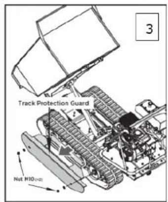

(EN) With original ZIPPER spare parts you use parts that are attuned to each other shorten the installation time and elongate your products lifespan.
NOTE

The installation of parts other than original spare parts leads to the loss of the guarantee! Therefore: When replacing components/parts, only use spare parts recommended by the manufacturer.
Order the spare parts directly on our homepage – category SPARE PARTS or contact our customer service
• via our Homepage – category SERVICE/NEWS - SPARE PARTS REQUEST,
• by e-mail to eg01@zipper-maschinen.at.
Always state the machine type, spare part number and designation. To prevent misunderstandings, we recommend that you add a copy of the spare parts drawing with the spare parts order, on which the required spare parts are clearly marked, especially when not using the online-spare-part catalogue.
Partlist ZI-MD500HST
| No | Part | Description | Qty | No | Part | Description | Qty | No | Part | Description | Qty |
| 1 | 09735R.10.101 | Bend Plate | 1 | 76 | GB/T 9877-1992 | Gasket 25x47x7 | 8 | 151 | 09710.37.122 | Gear III-2 | 1 |
| 2 | 95 6-100HV-BX | Washer a6 | 37 | 77 | GB/T 276-1994 | Bearing 6204-2RS | 16 | 152 | 09710.37.125 | Gear Shaft III | 1 |
| 3 | 93 6 BX | Spring washer 6 | 14 | 78 | Engine(9HP) | 1 | 153 | 09735R.37.113 | Gear Box Case (L) | 1 | |
| 4 | 889.1 M6 BX | Nut M6 | 13 | 79 | 09710.65.010 | Supporting Wheel woldment | 8 | 154 | JBZQ 4450-1997 | Plug M14x1.5 | 2 |
| 5 | 32631.04.101 | Handle sleeve | 2 | 80 | GB/T 96-2002 | Washer e10 | 14 | 155 | JB/T 982-1997 | Washer Groupware 14 | 2 |
| 6 | 09710.00.126 | Throttle Lever | 1 | 81 | GB/T 5783-2000 | Bolt M10X25 | 10 | 156 | 09710.37.139-2 | Gear Box Case Paper Spacer | 1 |
| 7 | 01120.24.017 | Throttle Cable | 1 | 82 | 09710.00.118 | p47 Axle Head Cover (Support Wheel) | 4 | 157 | 09720.37.101 | Output Shaft | 2 |
| 8 | SB.21.011a | Hoop | 1 | 83 | 09720.00.101 | Track 180x80x38 | 2 | 158 | 09710.37.128 | Gear II-1 | 1 |
| 9 | 70.1 M6x60 8.8 YH | Screw M6X60 | 1 | 84 | 09735.00.106 | Two-head Stud | 4 | 159 | 09710.37.127 | Bush 2 | 1 |
| 10 | 32545.00.016 | ON/OFF Switch | 1 | 85 | 09735.00.105 | Guard Plate (L) | 1 | 160 | 09710.37.124 | Bush 1 | 1 |
| 11 | SB.26.001B | Right/Left Steering Lever | 2 | 86 | GB/T 70.1-2000 | Screw M8x20 | 4 | 161 | GB/T 1096-200 | Key C5x20 | 2 |
| 12 | 70.1 M6x35 8.8 YH | Screw M6X35 | 1 | 87 | GB/T 6170-2000 | Nut M16 | 2 | 162 | 09710.37.116 | Spline Shaft II | 1 |
| 13 | 09710.00.103A | Right/Left Steering Lever Cable | 2 | 88 | 09720.30.158 | Guide Bolt | 2 | 163 | 4450 M18x1.5 | Plug M18x1.5 | 2 |
| 14 | 09735.10.010A | Right Handle Frame Assembly | 1 | 89 | 09735F.30.010 | Chassis Weldment | 1 | 164 | 09710.37.016 | Clutch Fork Shaft (R) | 1 |
| 15 | 70.2 M6x45 8.8 YH | Screw M6x45 | 5 | 90 | 09720A.00.107 | Optical Axis | 1 | 165 | 09735R.37.114 | Gear Box Case (R) | 1 |
| 16 | 70.3 M6x16 8.8 YH | Screw M6x16 | 1 | 91 | GB/T91 | Cotter Pin & 4X35 | 5 | 166 | GB/T 879.2-2000 | Pin 12x20 | 2 |
| 17 | 09735.10.021A | Left Handle Frame Assembly | 1 | 92 | 09735.30.117 | Rear Cover | 1 | 167 | GB/T 9877.1-86 | Seal FB16x22x4 | 2 |
| 18 | SB.25.001 | Clutch Control Lever | 1 | 93 | 09735.40.010A | Guide Wheel Axle | 1 | 168 | 09710.37.144-1 | Output Gear Bush Paper Spacer | 2 |
| 19 | 09735R.00.101A | Clutch Control Lever Cable | 1 | 94 | GB/T 9877.1-1992 | Gasket 42x30x7 | 2 | 169 | 09710.37.131 | Gasket 1 | 4 |
| 20 | 70.1 M5x20 8.8 YH | Screw M5x20 | 2 | 95 | GB/T 893.1-1986 | Circlip 42 | 4 | 170 | 09710.37.129A-1 | Clutch Spring | 2 |
| 21 | 889.1 M5 BX | Nut M5 | 2 | 96 | GB/T 276-1994 | Bearing 61905-2RS | 4 | 171 | 09710.37.134 | Spring Guide Bush | 2 |
| 22 | 09720.00.109-1 | Soleplate (L) | 1 | 97 | 09720.55.101 | Guide Wheel | 2 | 172 | 09710.37.136A-1 | Clutch Bush | 2 |
| 23 | 5783 M8x16 8.8 BX | Bolt M8x16 | 16 | 98 | 09710.00.123 | p47 Axle Head Cover (Guide Wheel) | 2 | 173 | 09710.37.135 | Spring Gasket | 2 |
| 24 | 95 8 100HV BX | Washer a8 | 43 | 99 | 09735.00.103 | Guard Plate (R) | 1 | 174 | GB/T 308 | Steel Ball 5 | 70 |
| 25 | 70.1 M10x20 8.8 BX | Screw M10x20 | 8 | 175 | GB/T 894.1-1986 | Circlip 58 | 2 | ||||
| 26 | 95 10 100HV BX | Washer a10 | 28 | 101 | 09710.50.010 | Large Belt Pulley Cover | 1 | 176 | 09710.37.138 | Output Gear | 1 |
| 27 | 93 10 BX | Washer a10 | 32 | 102 | GB/T12 | Bolt M6X20 | 1 | 177 | 09710.37.137 | Intermediate Joint Bush | 1 |
| 28 | 09735.10.020A | Handle Mounting Frame | 1 | 103 | 09735.20.001B | Dumper Box | 1 | 178 | 09710.37.143 | Intermediate Joint Bush Composite Bushing | 2 |
| 29 | 889.1 M8 BX | Nut M8 | 27 | 104 | 09735F.60.001 | Hydraulic System | 1 | 179 | GB/T 894.1-1986 | Circlip 26 | 2 |
| 30 | 5783 M8x25 8.8 BX | Bolt M8x25 | 6 | 105 | 09710.37.104 | Guard Cover | 1 | 180 | 09710.37.145-1 | Joint Bush | 2 |
| 31 | 5783 M8x20 8.8 BX | Bolt M8x20 | 9 | 106 | GB/T 879.2-2000 | Cylindrical Pin 5X30 | 1 | 181 | 09710.37.133 | Spring Gasket | 4 |
| 32 | 93 8 BX | Washer a8 | 8 | 107 | 09710.37.018 | Gearshift Lever II | 1 | 182 | GB/T 894.1-1986 | Circlip 25 | 2 |
| 33 | 09720.00.111-1 | Soleplate (R) | 1 | 108 | GB/T879.2 | Cylindrical Pin 3X30 | 1 | 183 | GB/T 9877.1-86 | Seal FB42x25x7 | 2 |
| 34 | 5781 M8x12 4.8 BX | Bolt M8x12 | 7 | 109 | 09710.37.105A | Locating Nut | 1 | 184 | GB/T 70.1-2000 | Screw M8x25 w/glue | 12 |
| 35 | 09735R.00.112 | Small Belt Pulley Cover 1 | 1 | 110 | JB/T982 | Washer Groupware 20 | 1 | 185 | GB/T 955 | Washer g8 | 10 |
| 36 | 09735R.00.110 | Upper Cover | 1 | 111 | GB/T 3452.1-2005 | D-ring 11.2X1.8 | 1 | 186 | 09720.37.014A-1 | Output Gear Bush Weldment | 2 |
| 37 | GB/T 1096-2003 | Key 7x40 | 1 | 112 | 09710.37.158A | Lever Mount Bracket | 1 | 187 | 09710.37.132 | Output Shaft Composite Bushing | 4 |
| 38 | 09735R.27.050B | Fixed Bracket | 1 | 113 | GB9877.1-86 | Seal FB17X40X7 | 2 | 188 | 01135.37.015 | Oil dipstick Assy | 1 |
| 39 | 09735E.27.042 | Tensioner Pulley Bracket | 1 | 114 | 09710.37.140 | Spine Shaft I | 1 | 189 | 09735.60.013 | Tank Cover | 1 |
| 40 | GB/T 96.2-2002 | Washer a8 | 9 | 115 | 09710.37.141-2 | Duplex Slip Gear | 1 | 190 | 09735.60.137Z | Asbestos Cushion | 1 |
| 41 | 09720.30.030 | Bolt Plate | 1 | 116 | 09710.37.142-2 | Gear | 1 | 191 | WU-16X100 | OIL FILTER | 1 |
| 42 | 09735F.30.103 | Spacer Bush | 1 | 117 | GB/T 276-94 | Bearing 6302 | 1 | 192 | 09735.60.010 | Tank | 1 |
| 43 | 09735.30.102 | Small Belt Pulley | 1 | 118 | 09710.37.106Z | Gearshift Fork Guide Pin | 1 | 193 | 09735.60.102 | Torsion Spring | 1 |
| 44 | GB/T 11544—1997 | Bolt B34 | 1 | 119 | 09710.37.107 | Small spring | 1 | 194 | 09735.60.103 | Returning Plate | 1 |
| 45 | 09735.27.122 | Rubber Gasket | 1 | 120 | GB/T 307-86 | Steel Ball 6 | 1 | 195 | GB/T5782-2000 | Bolt M6x30 | 4 |
| 46 | 09735.27.131 | Coupler Sleeve (12.7 ) | 1 | 121 | 09710.37.108 | Gearshift Fork | 1 | 196 | GB/T5783-2000 | Bolt M6x60 | 2 |
| 47 | 09735.27.107A | Pump Mounting Flange | 1 | 122 | 09710.37.026 | Rivet Assembly | 1 | 197 | 09735.60.101 | Tank Fixing Bracket | 1 |
| 48 | 09710.00.127-2 | Brake Cable | 1 | 123 | 09710.37.022 | Brake Disk Assy. | 1 | 198 | JB/T962 | Washer Groupware 18 | 6 |
| 49 | GB/T77 | Screw M8*10 | 4 | 124 | 09710.37.169 | Wearing Pad | 1 | 199 | 09735.60.145 | Connector | 4 |
| 50 | 09720.37.0017 | Gear Box Complete | 1 | 125 | 09710.37.225 | Sleeve | 3 | 200 | 09735.60.207 | Oil Outlet Pipe | 1 |
| 51 | M10X5色 | Lever | 1 | 126 | 09710.37.221 | Brake Pull Plate | 1 | 201 | 09735.60.146 | NPT3V8-M18X1.5 | 2 |
| 52 | GB/T 70.1-2000 | Screw M10X70 | 1 | 127 | GB/T894.1-1986|12 | Circlip 12 | 1 | 202 | 09735.60.144 | Pump | 1 |
| 53 | GB/T 889.1-2000 | Lock Nut M10 | 16 | 128 | 5287 6 100HV-BX | washer 6 | 5 | 203 | 09735.60.206A | Oil Inlet Pipe | 1 |
| 54 | 09710.37.146 | Driving Wheel | 2 | 129 | GB/T 5783-2000 | Bolt M6x16 | 4 | 204 | GB/T5782-2000 | Bolt M8x55 | 2 |
| 55 | GB/T 70.1-2000 | Screw M10X60 | 2 | 130 | 09710.37.025 | Expansion Brake Cover | 1 | 205 | 09735B.60.209 | Rubber hose | 2 |
| 56 | 09735R.00.113A | Small Belt Pulley Cover 2 | 1 | 131 | 09710.37.220 | Connecting Shaft | 1 | 206 | 09735B.60.040 | Welding Cylinder | 1 |
| 57 | GB/T 70.1-2000 | Screw M10X25 | 4 | 132 | 09710.37.111 | Vent-Plug Joint sleeve | 1 | 207 | 09735.60.106 | Spindle 2 | 1 |
| 58 | GB/T5783-2000 | Bolt M8x12 w/glue | 1 | 133 | 09710.37.110 | Vent-Plug | 1 | 208 | Oil Cup 6X1 | 2 | |
| 59 | GB/T 70.1-2000 | Screw M5x12 | 1 | 134 | GB/T 70.1-2000 | Screw M8x30 | 3 | 209 | 882_A20x95_BX | Pipe Clamp | 1 |
| 60 | GB/T 893.1-1986 | Circlip 35 | 1 | 135 | 09720.00.108 | Cushion | 2 | 210 | 09735.60.104 | Oil Return Pipe | 1 |
| 61 | GB/T 894.1-1986 | Circlip 15 | 1 | 136 | JB/T982 | Washer Groupware 6 | 1 | 211 | 09735.60.205 | Bolt M14x1.5 | 1 |
| 62 | GB/T 276-1994 | Bearing 6202-2RS | 2 | 137 | 01135.37.182 | Spongy Cushion | 1 | 212 | 09735.60.150 | Washer Groupware 14 | 1 |
| 63 | 09710.30.137 | Tensioner Pulley | 1 | 138 | GB/T 70.1-2000 | Screw M8x130 | 6 | 213 | 09735.60.143 | Reversing Valve | 1 |
| 64 | 09735.27.130 | Coupler Sleeve (25 ) | 1 | 139 | 09710.37.015 | Clutch Fork Shaft (L) | 1 | 214 | GB/T5783-2000 | Bolt M8x40 | 1 |
| 65 | 09710.00.119 | Wheel Shaft Press Plate | 2 | 140 | GB/T 5783 | Bolt M6x20 | 3 | 215 | 09735.60.108 | Pipe Clamp Plate | 1 |
| 66 | 09720.30.050 | Belt Plate | 1 | 141 | 09710.37.102-1 | Swing Plate | 2 | 216 | 09710.30.157 | Locating Sleeve | 2 |
| 67 | 09735R.27.101 | Locating Sleeve | 1 | 142 | 09710.37.120 | Gear III-4 | 1 | 217 | 09720.30.156 | Guiding Spring | 2 |
| 68 | 09710.00.117 | Support Plate (L) | 1 | 143 | 09710.37.121 | Gear III-3 | 1 | 218 | 09710.20.102 | Spring | 1 |
| 69 | 09710.00.011 | Gearshift Panel | 1 | 144 | 09710.37.159B | Large Belt Pulley | 1 | 219 | 5783 M10x35 8.8 | Bolt M10x35 | 1 |
| 70 | GB/T 12-1988 | Bolt M8X45 | 4 | 145 | GB/T 276-94 | Bearing 6303 | 5 | 220 | 09720.37.017A | Gearshift Lever | 1 |
| 71 | 09710.30.021Z | Rubber Mat | 4 | 146 | 09710.37.117 | Gear II-5 |
Getriebe / Gearbox Pos 50

Hydraulik-System / hydraulic system Pos 104

Schneeschild / Snowblade / Escudo quitanieves / Chasse-neige / Snježni plug / Snežni plug / Hótolólap
Schneeschild / Snowblade ZI-MD500HST
| Pos | Part | Description | Qty | Pos | Part | Description | Qty |
| 1 | GB/T 12-1998 | Bolt M8X35 | 6 | 13 | 31450.15.020 | 1 | |
| 2 | 31450.10.113 | Shave Plate | 1 | 14 | 31450.15.040 | 1 | |
| 3 | 31450.10.115 | Rubber Plate | 1 | 15 | Bridge Pin 2X11X35 | 1 | |
| 4 | 31450.10.010B | Blade Weldment | 1 | 16 | Bridge Pin 3.5X23X70 | 1 | |
| 5 | GB/T 95-2002 | Washer8 | 6 | 17 | 31450.15.030 | 1 | |
| 6 | GB/T 889.1-2000 | Nut M8 | 6 | 18 | 31450.15.021 | 1 | |
| 7 | 31450.10.040 | Landing Leg Weldment | 2 | 19 | 31450.15.050 | 1 | |
| 8 | GB/T6170-2000 | Nut M12 | 4 | 20 | 31450.15.060 | 1 | |
| 9 | GB/T 5783-2000 | Bolt M12X40 | 2 | 21 | GB/T 5782-2000 | Bolt M12X70 | 2 |
| 10 | GB/T5783 | Bolt M10X25 | 10 | 22 | GB/T 95-2002 | Washer12 | 2 |
| 11 | GB/T 95-2002 | Washer10 | 8 | 23 | GB/T 93-2000 | Washer12 | 2 |
| 12 | GB/T 93-2000 | Washer10 | 8 |
Company ZIPPER Maschinen GmbH grants for mechanical and electrical components a warranty period of 2 years for amateur use; and warranty period of 1 year for professional use, starting with the purchase of the final consumer. In case of defects during this period, which are not excluded by paragraph 3, ZIPPER will repair or replace the machine at its own discretion.
2.) Report:
In order to check the legitimacy of warranty claims, the final consumer must contact his dealer. The dealer has to report in written form the occurred defect to ZIPPER. If the warranty claim is legitimate, ZIPPER will pick up the defective machine from the dealer. Returned shippings by dealers which have not been coordinated with ZIPPER, will not be accepted and refused.
3.) Regulations:
a) Warranty claims will only be accepted, when a copy of the original invoice or cash voucher from the trading partner of ZIPPER is enclosed to the machine. The warranty claim expires if the accessories belonging to the machine are missing.
b) The warranty does not include free checking, maintenance, inspection or service works on the machine. Defects due to incorrect usage of the final consumer or his dealer will not be accepted as warranty claims either. Some examples: usage of wrong fuel, frost damages in water tanks, leaving fuel in the tank during the winter, etc.
c) Defects on wear parts are excluded, e.g. carbon brushes, collection bags, knives, cylinders, cutting blades, clutches, sealings, wheels, saw blades, splitting crosses, riving knives, riving knife extensions, hydraulic oils, oil/air/fuel filters, chains, spark plugs, sliding blocks, etc.
d) Also excluded are damages on the machine caused by incorrect or inappropriate usage, if it was used for a purpose which the machine is not supposed to, ignoring the user manual, force majeure, repairs or technical manipulations by not authorized workshops or by the customer himself, usage of non-original ZIPPER spare parts or accessories.
e) After inspection by our qualified personnel, resulted costs (like freight charges) and expenses for not legitimated warranty claims will be charged to the final customer or dealer.
f) In case of defective machines outside the warranty period, we will only repair after advance payment or dealer's invoice according to the cost estimate (incl. freight costs) of ZIPPER.
g) Warranty claims can only be granted for customers of an authorized ZIPPER dealer who directly purchased the machine from ZIPPER. These claims are not transferable in case of multiple sales of the machine.
4.) Claims for compensation and other liabilities:
The liability of company ZIPPER is limited to the value of goods in all cases. Claims for compensation because of poor performance, lacks, damages or loss of earnings due to defects during the warranty period will not be accepted. ZIPPER insists on its right to subsequent improvement of the machine.
SERVICE
After Guarantee and warranty expiration specialist repair shops can perform maintenance and repair jobs. But we are still at your service as well with spare parts and/or product service. Place your spare part/repair service cost inquiry by
- Mail to service@zipper-maschinen.at.
- Or use the online complaint order formula provided on our homepage – category service/news.
51 GARANTÍA (ES)
1.) Garantía:
(EN) We monitor the quality of our delivered products in the frame of a Quality Management policy.
Your opinion is essential for further product development and product choice. Please let us know about your:
- Impressions and suggestions for improvement.
- Experiences that may be useful for other users and for product design
- Experiences with malfunctions that occur in specific operation modes
We would like to ask you to note down your experiences and observations and send them to us via E-Mail or by post:
- ZI-MD500HST
- Lieferumfang / delivery content / Volumen de suministro / Contenu de la livraison / Opseg isporuke / Obim isporuke / Szállítási terjedelem
- Technische Daten / technical data / Datos técnicos / Données techniques / Tehnički podaci / Tehnički podaci / Můszaki adatok
- VORWORT (DE)
- Please read and note the safety instructions!
- Copyright
- Customer service contact
- Intended use of the machine
- The machine is used for:
- NOTE
- WARNING
- T1.1 Prohibited applications / Dangerous misuse
- Safety instructions
- Remaining risk factors
- ASSEMBLY
- Assembly
- ZI-MD500HST
- Snow blade:
- OPERATION
- Operating instructions
- Function of components
- Start up
- T331 Fill in engine oil
- T332 Refuel
- Check hydraulic oil
- Operation
- B4.1 Start Engine
- Start the engine, if you have your wheeled dumper mounted correctly:
- To start the engine is warm the choke lever is not to be operated.
- B42 Idle speed
- Stop the engine
- NOTES
- Dump box lifting and lowering ZI-MD500HST
- MAINTENANCE
- CAUTION
- Maintenance plan
- Cleaning
- Engine
- Engine oil exchange
- Check hydraulic oil
- Gearbox
- Check gearbox oil
- Waste oils are toxic and must not be released into the environment!
- Clutch
- Steering
- Tracks
- Tightening
- To check track tightness, proceed as follows:
- If the distance is greater, proceed as follows:
- Replacing tracks
- Air filter
- Storage
- Disposal
- PRÓLOGO (ES)
- ¡Estimado cliente!:
- Cher client, chère cliente,
- Snježni plug:
- RAD
- Prijenosnik
- Upravljanje
- Pogonski lanac
- Zatezanje
- Zračni filter
- Skladištenje
- Snežni plug:
- RAD
- Uputstva za upotrebu
- NAPOMENA
- Punjenje gorivom
- UPOZORENJE
- Proverite hidraulično ulje
- ODRŽAVANJE
- PAŽNJA
- Menjač
- Provera ulja menjača
- Upravljanje
- Pogonski lanac
- Zatezanje
- Filter vazduha
- Skladištenje
- Odlaganje
- 2.) Report:
- 3.) Regulations:
- 4.) Claims for compensation and other liabilities:
- SERVICE
- GARANTÍA (ES)
- 1.) Garantía:
Brand : Zipper
Model : ZIMD500HST
Category : Tractor