
SNMPWEBSOLOHV - Network adapter Tripp Lite - Free user manual and instructions
Find the device manual for free SNMPWEBSOLOHV Tripp Lite in PDF.
| Product Type | Network Management Card (SNMP Web Card) |
| Brand | Tripp Lite |
| Model | SNMPWEBSOLOHV |
| Dimensions (L x W x H) | Approximately 100 x 60 x 20 mm |
| Weight | Approximately 100 g |
| Power Supply | Powered by the UPS system via the card slot |
| Network Interface | Ethernet 10/100 Mbps, RJ45 connector |
| Supported Protocols | TCP/IP, SNMP v1/v2c/v3, HTTP/HTTPS, Telnet/SSH, DHCP, NTP, SYSLOG |
| Main Functions | Remote monitoring, outlet control, email and SNMP Trap alerts, UPS shutdown management, load shedding and orderly startup, real-time clock |
| User Interface | Web console, Telnet/SSH, SNMP, RSS, status report generation (XML, TXT, CSV) |
| UPS Compatibility | Tripp Lite UPS systems with accessory slot, switched and monitored PDUs |
| User Management | Three levels: admin, manager, guest; configurable passwords |
| Security | HTTPS, SSH, SNMPv3 access with authentication and encryption (MD5, DES) |
| Maintenance and Cleaning | No specific maintenance; keep the slot free of dust; firmware update via Web interface or FTP |
| Spare Parts and Repairability | Card not user-repairable; spare parts available from Tripp Lite |
| General Information | Card pre-installed in NET series PDUs; uses proprietary TripLite.mib and RFC1628.mib |
Frequently Asked Questions - SNMPWEBSOLOHV Tripp Lite
User questions about SNMPWEBSOLOHV Tripp Lite
0 question about this device. Answer the ones you know or ask your own.
Ask a new question about this device
Download the instructions for your Network adapter in PDF format for free! Find your manual SNMPWEBSOLOHV - Tripp Lite and take your electronic device back in hand. On this page are published all the documents necessary for the use of your device. SNMPWEBSOLOHV by Tripp Lite.
USER MANUAL SNMPWEBSOLOHV Tripp Lite
| 1. Introduction 2 | ||
| 1.1 System Requirements 2 | ||
| 2. Installation and Configuration 2 | ||
| 2.1 Default UPS System Shutdown Setting 2 | ||
| 2.2 Other Default Settings 3 | ||
| 2.3 SNMP Configuration 3 | ||
| 3. Web Console 3 | ||
| 3.1 Opening the Web Console 3 | ||
| 3.2 Web Console Interface 4 | ||
| 3.3 Status 4 | ||
| 3.4 Actions > Control | 6 | |
| 3.4.1 Actions > Control > Economy Mode | 6 | |
| 3.5 Actions > Loads | 7 | |
| 3.6 Settings > Device | 8 | |
| 3.7 Settings > Events | 8 | |
| 3.8 Settings > Contacts 9 | ||
| 3.9 Settings > Network | 10 | |
| 3.10 Settings > System | 13 | |
| 3.11 Logs > Events | 14 | |
| 3.12 Logs > Data | 15 | |
| 3.13 Help | 15 | |
| 4. Telnet/SSH Console | 16 | |
| 5. Load Ramping and Shedding 17 | ||
| 6. Troubleshooting | 18 | |
| 7. Technical Support | 18 | |
Documentation Notice: This User's Guide is a supplement to the printed manual that came with your SNMPWEBCARD or network-enabled PDU. Refer to the printed manual for instructions on hardware installation and basic configuration, including IP address assignment. If you have misplaced your printed manual, refer to the electronic version included on the bundled CD-ROM or download it at www.triplite.com/support/manuals/.
1. Introduction
SNMPWEBCARD is an optional network card that you can install in the accessory slot of a compatible UPS systems or PDU*. SNMPWEBCARD connects your UPS system or PDU to your Ethernet network as a manageable device that supports remote monitoring, remote control and remote condition reporting. You can manage the device from PowerAlert Network Management System, an SNMP Network Management Station, a Web browser or telnet, allowing you to reboot, control outlets, shed nonessential loads, monitor load levels and more. The SNMPWEBCARD can also send SNMP traps or e-mail messages to the addresses you specify, alerting you automatically to events such as power failures.
*SNMPWBC.ARD is preinstalled in Tripp Lite Monitored and Switched PDUs, which can be identified by the presence of "MN" or "NET" in the model name.
1.1 System Requirements
Tripp Lite UPS system or PDU with compatible accessory slot
Ethernet network that supports the TCP/IP protocol
One of the following options for remote monitoring and control:
PowerAlert Network Management System
SNMP-based Network Management Station (such as HP OpenView)
Web browser that supports frames, forms and Java^TM (such as Microsoft Internet Explorer 7.0 or later)
- Standard telnet program
-
For "Terminal Mode" configuration only:
-
Terminal emulation software program (such as HyperTerminal)
- Computer with available DB9 serial port
Warning: Use of this equipment in life support applications where failure of this equipment can reasonably be expected to cause the failure of the life support equipment or to significantly affect its safety or effectiveness is not recommended. Do not use this equipment in the presence of a flammable anesthetic mixture with air, oxygen or nitrous oxide.
2. Installation and Configuration
For instructions on hardware installation and basic configuration, refer to the printed manual that came with your SNMPWEBCARD or PDU. The manual can also be found on the bundled CD-ROM or downloaded from www.triplite.com/support/manuals/.
2.1 Default UPS System Shutdown Settings
During a power failure, SNMPWEBCARD is pre-configured to shut down the UPS system two minutes after receiving a low battery signal. This allows the UPS system to provide the maximum available runtime to connected equipment. If you want to change the default setting, follow these instructions and refer to Figure 2-1:
Use a Web browser to open the PowerAlert console window for 1. your SNMPWEBCARD (see 3.1 Opening the Web Console for instructions).
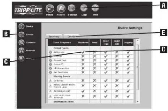
Click the "Settings" button2A at the top of the window.
Click the "Events" button at the left side of the window.
- Confirm that the "Battery Low" C in the "Shutdown" D column is checked.
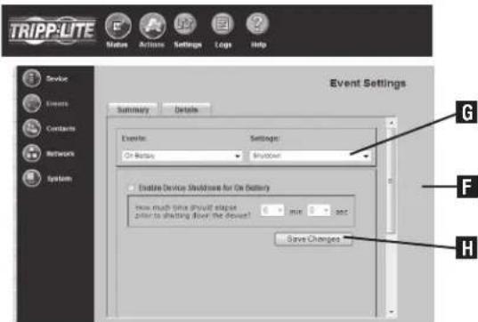
- Click the Details Tab E or double-click on the icon to access settings.
- From the Details page F, choose your preferred settings from the Settings drop down menu G and click the "Save Changes" button H
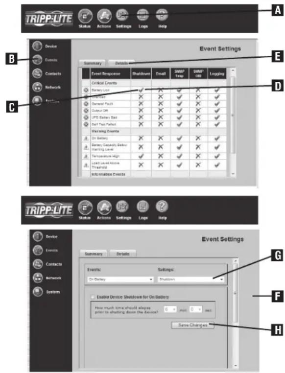
Figure 2-1: UPS System Shutdown Settings
2.2 Other Default Settings
Figure 2-2: Default SNMPWEBCARD Settings
| Setting Default Value Additional Information | ||
| IP Address Obtain via DHCP | 3.9 Settings > Network | |
| User Name and Password | User Name: admin Password: admin (For Version 12.04.0030 and Above) | 3.10 Settings > System |
| User Name: guest Password: guest | ||
| User Name: admin Password: [blank] (For Versions 12.03.0024 and 12.04.0019) | ||
| Telnet Access Enabled (S$H Access: Enabled) | 3.9 Settings > Network | |
| Web Access | Enabled (SSL Access: Disabled) | 3.9 Settings > Network |
| SNMP Access | Enabled for Version 12.04.0040 and above | 3.9 Settings > Network |
| Disabled for Previous Versions | ||
| Default SNMP Access for 12.04.0040 and above | ||
| Community Access Type Network Access SNMP Version | ||
| tripplite read/writeall v2c | ||
| public read only all v1 | ||
| Temperature High & Battery Low Event | Shut Down UPS System 2 Minutes After Event | 3.7 Settings > Events |
| E-mail Notification | Not Configured | 3.7 Settings > Events |
| SNMP Traps | Not Configured | 3.9 Settings > Network |
| Time | Use Onboard Clock (Set Manually) | 3.10 Settings > System |
| Event Logging | Enabled | 3.11 Logs > Events |
| Data Logging | Disabled | 3.12 Logs > Data |
| Ramp/Shed | Remain off / Remain on (not configured) | 5.0 Load Ramping and Shedding |
| SYSLOG | Disabled | 3.9 Settings > Network |
2.3 SNMP Configuration
SNMPWEBCARD allows a compatible UPS system or PDU to function as an SNMP-managed device on your network, using the SNMP agent and Management Information Base (MIB). The SNMP agent resides in the SNMPWEBCARD firmware and responds to standard SNMP commands (Get, Get Next and Set). It can also generate SNMP traps (messages). The MIB determines which parameters can be monitored and controlled. Two MIB files—Triplite.mib and RFC1628.mib—must be loaded on each Network Management Station that will monitor the managed device. (The files are provided on the CD-ROM included with the SNMPWEBCARD or network-enabled PDU. Consult your Network Management Station software documentation for instructions on how to import MIB files.)
3. Web Console
The Web console is the primary graphical user interface for the SNMPWEBCARD.
3.1 Opening the Web Console
Open a Web browser that supports frames, forms and Java. 1.
Type the IP address assigned to the SNMPWEBCARD or PDU into 2. the address field and press the enter key. (Refer to the printed manual for IP address assignment instructions.)
You should be prompted for a user name and password (Figure 3. 3-1). The default administrator user name is admin and the default password is admin.
After you enter the user name and password, the status page (Figure 4. 3-3) will appear in the browser window.
Note: Pages update automatically every 30 seconds. Reload/refresh a page manually to update sooner.
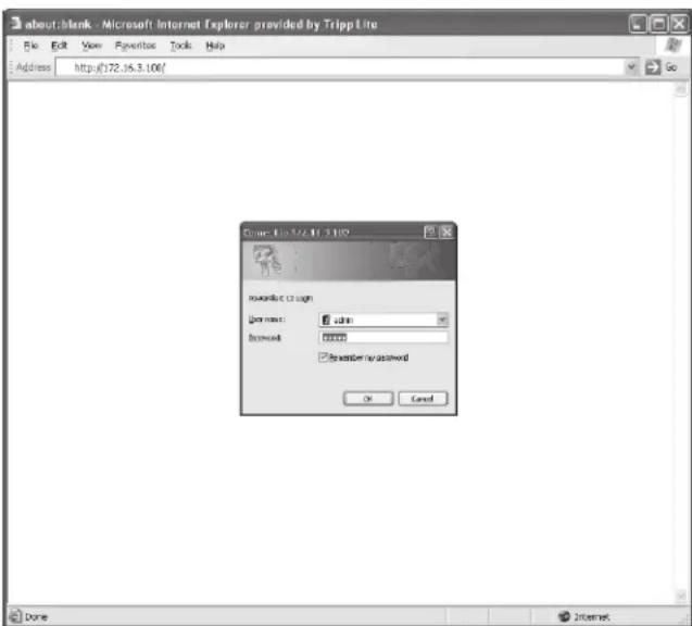
Figure 3-1: Web Console Login
3.2 Web Console Interface
Clicking the Tripp Lite logo A in the header opens Tripp Lite's Web site in a new browser window. The header also contains the menu buttons B, which are the main navigational icons of the console. Clicking a menu button reveals submenu buttons C on the left side of the console that are applicable to the selected menu button. When you click a menu or submenu button, the text changes from white to green.
Each submenu has an information section D that appears when the submenu is selected. The information section contains data, settings and/or controls. Several of the information sections are further divided into tabs E.
The alarm section F appears at the bottom of the console window regardless of which submenu is selected. If an alarm or other notification condition occurs, the alarm section will show the severity of the condition, the cause of the condition (such as "UPS on Battery") and the automatic response or recommended user response (such as "Prepare system for shutdown").
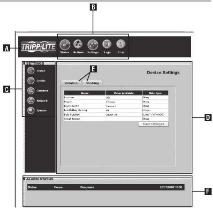
Figure 3-2: Console Interface Overview
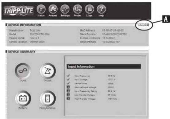
3.3 Status
Click the "Status" menu button to display the status page (Figure 3-3), which displays device information, device summary and alarm status. Four additional buttons within the window allow you to select information categories: input information, output information, battery information and miscellaneous information such as additional device information and system information. When you activate an information category, the button for that category changes from white to blue. The status of each information item is indicated by the icon next to the item.
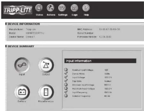
Figure 3-3: Status Page
3.3 Status (Continued)
RSS Feed
The RSS Feed feature was implemented to allow users to subscribe to the SNMPWEBCARD to view current alarm status, as well as event logs in the form of .XML, .TXT and .CSV files. This allows a user to quickly view status on the SNMPWEBCARD without requiring a login to each individual device.
- Click on the RSS symbol A.
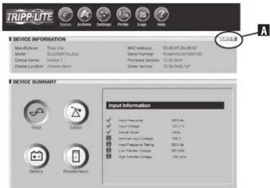
Figure 3-4: RSS Feed Screen
- Add the URL http://x.x.x.x:8080/digest.xml to the RSS reader or aggregator. Note: If the SNMPWEBCARD is configured to SSL mode, enter HTTPS instead of HTTP.
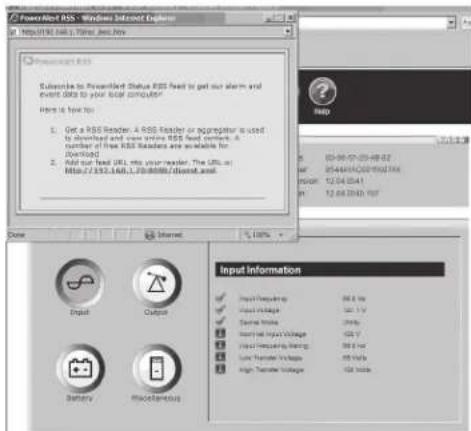
Figure 3-5: RSS Subscription
This is an example of the status screen viewed via the RSS reader:
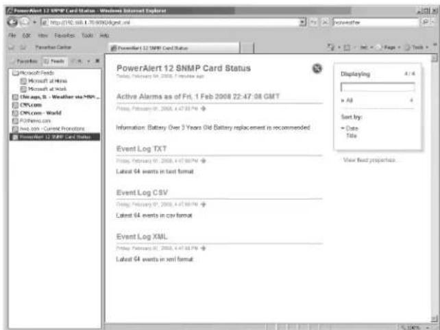
Figure 3-6: Status Screen
Dynamic Generation of Status Report
The SNMPWEBCARD's Web interface makes it possible to retrieve current alarm status through XML, text (TXT), or comma-delimited CVS file extensions. This feature can be used to integrate status information into proprietary management systems. To retrieve the file, enter the following URL: http://x.x.x.x/status.fileextension.Note: If the SNMPWEBCARD is configured to SSL mode, enter HTTPS instead of HTTP.
3.4 Actions > Control
Click the "Actions" menu button and the "Control" submenu button to display the Actions > Control page. Click the "Controls" tab (Figure 3-7) to see commands that you can execute immediately or schedule for automatic execution. To execute a command immediately, select it from the drop-down menu and click the "Execute" button. To schedule a command, select it from the drop-down menu, set the desired time and frequency parameters and click the "Schedule" button.
If the command you select from the drop-down menu has operational parameters that you can modify, they will be shown in the "Parameters" area. You can click the editable variables and type new values to change the settings for the command. If you plan to change the command parameters, you should change them before you execute the command or add it to the command schedule.
Available commands include "Reboot UPS," "Initiate Self-Test," "Cycle All Loads," "Cycle Load," "Turn Load Off," "Turn Load On," "Turn All Loads Off," and "Turn All Loads On". For a complete list of commands available for your device, refer to the drop-down menu.
Click the "Schedules" tab (Figure 3-8) to see a list of scheduled commands. To remove a scheduled command, check the box next to the command and click the "Delete Selections" button.
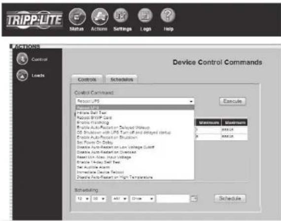
Figure 3-7:Actions > Control > "Controls"Tab
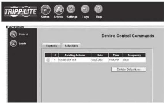
Figure 3-8:Actions Control > "Schedules"Tab
3.4.1 Actions > Control > Economy Mode
Economy Mode
When a SmartOnline UPS System operates in on-line mode, it continuously converts AC input power to DC (battery) power and converts DC power to regulated AC output power. Continuous double conversion produces ideal output, but does not provide maximum efficiency.
In Economy Mode (available on select models), the UPS system increases efficiency by implementing dynamic double conversion, which means it suspends or resumes double conversion automatically as the quality of input power changes. As long as input power quality is satisfactory, the UPS system suspends double conversion and operates with maximum efficiency. If input power quality deviates from the designated safe operating range, the UPS system resumes double conversion until input power quality improves.
You can turn Economy Mode on or off at any time, from any location. You can also schedule Economy Mode, allowing the UPS system to provide maximum protection during peak hours and maximum efficiency during off-peak hours.
Enabling Economy Modc:
To put a Tripp Lite SmartOnline UPS System into Economy Mode, go to the "Actions" menu button and the "Control" submenu button. Select either "Enable Economy Mode" or "Set Economy Mode", depending on the UPS. If the UPS has "Set Economy Mode", enter a "1" in the "Parameters-Value" field and then click the "Execute Command" button. On the front panel of the UPS system, the "LINE" and "LOAD" LEDs will illuminate green and the "BYPASS" LED will illuminate a solid yellow when the UPS system is in Economy Mode. Models with LCD display will indicate Economy Mode status in the LCD screen.
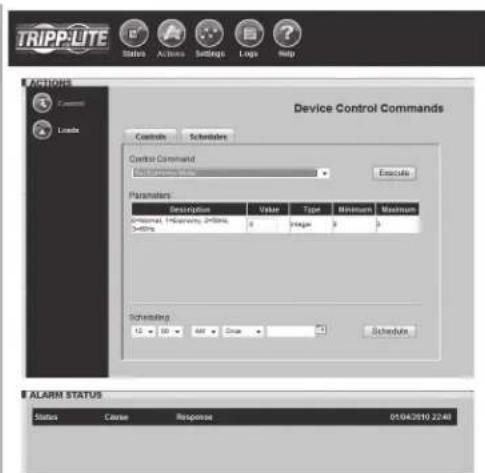
Figure 3-9: Actions > Control > "Controls" Tab > Set Economy Mode
3.4.1 Actions > Control > Economy Mode (Continued)
Disabling Economy Mode:
To put a Tripp Lite SmartOnline UPS System out of Economy Mode, go to the "Actions" menu button and the "Control" submenu button. Select either "Disable Economy Mode" or "Set Economy Mode", depending on the UPS. If the UPS has "Set Economy Mode", enter a "0" in the "Parameters-Value" field and then click the "Execute Command" button. On the front panel of the UPS system, the "LINE", "ONLINE", and "LOAD" LEDs will illuminate green.
3.5 Actions > Loads
Click the "Actions" menu button and the "Loads" submenu button to display the Actions > Loads page (Figure 3-10). You can control the outlets of the managed device by selecting the load and then clicking the appropriate "On," "Off" or "Cycle" button. The load of connected equipment is displayed as a percentage of maximum capacity, allowing you to see whether additional equipment can be added safely. (Load fluctuates with the power demands of connected equipment. It is prudent to limit the load to approximately 80% of maximum capacity in order to accommodate higher startup power demands and other increased power needs.)
If your device has controllable load banks, additional buttons allow you to control each load bank. (Each load bank consists of one or more outlets.) You can use the "Description" field to label the banks for easy reference. The main control buttons affect all outlets at once. Note: If the control buttons remain grayed out when a load is selected, this condition indicates the outlet is non-controllable.
Warning: The load controls start or stop the flow of electricity to your device's outlets. Make sure you know which equipment is connected to each load bank before attempting to use these controls. Check the outlet labels and/or test the load banks by plugging a circuit tester or small light into each outlet and observing the effects of the controls.
Note: On select PDUs and UPS systems it is possible to define logical outlet groups (groups of individual outlets) that can be controlled through a single command to turn ON/OFF or Cycle (see Figure 3-10a). This feature is only available on models that support Ramping and Shedding. See Section 5—Load Ramping and Shedding for more information. For select PDUs, support is available for individual outlet current and power information. If the PDU supports individual current and power information, additional columns (for Current and Power) will be displayed on the Loads page (see Figure 3-10b).
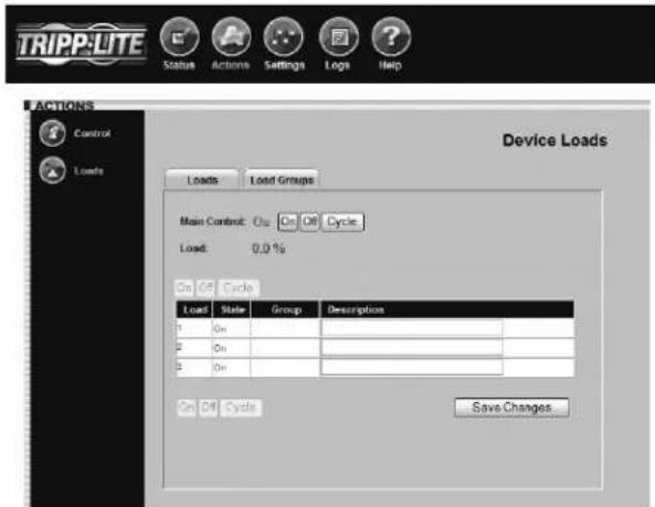
Figure 3-10:Actions > Loads Page

Figure 3-10a: Actions > Loads > Load Groups
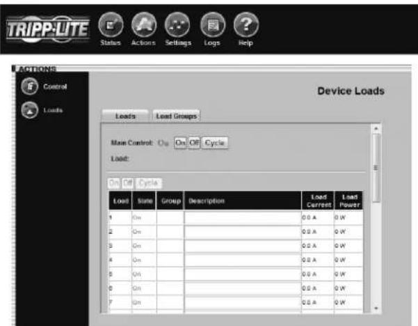
Figure 3-10b. Actions > Loads > Load Current/Power
3.6 Settings > Device
Click the "Settings" menu button and the "Device" submenu button to display the Settings > Device page (Figure 3-11). You can edit the device variables for the UPS system.
Note: Some UPS systems have fewer device variables; some have more. Some UPS systems will fill the "Serial Number" field automatically. The "Low Battery Warning" field is tied to the "Battery Capacity Below Warning" event.
See Section 5 - Load Ramping and Shedding for information about the "Ramping" and "Shedding" tabs. The tabs will only be accessible if the device supports these features.
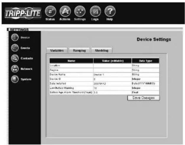
Figure 3-11: Settings > Device > Variables Tab
3.7 Settings > Events
Click the "Settings" menu button and the "Events" submenu button to access the Settings > Events page (Figure 3-12). The Settings > Events page allows you to configure responses to changes in operating and environmental conditions.
Events are divided into four categories: Critical, Warning, Information and Offline. Each event category has an icon associated with it. The icon will be displayed in the alarm status section of the console window (with other event information) when an event of that category occurs.
You can configure settings for several event types, including "On Battery" and "Battery Low." (Events vary by device.) See Figure 3-13 Settings > Events > Details Tab. You can configure several settings categories that specify actions to be executed when the selected event takes place:
"Shutdown"-Turns the device off after a specified period of time.
"Contact Notification"-Sends an e-mail to an e-mail address(es) in your contact list. (Requires an e-mail contact to be set. See Figure 3-14 Settings Contacts.)
"SNMP Trap Notification"- -Sends an SNMP trap to a specified IP address(cs) in your SNMP list. (Requires an SNMP contact to be set. See Figure 3-15 Settings > Contacts.)
- "Logging"-Enables logging for the selected event. Note: The Log can be accessed via Logs Menu.
"SNMP Set Notification"- Allows the device to perform an SNMP set on another SNMP-enabled device or application on the network, allowing the device or application to be notified when the event occurs. (Requires an SNMP contact to be set. See Figure 3-15 > Contacts.)
Check the "Status" box next to the event category to enable the option.
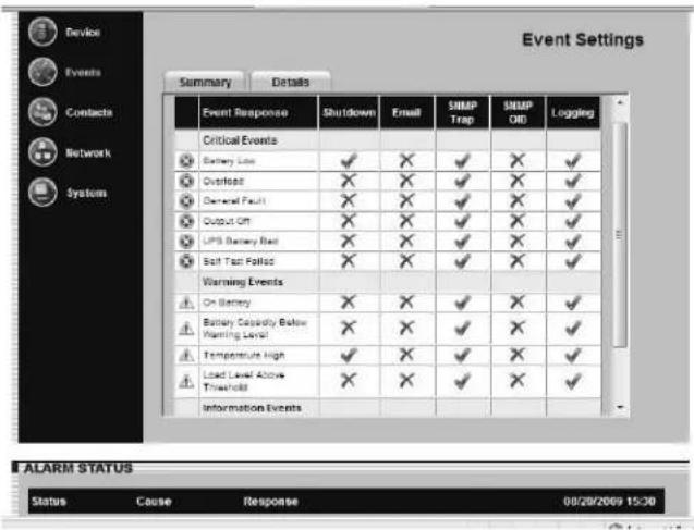
Figure 3-12: Settings > Events > Summary Tab
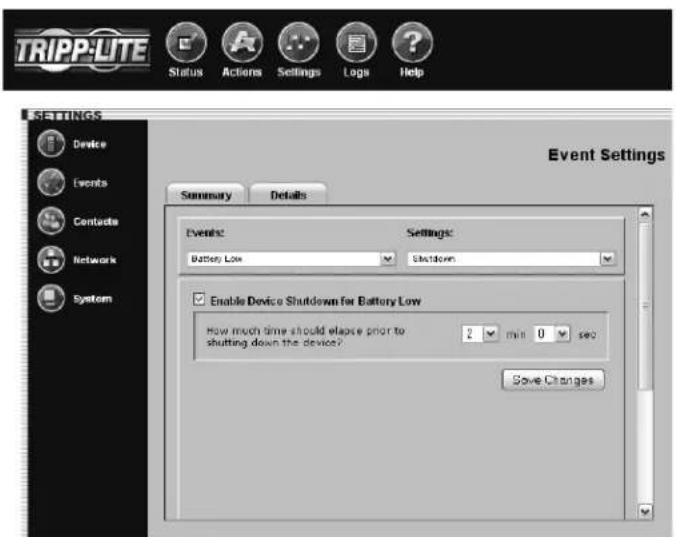
Figure 3-13: Settings > Events > Details Tab
3.8 Settings > Contacts
Click the "Settings" menu button and the "Contacts" submenu button to display the Settings > Contact Settings page.
The "Email" tab (Figure 3-14) shows a table of e-mail contacts. Before your SNMPWEBCARD can send e-mail notifications, you must enter e-mail server information and add at least one e-mail contact. Click the "SMTP Settings" button to enter the settings for your mail server. If you do not know the correct settings, contact your network administrator. Add a new email contact by clicking the "New" button and entering the information requested, and save. Test your settings by highlighting/selecting an email contact, then click the "Send Test Email" button.
Additional requirements for E-mail settings:
Enter a valid IP address or DNS name for the SMTP mail 1. server. (Using a DNS name requires valid DNS server settings. You will have the option to enter two: "Preferred DNS Server" and "Alternate DNS Server". See Section 3.9 Settings > Network.)
If SMTP authentication is required, obtain the authentication 2. information from your network Administrator (see Figure 3-14a).
The mail server must be set up to relay e-mail from the subnet 3. or IP address of the SNMPWEBCARD if SMTP Authentication is not being used.
The "To" and "From" addresses must be valid.4.
The "SNMP" tab (Figure 3-15) shows a table of SNMP contacts. Before your SNMPWEBCARD can send an SNMP trap or SNMP set to an IP address, you must add at least one SNMP contact. Add a new contact by clicking the "New" button and entering the information requested, and save. If you do not know the correct settings, contact your network administrator. (The standard port for SNMP set destinations is port 161. The standard port for SNMP trap recipients is port 162.)
Note: If adding an SNMP contact to be used with a SNMP Set Notification, use port 161 or the port number that the remote SNMP device can be accessed on. After adding Email and SNMP contacts, the user must set contacts for trap sending during events via Settings>Events (see 3.7 Settings>Events).
Note: You also need to configure and enable each event setting through the Settings>Events window before notifications can be sent to your contacts.
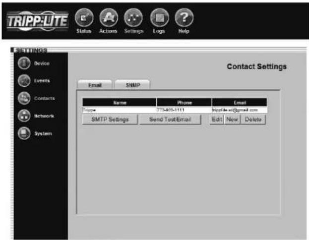
Figure 3-14: Settings > Contacts > Email Tab
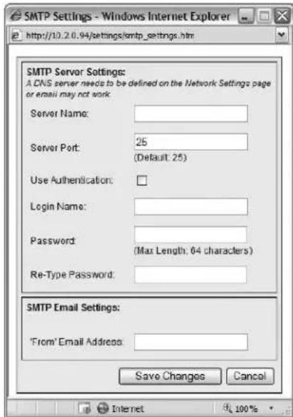
Figure 3-14a: Settings > Contacts > Email Tab > SMTP Server Settings
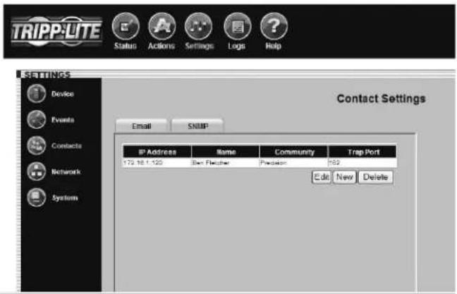
Figure 3-15: Settings > Contacts > SNMP Tab
3.9 Settings > Network
Click the "Settings" menu button and the "Network" submenu button to display the Settings > Network page.
Note: Any changes in the "TCP/IP" tab, "Telnet/SSH" tab or Web tab require the card to be rebooted.
The "TCP/IP" tab (Figure 3-16) contains several network settings:
"MAC Address" is the unique physical address of the SNMPWEBCARD and cannot be changed. The address is also printed on a label on the surface of the card. An extra label may be included.
"Host Name" is the unique name by which the SNMPWEBCARD is identified on the network. Host name is used to identify a particular host in various forms of electronic communication such as Web or email and is translated into an IP address via the Domain Name System (DNS) resolver for communication between devices over the network. Note: It is necessary to specify a DNS IP Address in the Settings > Network > TCP/IP Tab page and include these descriptions in the configuration of all pertinent Router/Switch networks.
"Domain Name" defines the local subnetwork.
"Boot Mode" defines whether the card has a static IP address (assigned manually) or a DHCP address (assigned automatically by a DHCP server on your network). DHCP is the default setting. (For instructions on assigning a static IP address via terminal mode, refer to the printed manual that came with your SNMPWEBCARD or PDU.)
"IP Address," "Network Mask" and "Default Gateway" are IP network settings that will either be assigned automatically or must be entered manually, depending on whether the card is set to use a static IP or DHCP. If you don't know the correct settings, contact your network administrator.
"Preferred DNS Server" and "Alternate DNS Server" are required only if you want to use domain names (such as mailserver.xyz.com) in addition to numeric addresses (such as 192.168.0.123).
"Ethernet Port Speed" defines the communication speed of the SNMPWEBCARD Ethernet port. By default, it will auto-negotiate in order to use the fastest speed that's compatible with your network equipment.
The "Telnet/SSH" tab (Figure 3-17) determines whether Telnet/SSII access is enabled or disabled. You can also set the Telnet/SSH port. (Default Settings: Telnet port is 23, SSII port is 22.) Note: Telnet/SSH access requires a user name and an admin password. Guest users do not have Telnet/SSH access. See Section 4.0 - Telnet/SSH Console for additional information about Telnet/SSII access. SSII is enabled by default.
(continued)
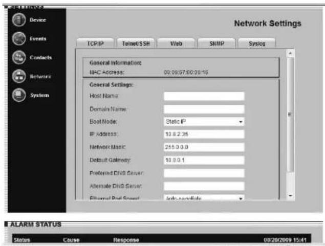
Figure 3-16: Settings > Network > TCP/IP Tab
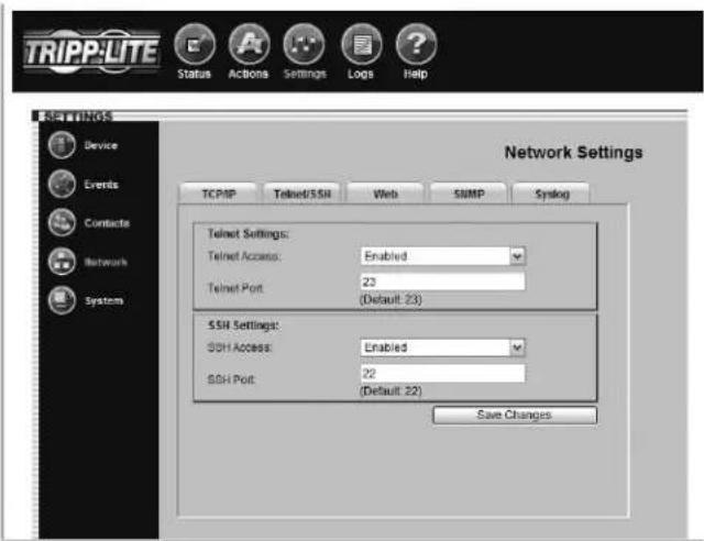
Figure 3-17: Settings > Network > Telnet/SSH Tab
3.9 Settings > Network (continued)
The "Web" tab (Figure 3-18) allows you to enable or disable Web browser access, choose the HTTP and/or HTTPS protocol and set the HTTP port.
HTTP (default setting) is the standard protocol used by Web browsers. HTTPS is a secure protocol that encrypts and decrypts data passed between the user and the SNMPWEBCARD. If HTTPS is selected, users can access the SNMPWEBCARD securely with HTTPS (https://x.x.x.x). If HTTP/HTTPS is selected, users can access the SNMPWEBCARD with either protocol. Note: HTTP and HTTPS can be globally or individually enabled/disabled.
Port 80 is the default HTTP port. The port can be changed in HTTP mode, but cannot be changed in HTTP/HTTPS mode. Port 443 is the HTTPS port and cannot be changed.
Note: Enabling HTTPS requires the card to reboot. This process may take several minutes. The default community name for SNMPWEBCARD firmware 12.04.0040 and above is triplite (read/write).
Access to the SNMPWEBCARD via SNMP can be configured to allow SNMP access (via a defined community string) to everyone, a range or a single IP by defining the appropriate subnet mask.
| SNMPv1 and SNMPv2 Address Subnet Community Access | |
| 192.168.1.1 (single) | 255.255.255.255 User-Defined User-Defined |
| 192.168.1.0 (range) | 255.255.255.0 User-Defined User-Defined |
| 192.168.0.0 255. | 255.0.0 User-Defined User-Defined |
| 192.0.0.0 255.0 | 0.0 User-Defined User-Defined |
| * (everyone) | 0.0.0 User-Defined User-Defined |
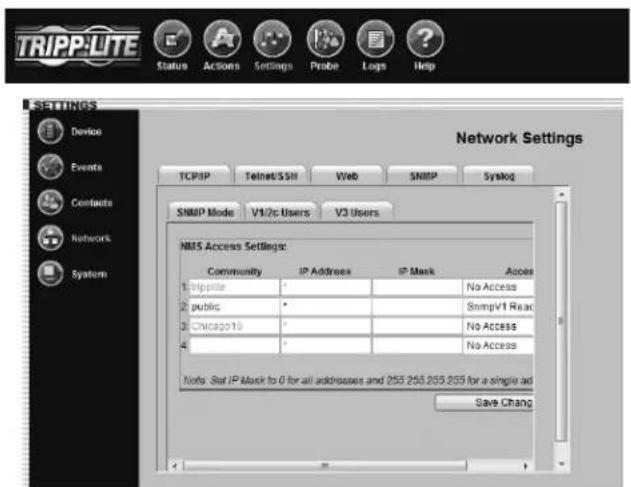
Figure 3-20: Settings > Network > SNMP > V1/V2c Users
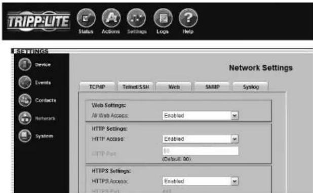
Figure 3-18: Settings > Network > Web Tab
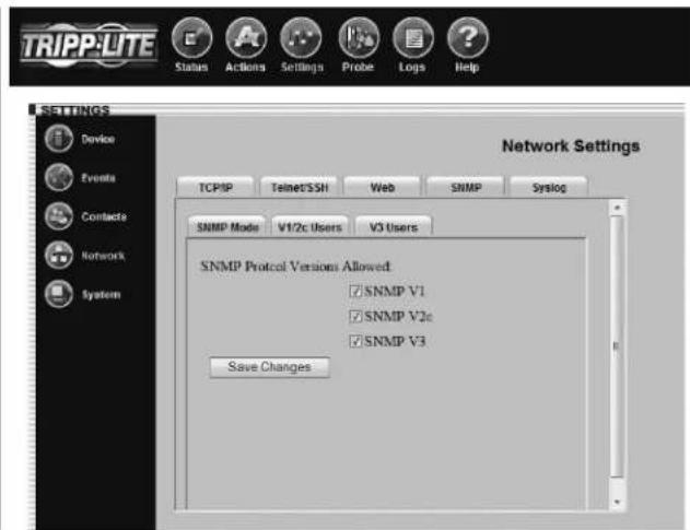
Figure 3-19: Settings > Network > SNMP > SNMP Mode
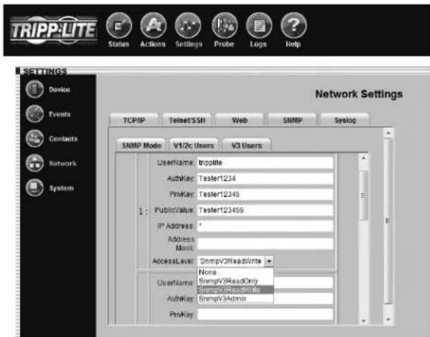
Figure 3-21: Settings > Network > SNMP > V3 Users
3.9 Settings > Network (continued)
As of Firmware version 12.04.0051, Tripp Lite's SNMPWEBCARD supports SNMPv3 Gets and Sets. SNMPv3 Traps are not supported. The SNMPWEBCARD SNMP Tab displays an additional three tabs to configure SNMP access:
A. SNMP Mode allows the user to configure what SNMP access is enabled or disabled. Note: Disabling SNMPv2 access will cause the SNMPWEBCARD not to function with Tripp Lite's PowerAlert Network Shutdown Agent or PowerAlert Network Management System.
B. V1/V2c Users Tab allows configuration of up to four community IDs.
C. V3 Users Tab allows configuration of up to four users. Tripp Lite's SNMPv3 implementation requires that Authentication and Privacy Passwords be configured.
| User Name | The identifier of the user profile. SNMP version 3 maps Gets, Sets and Traps to a user profile by matching the user name of the profile to the user name in the data packet being transmitted. A user name can have up to 32 ASCII characters. |
| Authentication Passphrase | A phrase of 8 to 32 ASCII characters that verifies that the Network Management System (NMS) communicating with this device through SNMPv3 is the NMS it claims to be, that the message has not been changed during transmission, and that the message was communicated in a timely manner, indicating that it was not delayed and that it was not copied and sent again later at an inappropriate time. |
| Privacy Passphrase | A phrase of 8 to 32 ASCII characters that ensures the privacy of the data (by means of encryption) that a Network Management System (NMS) is sending to this device or receiving from this device through SNMPv3. |
| Authentication Protocol The Tripp Lite implementation of SNMPv3 supports only MD5 authentication. | |
| Privacy Protocol | The Tripp Lite implementation of SNMPv3 supports only DES as the protocol for encrypting and decrypting data. |
| Public Value | A field provided to enter a username/password hint for SNMPv3 Admin users. This SNMPv3 value is part of the SNMPv3 UsrmUserTable. |
| IP Address A field provided to enter the information found in the “Address” column in the table on p. 11. | |
| Mask A field provided to enter the information found in the “Subnet” column in the table on p. 11. | |
IMPORTANT NOTE: There are a total of four unique SNMP access IDs across all SNMP versions. Therefore, if you have two SNMPv1/2 communities, you can then have two SNMPv3 users.
SYSLOG
SYSLOG is a protocol that allows a machine to send event notification messages across IP networks to event message collectors - also known as SYSLOG servers. Up to 4 SYSLOG servers may be defined by either IP address or hostname (Figure 3-22). Hostnames require that a DNS (Domain Name System) server be configured on the TCP/IP tab. Once configured, any event, setting change or action will trigger a message to be sent to the SYSLOG server for logging.
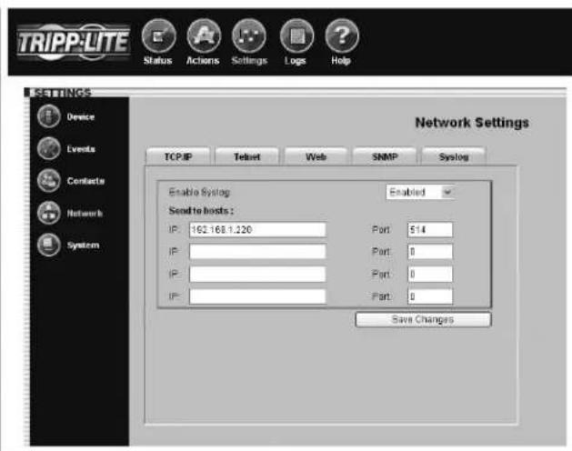
Fig. 3-22: SYSLOG
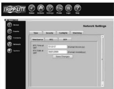
3.10 Settings > System
Click the "Settings" menu button and the "System" submenu button to display the Settings > System page.
The SNMPWEBCARD has a real-time clock with a backup battery that keeps the clock running when the card is powered off. The "ConfigFile" and three "Time" tabs (Figures 3-23 through 3-26) allow you to set the date and time manually or to define a Network Time Protocol server for periodic network time synchronization. The time zone can also be specified. If you don't know the correct Network Time Protocol server settings, contact your network administrator.
The "Security" tab (Figure 3-27) allows you to define usernames and set passwords for three user levels: guest, manager and administrator (admin). Guest users have read-only access and do not have telnet access. Manager users have similar rights to Admin users, however, they are not allowed to change security settings. Admin users have read/write access, which means that they can control the SNMPWEBCARD and change its settings. Tripp Lite recommends defining passwords for both user levels.
Note: For firmware version 12.04.0019 and 12.03.0024, the default admin password is blank. For firmware version 12.04.0030 and above, the default admin password is admin.
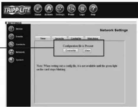
Write Configuration/View Configuration
The SNMPWEBCARD can maintain a copy of its current configuration as a backup in the event of system problems or to configure other SNMPWEBCARDs via FTP.
To generate a configuration file (paconfig.ini), select the "Write Config" button at the bottom of the page. This file can also be viewed and saved to your computer A by clicking the "view" button. You will be prompted with a login screen, at which time you may enter Administrator username and password.
To distribute the configuration file to other SNMPWEBCARDs (12.04.0040 or above), FTP to the SNMPWEBCARD's IP address. In binary mode, "PUT" the configuration file (paconfig.ini) to the SNMPWEBCARD, then close the FTP session. When the SNMPWEBCARD reboot, it will operate according to the new configuration file. Note: The admin password will be required to view or download the configuration file.
A
Fig. 3-23: Settings > System > ConfigFile
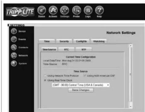
Fig. 3-24: Settings > System > Time > TimeSource
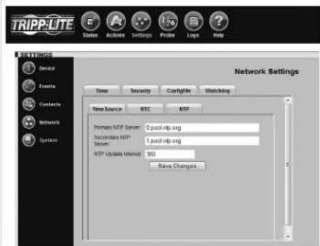
Fig. 3-25: Settings > System > Time > NTP
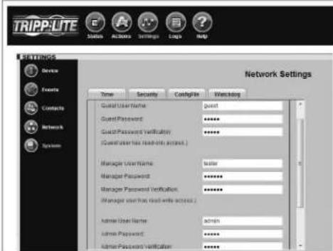
Fig. 3-26: Settings > System > Time > RTC Figure 3-27: Settings > System > Security Tab
Watchdog Tab
The Watchdog tab provides the user the ability to set up timers that will reboot the card automatically if the Watchdog trigger is reached. This provides a mechanism to maximize the uptime/ accessibility of the SNMPWEBCARD. The Watchdog tab allows enabling/disabling of either the Ping probe or NTP probe.
Primary Ping Target: IPv4 address/hostname (requires DNS settings to be configured).
Secondary Ping Target: IPv4 address/hostname (requires DNS settings to be configured) (optional).
Ping Probe Interval: Time in minutes before retry.
Probe Tries Before Fail: The number of attempts to ping the primary and secondary IP addresses before the SNMPWEBCARD assumes there is a problem and reboot itself.
The SNMPWEBCARD will continue to reboot until it is successfully able to ping the primary or secondary IP address.
Primary NTP Target: · IPv4 address (requires DNS settings to be configured).
Secondary NTP Target: IPv4 address/hostname (requires DNS settings to be configured) (optional).
NTP Probe Interval: Time in minutes before retry. Probe Tries Before Fail: The number of attempts to get time from the primary and secondary NTP addresses before the SNMPWEBCARD assumes there is a problem and reboots itself.
The SNMPWEBCARD will continue to reboot until it is successfully able to get time from either the primary or secondary IP address.
Note: The Watchdog tab is applicable for Firmware version 12.04.0051 and above.
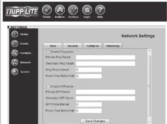
Fig. 3-28: Settings > System > Watchdog
3.11 Logs > Events
Click the "Logs" menu button and the "Events" submenu button to display the Logs > Events page (Figure 3-29). All events are logged here with a date, time and description. Each event also displays an icon that identifies its status: normal, critical, warning, information or offline.
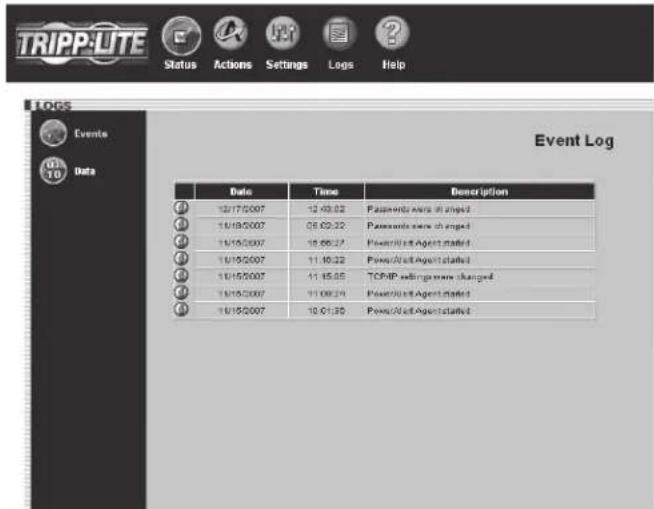
Figure 3-29: Logs > Events Page
3.12 Logs > Data
Click the "Logs" menu button and the "Data" submenu button to display the Logs > Data page (Figure 3-30). Data logging is disabled by default. You can enable data logging and save changes by entering a logging interval between 1 and 60. When data logging is enabled, all data fields and their current value are logged. You can export the data log to a .CSV file by right-clicking the "Export Data Log" link and choosing "Save Target As..." or "Save Link As..." from the pop-up menu. Note: Only 250 data entries at a time will be stored. The option to clear the Data Log is also available. Simply click the "Clear Data Log" button.
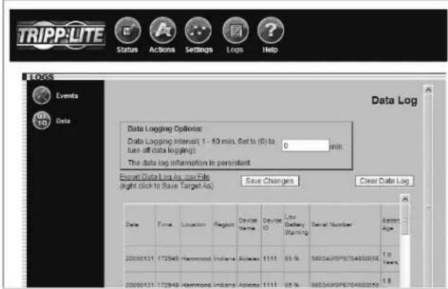
Figure 3-30: Logs > Data Page
3.13 Help
Click the "Help" menu button to open a PDF that contains the most recent version of the SNMPWEBCARD User's Guide.
4. Telnet/SSH Console
Most of the monitoring and control features available in the Web console (see Section 3 - Web Console) are also available in the telnet and/or SSH console. Accessing the SNMPWEBCARD through the telnet console is ideal for mobile or resource-limited platforms.
Accessing the Telnet Console
Open a telnet client and connect to the IP number of the SNMPWEBCARD. At the login prompt, enter the admin user name and password. (Telnet access must be enabled and an admin password must be defined. Guest users do not have telnet access.) After a successful login, you'll see the telnet console's main menu (Figure 4-1).
The Telnet Console Interface
The telnet console uses a menu-driven, text-based interface. It has most of the same menus and submenus as the Web console, but they are arranged differently. Several submenus that were previously grouped below "Settings" now appear at the top level, and instead of appearing at the top level, the "Status," "Actions," "Settings" and "Logs" menus are accessible under the "Devices" menu. You'll see those menu choices after selecting your device, along with information about the device (Figure 4-2). Note: You can also select an ENVIROSENSE temperature/humidity and alarm monitoring device if one is present.
The functional menu hierarchy of the telnet console interface is shown in Figure 4-3.
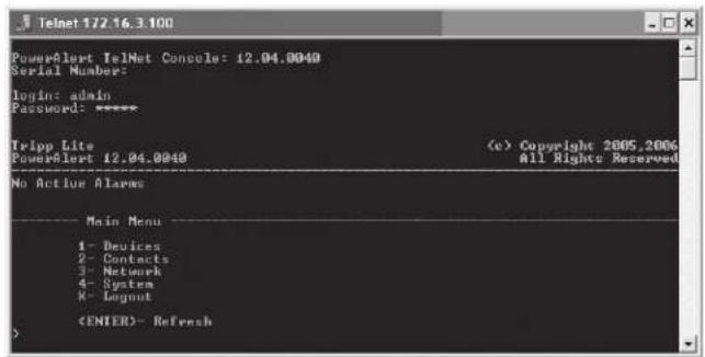
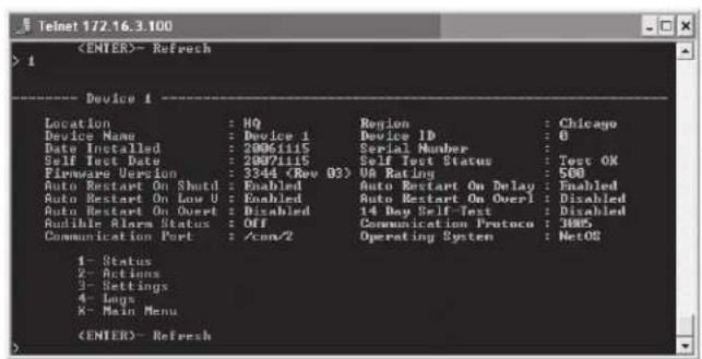
Figure 4-I: Telnet Console Main Menu
Figure 4-2: Telnet Console Device Submenu
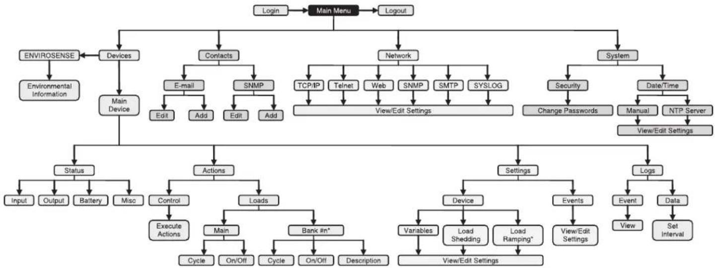
Figure 4-3: Telnet Console Menu Hierarchy
5. Load Ramping and Shedding
Click the "Settings" menu button and the "Device" submenu button to display the Settings > Device page. If your device supports load ramping and shedding, the "Ramping" tab and/or "Shedding" tab (Figure 5-1) will be available.
The "Ramping" and "Shedding" tabs each contain a table of the load segments available for your device. Each load segment has a "Description" field, an "Action" field and a "Delay" field. The "Description" field allows you to enter a note about the equipment connected to the load segment. The "Action" field allows you to configure the load ramping or shedding behavior by choosing from the possible actions listed in the drop-down menu. The "Delay" field allows you to enter the delay (in seconds) before the specified action is performed. After entering the desired values, click the "Save Changes" button to make the values active. Ramping sequences are applied when AC input power is switched on. Shedding sequences are applied when AC input power is lost, increasing the battery backup runtime available for supported equipment. You can disable load shedding by setting all actions to "Remain On." You can disable load ramping by setting all actions to "Remain Off."
Load ramping and load shedding require a Tripp Lite UPS system or PDU with switchable load banks (banks of one or more outlets that can be switched on and off remotely, independent of other outlets). A device that has switchable load banks can be classified as an autonomous device or a non-autonomous device, which determines its load ramping and load shedding characteristics (Figure 5-2).
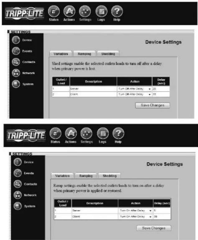
Figure 5-1: Settings > Device > Shedding & Ramping Tabs
Figure 5-2: Autonomous and Non-Autonomous Device Characteristics
| Custom Load Ramping Custom Load Shedding | ||||
| ConfigurationExecution | ConfigurationExecution | |||
| Autonomous Device | Requires SNMPWEBCARD or PowerAlert. | Functions without SNMPWEBCARD or PowerAlert. | Requires SNMPWEBCARD or PowerAlert. | Functions without SNMPWEBCARD or PowerAlert. |
| Non-Autonomous Device | Not supported. Not supported. Requires SNMPWEBCARD. Requires SNMPWEBCARD. | |||
An autonomous device can execute stored load shedding and load ramping configurations independent of an SNMPWEBCARD or PowerAlert. Configuration of an autonomous UPS system requires PowerAlert or an SNMPWEBCARD (disconnect the SNMPWEBCARD network cable before attempting to use an autonomous UPS system's RS-232 serial port). Configuration of an autonomous PDU requires an SNMPWEBCARD (the card is preinstalled in "NET" models). Figure 5-3 lists autonomous devices that are currently available.
Non-autonomous devices require an SNMPWEBCARD for configuration and execution of a custom load shedding sequence. Non-autonomous devices do not support custom load ramping. UPS systems that have switchable load banks are non-autonomous devices unless they are listed in Figure 5-3.
Note: Load ramping and shedding can also be configured through the telnet console. (Select the first menu option "1- Devices" from the Main Menu, then select the first device from the Device List menu, then select the third menu option "3- Settings". From the Settings menu, select the second menu option "1- Device". From the Device Settings menu, select the second menu option "2- Shedding" for shedding configuration or the third menu option "3- Ramping" for ramping configuration.)
Figure 5-3: Autonomous Devices
| Part Number Series Number | |
| SMART1500CRMXL All | |
| SM2200RMDVTAA All | |
| SM2200RMXL2UP All | |
| SM2200RMXL2UTAA All | |
| SMART2200CRMXL All | |
| SMART2200RM2U AGSM7501 | |
| SMART2200RMXL2U | AGSM6803, AGSM7109 |
| SMART2600RM2U AGSM6907 | |
| SM3000RMNAFTA AGSM7090 | |
| SM3000RMXL2UTAA All | |
| SMART3000CRMXL All | |
| SMART3000RM2U | AGSM6908, AGSM6909 |
| SMART3000RMOD2U | All |
| SMART3000RMXL2U All | |
| SMX2200RT2UTAA | All |
| SMX2200XLRT2U | AGSM7145 |
| SMX3000RT2UTAA | All |
| SMX3000XLRT2U | AGSM7144 |
| SU3000RTXL2U | All |
| SUINT3000RTXL2U | All |
| Switched PDU models | All with “NET” suffix |
| Switched PDU models | All with “PDU3VS” prefix |
6. Troubleshooting
If you encounter a problem:
Confirm that the SNMPWEBCARD is turned on.
Check all connections and confirm that they are secure.
Refer to the following list of problems and implement any recommended solutions.
If the problem persists after trying the recommended steps, contact
Tripp Lite Technical Support.
| Problem Possible Solution | |
| The IP address of the SNMPWEBCARD is unknown. | If your network's DHCP server assigned an IP address to the SNMPWEBCARD, contact your network administrator to discover the IP address assigned to the card or view it during terminal session at boot-up. You'll need to know the MAC address of the SNMPWEBCARD. If your network does not use DHCP, or if you need to assign a static IP address for another reason, follow the instructions for assigning a static IP address via terminal mode configuration. Refer to the printed manual that came with your SNMPWEBCARD or PDU for more information. |
| Unable to perform SNMP get operations. | Check the SNMP settings of the SNMPWEBCARD (see 3.9 Settings > Network). The IP address and community name of the device or application trying to perform the SNMP get operation must be entered in "NMS Access Settings" with "Read Only" or "Read/Write" permission. |
| Unable to perform SNMP set operations. | Check the SNMP settings of the SNMPWEBCARD (see 3.9 Settings > Network). The IP address and community name of the device or application trying to perform the SNMP set operation must be entered in "NMS Access Settings" with "Read/Write" permission. |
| Unable to receive traps at your management station. | Check the SNMP settings of the SNMPWEBCARD (see 3.9 Settings > Network). The IP address and community name of the management station must be entered in "NMS Access Settings" with "Read/Only" or "Read/Write" permission. Also check trap recipient settings in Contacts menu and Events menu. |
| Unable to use autodiscovery to find the agent from your management station. | Check the SNMP settings of the SNMPWEBCARD (see 3.9 Settings > Network). The IP address and community name of the management station must be entered in "NMS Access Settings" with "Read/Write" permission. Versions below 12.04.0040 are not supported. |
| The HTTP interface displays an error message: Action Fail. | If the previous command is not yet finished, another command cannot be executed. You must wait until the previous command has finished. |
| SNMPWEBCARD e-mail notifications are not working. | Before your SNMPWEBCARD can send e-mail notifications, you must enter e-mail server information and add at least one e-mail contact in the Settings > Contacts > Email Tab (Figure 3-14). Click the "SMTP Settings" button to enter the settings for your local mail server. If you do not know the correct settings, contact your network administrator. Add a new e-mail contact by clicking the "New" button and entering the information requested in the pop-up window. Test your settings by clicking the "Send Test Email" button. Additional requirements for E-mail settings: Enter a valid IP address or DNS name for the SMTP mail server. (Using a DNS name requires valid DNS server settings. See 3.9 Settings > Network.) The mail server must not require authentication.1. The mail server must be set up to relay e-mail from the subnet or IP address of the 2. SNMPWEBCARD. The "To" and "From" addresses must be valid.3. 4. A DNS IP must be specified in the Settings > Network > TCP/IP tab page. Note: You also need to configure and enable each event setting through the Settings > Events page before notifications can be sent to your contacts. |
7. Technical Support
Before contacting Tripp Lite Technical Support, refer to Section 6 - Troubleshooting for possible solutions. If you are still unable to resolve the problem, you can reach Tripp Lite Technical Support here:
www.triplite.com/support
E-mail: techsupport@tripplite.com
Tripp Lite has a policy of continuous improvement. Specifications are subject to change without notice.

1111 W. 35th Street, Chicago, IL 60609 USA
www.triplite.com/support
Guiá del usuario
SNMPWEBCARD
Version de Firmware 12.04.0048
1111 W. 35th Street, Chicago, IL 60609 USA
www.triplite.com/support
www.triplite.com/support
Correo electrónico: techsupport@tripplite.com
1111 W. 35th Street, Chicago, IL 60609 USA
www.triplite.com/support
1111 W. 35th Street, Chicago, IL 60609 USA
www.triplite.com/support
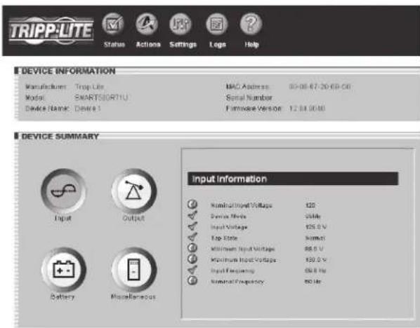
Figure 3-3: Page de I'etat
3.3 État (suite)
Fil de syndication
3.5 Actions > Charges
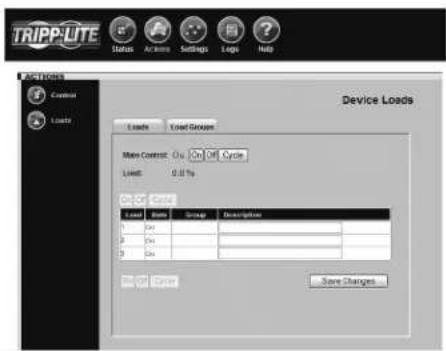
Figure 3-10: Page Actions > Charges
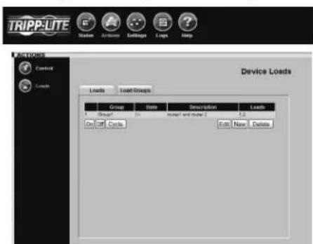
Figure 3-10a: Actions > Charges > Groupes de charges
7. Assistance technique
www.triplite.com/support
Courriel: techsupport@tripplite.com
1111 W. 35th Street, Chicago, IL 60609 USA
www.triplite.com/support
PykoBoDCTBO NOIb3OBaTeJa
SNMPWEBCARD
BepnMkponporpammbi 12.04.0048
1111 W. 35th Street, Chicago, IL 60609 USA
www.triplite.com/support
Copyright © 2010 Tripp Lite. Bcc TopROBHe MapKn HbHIOTe HckIOHTeHbHO C6cTBcHnOCTbIO CBOHX bAaTeHbTcER.
1.BBedeHne
SNMPWEBCARD 10000000000000000000000000000000000000000000000000000000000000000000000000000000000000000000000000000
*KapmaSNMPWEBCARD npedyamnoe ena ypaenaeux upeumnebx bdoxax pachpedeeneu numan (PDU), oboaaneue nuoou komopnx codepcum cunoeo "MN" uau "NET".
1.1 CnCTeMHbIe Tpe6oBaHna
CncreMa HbII Tripp Lite HIN 6IOK PDU c coBmecTHMbIM pa3bcmOM IIN pHINIAJIeKHOCTeI
Cetb Ethernet, KOTOPAIIIOJIePKBaERIPOIOKONTCP/IP
OHa n3 cIeIyIoumH oxuui IyIaIeHHoro KOHTPOJI H ynpabHeHHra:
CnCTema cctcBoro ynpabnnn PowerAlert
- Ctaunu ynpabJeHHa cetbHa 6a3e SNMP (Haipmep, HP OpenView)
Be6-6payep, KOTOpbI IIOUepKBAeT PpeimbI, foPmH JYaTM (HaipnMep, Microsoft *Internet Explorer *7.0 HIN CTapue)
CraIapTnHa nporpaMa telnet
ToIbkoIOKOHPHpyHpOBAHnBpeKHeTePmHaHa:
Iporpamma 3mynann Tepmna (Hapnpc, HyperTerminal)
KoHbTePco CBOO0DHBIM IOCIEIOBATEIbHbIM IOPROM DB9
Ipeynepoohnne:He pekamouemc Hncno1b0aamb mnoobopyoohnue 6 npnoeunx uckyccmennzo noodepokunu knnneodmehocnn, de aonkauanoo obopyoanaum moncm enaabmbocmaohky oboypoanaum nooepomau knehedemchmucn noa hnaumn ha eao bnonacnomb n u npfkekmnocmb. He nnoiuyime 3mnpnnpop 6 cpdx c codepkaenue neko 6cnlaaneux cmecem obbehaanuaaouco maacaae 6ooydym, kucnopodn an jakcuab ztoa.
2. YctaHOBka N KOHcHypaCmN
HctpykuHH no yctaHOke aapataHoro oecneeneHH 6a3OBOMy KOHpypOBAHNO CHCTeMH IIpeCTABHEH B neaTHOH BEpCHN pyKOBOCTBA NO EKJIpyATAHH, BXoJIIEB B KOMIIeKT NocTABKN KapTH SNMPWEBCARD HIN 6to paePceTCHN PHTAHNN (PDU).TO pyKOBOCTBO TAKKe HaxOHTeR HA KOMIAKT-HeKe H3 KOMIIeKTaIOCTABKN, cro MoKHO 3arpy3Hb c Be-caiHa www.triplite.com/support/manuals/.
2.1Hactpoikn no ymouaHIO dIy OTKIOUeHnCNCTeMbI N5P
BoBpemIpepebBOBIOJDAeEKeTPO3HePNPepBaHPteHbOcKoHfHy pOBaHHJIe HAcPTpOH SNMPWEBCARD BIOJIOJIT OTKIOChNE CnCTEMBI HBII YpeC3 DBe MmTEIOJyEHNI CHIIA O IH3KOM 3apae6aTapeH. 3IO IOBOBET ChTeMBI IIOBEcEHNBATM KMcHMAIBHO BO3MOKHoe BPem ApoBTiIOKIOHOUHORO OobpyOBAHH. TOb6I HMeHTY cTaHOBHNO yMOJAAHHIO BIVIOIHNTB cIeIyoHIne DeNCTBHI, NOKaAHHHe Ha PNC.2-1:
C IIOOMOIBo Be6-bpayepa OTKpbTb OKHO KOHCOIN PowerAlertIJI KAPTB1. SNMPWEBECARD (HnctpykTNn npncdeHn Ha pnc.3.1 OkHo Bxoda be6-KOHcIN).
HaKaTbKHOHcyA《Settings》(HaCTpoTHKn)BBCpxHCnHaCThOKHa.
HaKaTb KOnKy 8 «EvCns» (co6HTHa), KOToPAI NOBHTc c JcBOI CTOpOHi OKHa.
4.Y6eHHbC, YOYcTAHOBHEn dMakOK C «Battery Low» (HH3KnI yPOBeHb 3apaa batapeH) B KOJOHOKe D «Shutdown» (OTKIOUHeHne).
5.IpeHnHaBkAkyE《Details》(IOpObHmceCbeEHn)IINIBaKbI HcKHyTB3aOKIIOCTyNAHacTPOiKaM.
6. Hc tpaHnIe F «Details» (noJpo6HbIe CBeJeHHa) BbIbpaTb
PpeIIOHTeJIbIe IacTPOKIN H3 BbIIaIIOIero McIIO G nIaKaTb
KHOIKy H «Save Changes» (coXpaHIn bI3MeHeHHa).
Puc.2-1:Haempoiku omknouenmu cunmemb HII
3.3 CtaTyc (npodoxhenue)
RSS-kaHai
Bo3MOKHOCTB RSS-KaHaTa 6bHa pcaH3OBaHa DToTO, Yo6b HIOJIb3OBAteH MIOI HoIIHcAHTbC H a HOUYeHHe O1 SNMPWEBCARD HIOPOCMOTPA TekyIero COCTOBHH ABAHINHBx H3BeUeHn, a TAKKE KypHaJa Co6bHn B HnDe qaiIOB φOpMaTt. XML, .XTN .CSV. 310 IO3BOJET IOJIb3OBATe.Ho6bTPO IIOPCMOTpe CTATyC uepe3 KapTy SNMPWEBCARD 6e3 Heo6xoHIMOCHT BxOJITB B KaKaJoE OtJeBHoe ycTpoHCTBO.
- HaxatachmBoT RSS A
Puc.3-4:Kpan RSS-kanana
www.triplite.com/support
E-mail: techsupport@tripplite.com
II. INTKHKA KOMHAAHH Tripp Lite coctoHT B HeIpepbBHom yCOBepweHCTBOAHHH. TexHHueckHe xapakTepcHCTKN MOYt H3MeHHTbC8e3 yBeJOM.IEHN.

1111 W. 35th Street, Chicago, IL 60609 USA
www.triplite.com/support

- Introduction
- System Requirements
- Installation and Configuration
- Default UPS System Shutdown Settings
- Other Default Settings
- SNMP Configuration
- Web Console
- Opening the Web Console
- Web Console Interface
- Status
- Status (Continued)
- RSS Feed
- Dynamic Generation of Status Report
- Actions > Control
- Actions > Control > Economy Mode
- Economy Mode
- Enabling Economy Modc:
- Actions > Control > Economy Mode (Continued)
- Disabling Economy Mode:
- Actions > Loads
- Settings > Device
- Settings > Events
- Settings > Contacts
- Settings > Network
- Settings > Network (continued)
- SYSLOG
- Settings > System
- Write Configuration/View Configuration
- Watchdog Tab
- Logs > Events
- Logs > Data
- Help
- Telnet/SSH Console
- Accessing the Telnet Console
- The Telnet Console Interface
- Load Ramping and Shedding
- Troubleshooting
- Technical Support
- Guiá del usuario
- SNMPWEBCARD
- État (suite)
- Fil de syndication
- Actions > Charges
- Assistance technique
- PykoBoDCTBO NOIb3OBaTeJa
- 1.BBedeHne
- CnCTeMHbIe Tpe6oBaHna
- YctaHOBka N KOHcHypaCmN
- 2.1Hactpoikn no ymouaHIO dIy OTKIOUeHnCNCTeMbI N5P
- CtaTyc (npodoxhenue)
- RSS-kaHai
Brand : Tripp Lite
Model : SNMPWEBSOLOHV
Category : Network adapter