
T100001TST - Cable stripper Tripp Lite - Free user manual and instructions
Find the device manual for free T100001TST Tripp Lite in PDF.

| Product Type | Cable Crimp/Stripper with Built-in Tester RJ11/RJ12/RJ45 |
| Brand | Tripp Lite |
| Model | T100001TST |
| Main Functions | Cuts, strips (round and flat cables), crimps modular connectors 8P8C, 6P6C, 4P4C, built-in UTP/STP cable tester with LED display |
| Power Supply | 1 x 6V A544 1/2 AA battery or 4 x LR44 button cell batteries |
| Test Range | Up to 183 m (600 ft) with removable remote unit |
| Cable Types Tested | UTP, STP, local network cables up to 12 mm diameter |
| Test Indicators | LED indicators: shielding, pairs 1-2, 3-6, 4-5, 7-8, short circuit, reversal, split pair, miswiring |
| Cutting Slot | Yes, at the back of the tool |
| Round Stripping Slot | Yes, for 12 mm round cable |
| Flat Stripping Slot | Yes, between the double blades |
| Crimping Slots | 4-pin (rear), 6-pin, 8-pin |
| Handles | Ergonomic, non-slip, with locking |
| Remote Unit | Removable, attaches to handle for storage |
| Battery Replacement | Removable cover plate |
| Maintenance and Cleaning | Wipe with a dry cloth; no oil or lubricant |
| Safety | Do not use for life support equipment; keep out of reach of children |
| Warranty | 1 year (limited warranty) |
| General Information | Designed to create and test custom network cables; compliant with WEEE directive |
Frequently Asked Questions - T100001TST Tripp Lite
User questions about T100001TST Tripp Lite
0 question about this device. Answer the ones you know or ask your own.
Ask a new question about this device
Download the instructions for your Cable stripper in PDF format for free! Find your manual T100001TST - Tripp Lite and take your electronic device back in hand. On this page are published all the documents necessary for the use of your device. T100001TST by Tripp Lite.
USER MANUAL T100001TST Tripp Lite
RJ11/RJ12/RJ45 Cable Crimper/Stripper with Built-In Tester
Model: T100-001-TST
Espanol 13 • Français 25 • Русский 37
PROTECT YOUR INVESTMENT!
Register your product for quicker service and ultimate peace of mind. You could also win an ISOBAR6ULTRA surge protector—a \$100 value!
www.tripplite.com/warranty


1111 W. 35th Street, Chicago, IL 60609 USA www.tripplite.com/support
Copyright © 2018 Tripp Lite. All rights reserved.
Package Includes
- T100-001-TST
- Owner's Manual
Product Features
- All-in-one crimping tool efficiently cuts and strips LAN cables up to 12 mm in diameter
- Multifunctional crimping tool creates all 8P8C, 6P6C and 4P4C plug types
- Built-in UTP/STP cable tester quickly and accurately identifies wiring faults in newly crimped or existing in-wall LAN cables up to 600 ft. (183 m) with detachable remote unit
- Ergonomic design with non-slip handles for secure grip
- Perfect for creating custom design cables
Operation
Opening / Closing the Tool
To open the tool handles, simply squeeze the handles together and release. To lock the handles in place, gently squeeze the handles together (one or two clicks) and release.
Operation
Cutting Cable
A single blade for cutting cable is located on the back of the tool. To use, insert the desired cable length into the slot labeled “CUT”. To cut the cable, squeeze the handles together until the cable cleanly separates.
Stripping Flat Cable
On the same side of the tool as the double blades, insert the cable between the blades. Squeeze the handles together to score each side of the cable, then pull off the jacket.
Stripping Round Cable
Insert the cable into the slot labeled “12MM ROUN CABLE”. Squeeze the handles together and rotate the tool around the cable to score the jacket. Pull off the jacket.
Crimping Connectors
Once the jacket has been stripped from the cable, insert the freestanding cable wires into the appropriate modular connector plug type. Next, insert the plug into the tool's corresponding 4-Pin (located on the back), 6-Pin, or 8-Pin slot. Squeeze the handles to crimp.
Operation
Testing Uninstalled Cables
When testing uninstalled patch cables, the remote unit can remain attached to the base of the main unit's handle. Connect one end of the cable to be tested to the main unit. Connect the other end of the cable to the remote unit. Push the “TEST” button to initiate the test. Note the LEDs present to determine the cable’s wiring status.
Testing Installed Cables
When testing installed patch cables, detach the remote unit from the main unit's base to allow for room-to-room testing. Using a jumper cable (not included), connect the remote unit to the wall jack or patch panel to be tested. Using a second jumper cable (not included), connect the main unit to the other wall jack or patch panel. Push the “TEST” button to initiate the test. Note the LEDs present to determine the cable’s wiring status.
Once testing is completed, the remote unit will securely snap into the base of the handle for easy storage and transport.
Note: This product is designed to test cable lengths up to 600 ft./183 m.
Cable Test Results
Pass Indicators:
Shield
Green SHIELD LED indicates the shield on the cable is correctly and continuously wired through the modular plug termination.
Standard Wiring
Four green LEDs on pairs 1-2, 3-6, 4-5, and 7-8 indicate all four pairs are terminated correctly.
Fail Indicators:
A flashing green LED indicates which wire pair(s) have a fault. A solid red LED in the FAIL section will indicate which fault(s) are detected. Multiple flashing green LEDs or solid red LEDs indicate multiple pairs and/or multiple faults.
Short
A short circuit condition exists.
Open
An open circuit condition exists. There is no "OPEN" LED indicator. OPENS are displayed as an unlit LED. See DEBUG Example #2 as reference.
Cable Test Results
Miswire
Indicates the improper assignment of one or more individual wire pairs to its pins for the wiring schemes tested. The tester checks T568A, T568B, 10Base-T and Token Ring configuration.
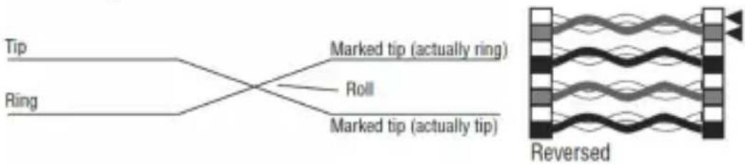
Reversal
Reverse wiring means the pin for one wire in a pair is connected to the opposite pin for the pair in the remote jack.
flowchart
graph LR
    A["Tip"] --> B["Marked tip (actually ring)"]
    C["Ring"] --> B
    B --> D["Roll"]
    B --> E["Marked tip (actually tip)"]
    F["Reversed"] --> G["Waveform with wavy lines"]
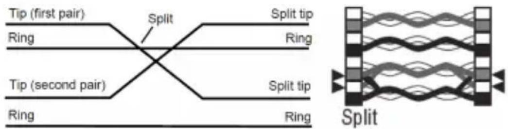
Split Pairs
Split pairs occur when the tip (positive conductor) and ring (negative conductor) of two twisted pairs are interchanged.
flowchart
graph LR
    A["Tip (first pair)"] --> B["Ring"]
    B --> C["Split"]
    C --> D["Ring"]
    E["Tip (second pair)"] --> F["Ring"]
    F --> G["Split tip"]
    G --> H["Ring"]
    I["Split"] --> J["Ring"]
    J --> K["Split tip"]
Note: The T100-001-TST will check a fault condition in the above order before detecting other fault conditions. The detection and indication of a fault is handled on a one-per-test basis. Once a fault is corrected, it is recommended the cable be tested again for other faults.
DEBUG Mode
Debug mode allows you to identify which cable pairs have a wiring fault. This mode cycles through each cable pair, displaying a test result for one pair at a time. From the series of LED indicators, the failed pair and fault condition can be identified. In Debug mode, the first short flash on the PAIR LEDs display the pair under test. The second long flash on the PAIR LEDs is the destination of the test.
To DEBUG:
- Press and hold the "TEST" button unit all cable pairs have been tested.
- The PAIR identification LEDs and the FAIL LEDs work together in series to identify which pair(s) are incorrectly wired.
- If a series of two green LEDs (one short and one long) display as a pair, then that pair is wired correctly.
- A green PAIR LED followed by a red LED in the FAIL section reveals which pair is incorrectly wired and the fault associated with that pair.
- Debug mode continues to cycle through each cable pair until the "TEST" button is released, termintating the test.
DEBUG Mode
DEBUG Example #1:
The cable fault is a short on Pair 3-6, the Debug mode LED series is as follows:
- Pair 1-2 will flash green-green as a good pair.
- Pair 3-6 will flash green on the PAIR LED followed by a red on the SHORT LED.
- Pair 4-5 will flash green-green as a good pair.
- Pair 7-8 will flash green-green as a good pair.
Note: SHIELD LED will not illuminate if the cable being tested is a UTP cable.
DEBUG Mode
DEBUG Example #2:
The following are examples of potential LED sequences on Pair 1-2 and possible fault conditions for that pair only.
| 1st Short Flash | 2nd Long Flash | Red Fault LEDs Fault Condition | |
| 1-2 1-2 No | Red LED Good | Pair | |
| 1-2 None No | Red LED Open | Condition | |
| 1-2 1-2 Reversal Pair Reversed | 1-2, 2-1 | ||
| 1-2 1-2 Short Pin 1 Shorted to | Pin 2 | ||
| 1-2 7-8 Miswire Pin 1 - Pin 7, | Pin 2 - Pin 8 | ||
| 1-2 7-8 Miswire, | Reversal | Pin 1 - Pin 8, Pin 2 - Pin 7 | |
| 1-2 1-2 Split Pair Wire from 1-2 | twisted with wire from another pair, continuity good | ||
Note: The above examples are for Pair 1-2 only. Similar LEDs would relate to other pairs under test (short flash).
Battery Replacement
- Remove the cover plate to change the batteries.
- Remove old batteries.
- Install a new 6-volt A544 1/2AA size battery or 4 LR44 Button Cell batteries.
- Slide cover plate back into place.
Warranty and Product Registration
1-Year Limited Warranty
Tripp Lite warrants its products to be free from defects in materials and workmanship for a period of one (1) year from the date of initial purchase. Tripp Lite's obligation under this warranty is limited to repairing or replacing (at its sole option) any such defective products. To obtain service under this warranty, you must obtain a Returned Material Authorization (RMA) number from Tripp Lite or an authorized Tripp Lite service center. Products must be returned to Tripp Lite or an authorized Tripp Lite service center with transportation charges prepaid and must be accompanied by a brief description of the problem encountered and proof of date and place of purchase. This warranty does not apply to equipment, which has been damaged by accident, negligence or misapplication or has been altered or modified in any way.
EXCEPT AS PROVIDED HEREIN, Tripp Lite MAKES NO WARRANTIES, EXPRESS OR IMPLIED, INCLUDING WARRANTIES OF MERCHANTABILITY AND FITNESS FOR A PARTICULAR PURPOSE. Some states do not permit limitation or exclusion of implied warranties; therefore, the aforesaid limitation(s) or exclusion(s) may not apply to the purchaser.
EXCEPT AS PROVIDED ABOVE, IN NO EVENT WILL Tripp Lite BE LIABLE FOR DIRECT, INDIRECT, SPECIAL, INCIDENTAL OR CONSEQUENTIAL DAMAGES ARISING OUT OF THE USE OF THIS PRODUCT, EVEN IF ADVISED OF THE POSSIBILITY OF SUCH DAMAGE. Specifically, Tripp Lite is not liable for any costs, such as lost profits or revenue, loss of equipment, loss of use of equipment, loss of software, loss of data, costs of substitutes, claims by third parties, or otherwise.
Warranty and Product Registration
PRODUCT REGISTRATION
Visit www.triplite.com/warranty today to register your new Tripp Lite product. You’ll be automatically entered into a drawing for a chance to win a FREE Tripp Lite product!*
* No purchase necessary. Void where prohibited. Some restrictions apply. See website for details.
WEEE Compliance Information for Tripp Lite Customers and Recyclers (European Union)
Under the Waste Electrical and Electronic Equipment (WEEE) Directive and implementing regulations, when customers buy new electrical and electronic equipment from Tripp Lite they are entitled to:
- Send old equipment for recycling on a one-for-one, like-for-like basis (this varies depending on the country)
- Send the new equipment back for recycling when this ultimately becomes waste
Use of this equipment in life support applications where failure of this equipment can reasonably be expected to cause the failure of the life support equipment or to significantly affect its safety or effectiveness is not recommended.
Tripp Lite has a policy of continuous improvement. Specifications are subject to change without notice.


1111 W. 35th Street, Chicago, IL 60609 USA www.tripplite.com/support
1111 W. 35th Street, Chicago, IL 60609 EE UU www.tripplite.com/support
flowchart
graph LR
    A["Tip"] --> B["Marked tip (actually ring)"]
    C["Ring"] --> B
    B --> D["Roll"]
    B --> E["Marked tip (actually tip)"]
    F["Reversed"] --> G["Waveform with wavy lines"]
Pares Divididos
1111 W. 35th Street, Chicago, IL 60609 EE UU www.tripplite.com/support
1111 W. 35th Street, Chicago, IL 60609 USA www.tripplite.com/support
Miswire (mauvais raccordement)
flowchart
graph LR
    A["Tip"] --> B["Marked tip (actually ring)"]
    C["Ring"] --> B
    B --> D["Roll"]
    B --> E["Marked tip (actually tip)"]
    F["Reversed"] --> G["Waveform with wavy lines"]
1111 W. 35th Street, Chicago, IL 60609 USA www.tripplite.com/support
1111 W. 35th Street, Chicago, IL 60609 USA
www.tripplite.com/support
flowchart
graph LR
    A["Tip"] --> B["Ring"]
    B --> C["Marked tip (actually ring)"]
    B --> D["Roll"]
    B --> E["Marked tip (actually tip)"]
    F["Reversed"] --> G["Waveform with wavy lines"]
Разделение пар
natural_image
Abstract diagram with wavy lines and blocks, no text or symbols present1111 W. 35th Street, Chicago, IL 60609 USA www.tripplite.com/support
18-01-155 93-37F4_revA
- RJ11/RJ12/RJ45 Cable Crimper/Stripper with Built-In Tester
- PROTECT YOUR INVESTMENT!
- Package Includes
- Product Features
- Operation
- Opening / Closing the Tool
- Cutting Cable
- Stripping Flat Cable
- Stripping Round Cable
- Crimping Connectors
- Testing Uninstalled Cables
- Testing Installed Cables
- Cable Test Results
- Pass Indicators:
- Shield
- Standard Wiring
- Fail Indicators:
- Short
- Open
- Miswire
- Reversal
- Split Pairs
- DEBUG Mode
- To DEBUG:
- DEBUG Example #1:
- DEBUG Example #2:
- Battery Replacement
- Warranty and Product Registration
- 1-Year Limited Warranty
- PRODUCT REGISTRATION
- WEEE Compliance Information for Tripp Lite Customers and Recyclers (European Union)
- Pares Divididos
- Miswire (mauvais raccordement)
- Разделение пар
Brand : Tripp Lite
Model : T100001TST
Category : Cable stripper