HCT16 - Doorbells LIFT-MASTER - Free user manual and instructions
Find the device manual for free HCT16 LIFT-MASTER in PDF.
| Product Type | Vertical lift vehicle barrier/gate actuator |
| Brand | LIFT-MASTER |
| Model | HCT16 |
| Usage Class | II (commercial/general access), III (industrial/limited access), IV (restricted access) |
| Main Power Supply | 120 V AC, 4 A or 240 V AC, 2 A |
| Backup Power Supply | 2 batteries 12 V DC, 7 Ah each |
| Service Voltage | 24 V DC |
| Rail Dimensions | 597 cm long (HCT16) |
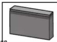
| Motor Housing Dimensions | Approximately 44.5 x 60.3 x 19.1 cm |
| Maximum Barrier/Gate Weight | 453.6 kg (1000 lb) |
| Maximum Barrier/Gate Width | 6.0 m (22 ft) |
| Travel Speed | Default 20.3 cm/s (8 in/s); rapid opening 27.9 cm/s (11 in/s) |
| Daily Cycle Capacity | Up to 500 cycles per day (HCT16) |
| Operating Temperature | -20 °C to 60 °C (-4 °F to 140 °F) |
| Main Functions | Automatic opening/closing, built-in obstacle detection, limit programming, close timer, MyQ and Security+ 2.0 compatibility, built-in alarm, constant pressure release function |
| Maintenance | Monthly reversal system test, battery check, inspection of entrapment protection devices |
| Safety | Mandatory entrapment protection devices (photoelectric sensors, detection edges), obstacle contact reversal, emergency stop, dual entrapment alarm |
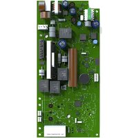
| Spare Parts Available | 7 Ah batteries, logic boards, carriage, rail, cable assemblies, remote controls, sensors, etc. Repair by authorized technician recommended |
| General Information | 5-year limited commercial warranty. Installation and maintenance by a duly trained technician. Compliance with UL 325 and ASTM F2200 standards. |
Frequently Asked Questions - HCT16 LIFT-MASTER
User questions about HCT16 LIFT-MASTER
0 question about this device. Answer the ones you know or ask your own.
Ask a new question about this device
Download the instructions for your Doorbells in PDF format for free! Find your manual HCT16 - LIFT-MASTER and take your electronic device back in hand. On this page are published all the documents necessary for the use of your device. HCT16 by LIFT-MASTER.
USER MANUAL HCT16 LIFT-MASTER
Access installation and technical support guides or register this product
• THIS PRODUCT IS TO BE INSTALLED AND SERVICED BY A TRAINED TECHNICIAN ONLY.
- This model is for use on vehicular passage gates or commercial doors ONLY and not intended for use on pedestrian passage gates.
• Install the operator at least 8 feet (2.4 m) above the floor.
- This model is intended for use in Class II, III and IV vehicular trolley gate or commercial door applications.
- Visit LiftMaster.com to locate a professional installing dealer in your area.
- This gate/door operator is compatible with MyQ® and Security+ 2.0® accessories.

text_image
LiftMaster PHOTOREGISTER® HCTDCULTECH- Take a photo of the camera icon including the points ( ).
- Send it in by texting the photo to 71403.

LiftMaster
300 Windsor Drive
Oak Brook, IL 60523
LiftMaster®
ELITE SERIES®
TABLE OF CONTENTS
SAFETY 2
Safety symbol and signal word review 2
Usage Class ....3
UL325 Entrapment Protection Requirements 3
Safety Installation Information 4
Gate Construction Information 5
INTRODUCTION 6
Carton Inventory 6
Operator Specifications 7
Overview of Typical Installation 8
INSTALLATION 9
Important Installation Instructions 9
Step 1 Connect Rail to Operator ....10
Step 2 Install Vented Plug ....11
Step 3 Determine Location for Operator ....11
Step 4 Mount the Operator ....12
Step 5 Install Entrapment Protection ....13
WIRING 15
Step 6 Power Wiring ....15
Step 7 Connect Batteries and Attach Antenna....16
ADJUSTMENT 17
Limit and Force Adjustment 17
Obstruction Test 18
Remote Controls (Not Provided) 20
LiftMaster Internet Gateway (Not Provided) 21
Erase All Codes 21
Erase Limits 21
Constant Pressure Override (CPO) 21
Gate Hold Open Feature 21
To Remove and Erase Monitored Entrapment Protection Devices .....21
Limit Setup with a Remote Control 22
OPERATION 23
Gate/Door Operator Setup Examples 23
Control Board Overview 24
Reset Button 25
Operator Alarm 25
Adjsutable Open Speed 25
Remote Control 25
Manual Disconnected 26
ACCESSORY WIRING 27
External Control Devices 27
External Reset Button 27
Miscellaneous Wiring 28
EXPANSION BOARD 30
Expansion Board Overview 30
Auxiliary Relay 1 and 2 ....31
Wiring Accessories to the Expansion Board 32
MAINTENANCE 33
Important Safety Instructions 33
Maintenance Chart 33
Batteries....33
TROUBLESHOOTING 34
Diagnostic Codes 34
Diagnostic Codes Table 35
Control Board LEDs 37
Troubleshooting Chart 38
WIRING DIAGRAM 41
REPAIR PARTS 42
ACCESSORIES 43
WARRANTY 45
SAFETY
Safety Symbol and Signal Word Review
When you see these Safety Symbols and Signal Words on the following pages, they will alert you to the possibility of Serious Injury or Death if you do not comply with the warnings that accompany them. The hazard may come from something mechanical or from electric shock. Read the warnings carefully.
When you see this Signal Word on the following pages, it will alert you to the possibility of damage to your gate and/or the gate operator if you do not comply with the cautionary statements that accompany it. Read them carefully.
IMPORTANT NOTE:
- BEFORE attempting to install, operate or maintain the operator, you must read and fully understand this manual and follow all safety instructions.
- DO NOT attempt repair or service of your gate operator unless you are an Authorized Service Technician.
WARNING
MECHANICAL
WARNING
ELECTRICAL
CAUTION

WARNING: This product can expose you to chemicals including lead, which are known to the State of California to cause cancer or birth defects or other reproductive harm. For more information go to www.P65Warnings.ca.gov.
SAFETY
Usage Class
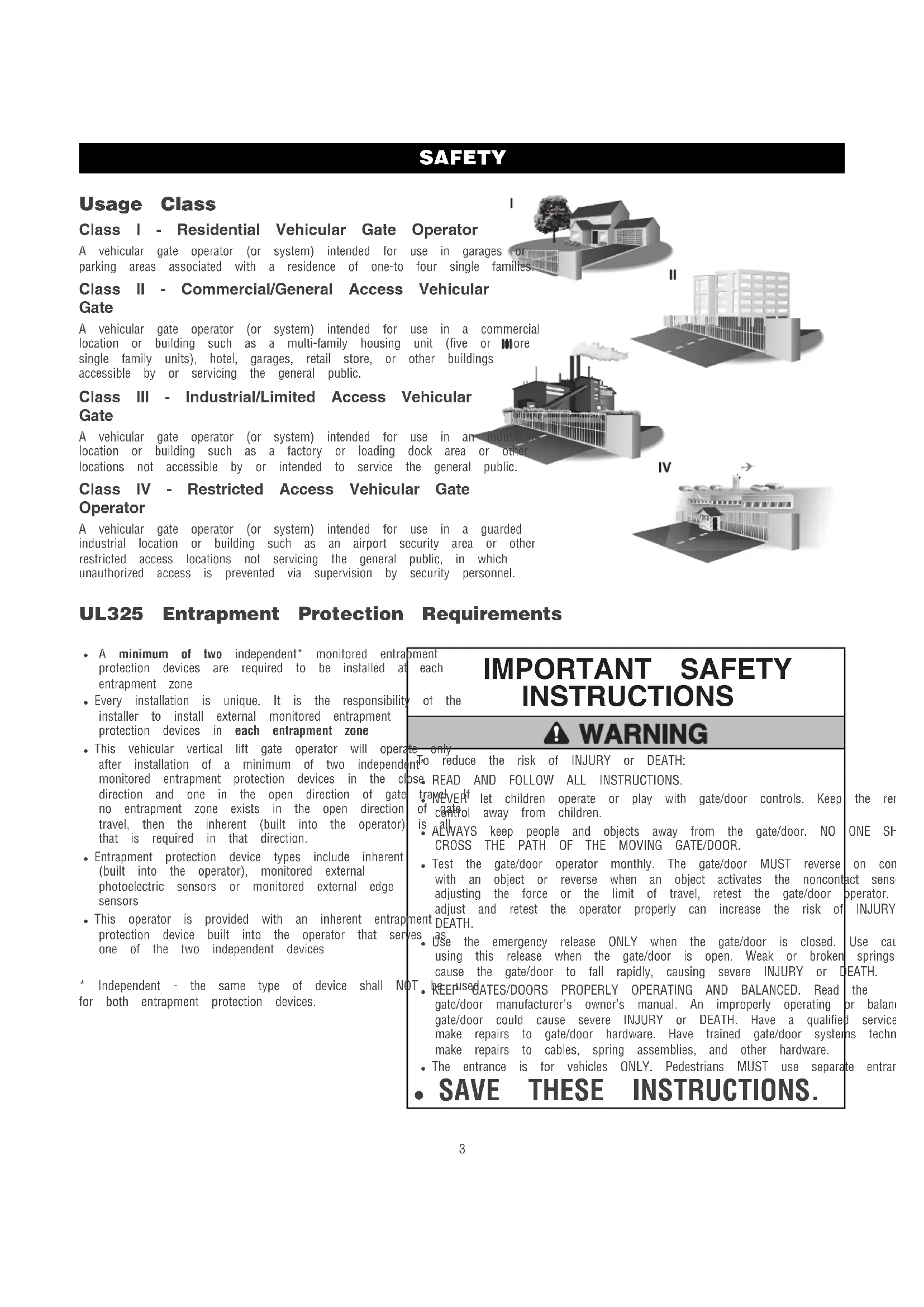
Class I - Residential Vehicular Gate Operator
A vehicular gate operator (or system) intended for use in garages or parking areas associated with a residence of one-to four single families.
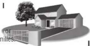
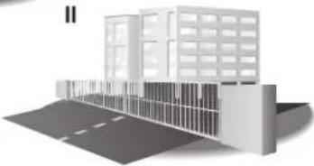
Class II - Commercial/General Access Vehicular Gate
A vehicular gate operator (or system) intended for use in a commercial location or building such as a multi-family housing unit (five or more single family units), hotel, garages, retail store, or other buildings accessible by or servicing the general public.
Class III - Industrial/Limited Access Vehicular Gate
A vehicular gate operator (or system) intended for use in an indoor location or building such as a factory or loading dock area or other locations not accessible by or intended to service the general public.
Class IV - Restricted Access Vehicular Gate Operator
A vehicular gate operator (or system) intended for use in a guarded industrial location or building such as an airport security area or other restricted access locations not servicing the general public, in which unauthorized access is prevented via supervision by security personnel.
|
natural_image
Illustration of a modern house with a tree and open ground, no visible text or symbols||
natural_image
3D architectural rendering of a modern building with windows and adjacent road (no text or symbols visible)
natural_image
Illustration of an industrial factory with smokestacks emitting vapor, surrounded by partial text fragments (no legible signage)IV
natural_image
Illustration of a building with parked cars and an airplane, no visible text or symbolsUL325 Entrapment Protection Requirements
- A minimum of two independent* monitored entraprotection devices are required to be installed at entrapment zone
- Every installation is unique. It is the responsibility of the installer to install external monitored entrapment protection devices in each entrapment zone
- This vehicular vertical lift gate operator will operate after installation of a minimum of two independent monitored entrapment protection devices in the cl direction and one in the open direction of gate no entrapment zone exists in the open direction travel, then the inherent (built into the operator) that is required in that direction.
- Entrapment protection device types include inherent (built into the operator), monitored external photoelectric sensors or monitored external edge sensors
- This operator is provided with an inherent entrap protection device built into the operator that serves one of the two independent devices
oment
each
of the
1 + u1 - 1 = ( 1 + u) u1 < 1 = u
m = 311
The image is too blurry to recognize any text content.
To
m
OSE
tr
of
is
•
[Non-Text]
•
01
[Non-Text]
[Non-Text]
mon
hen
es
[Non-Text]
To
tr
of
is
•
•
01
[Non-Text]
[Non-Text]
hen
es
[Non-Text]
* Independent - the same type of device shall NOT for both entrapment protection devices.
[Non-Text]
T
1.
[Non-Text]
IMPORTANT SAFETY INSTRUCTIONS
WARNING
nto reduce the risk of injury of DEATH.
ose READ AND FOLLOW ALL INSTRUCTIONS.
[Non-Text]
T
1.
[Non-Text]
[Non-Text]
[Non-Text]
[Non-Text]
The Ground Truth image displays a single, solid horizontal line. According to Rule 2 (UNDERSCORE & LINE RULES), this is a stylistic or background line, not a placeholder underscore. Therefore, the OCR result must ignore it and output nothing or only meaningful text. The provided OCR content is "____", which consists of four underscores. This is an incorrect interpretation of the line as a placeholder, violating the rule that stylistic lines must be ignored. The OCR has hallucinated underscores where none should exist based on the GT's visual context. Hence, the OCR result is inconsistent with the Ground Truth.
•
(五)本说明仅供参考。
●
1 + u1 - 1 = ( 1 + u) u1 < 1 = u
[Non-Text]
[Non-Text]
[Non-Text]
[Non-Text]
[Non-Text]
[Non-Text]
[Non-Text]
[Non-Text]
[Non-Text]
[Non-Text]
[Non-Text]
[Non-Text]
[Non-Text]
[Non-Text]
[Non-Text]
SAFETY
Safety Installation Information
- Vehicular gate systems provide convenience and security. Gate SystemStop and/or Reset (if provided separately) must be located are comprised of many component parts. The gate operator line-of-siglone of the gate. Activation of the reset control shall in component. Each gate system is specifically designed for an individual operator to start. application.
-
A minimum of two (2) WARNING SIGNS shall be installed, or
-
Gate operating system designers, installers and users must take a side of the gate where easily visible. One must be installed account the possible hazards associated with each individual wall mounted control. application. Improperly designed, installed or maintained systems. Can a gate operator utilizing a non-contact sensor: create risks for the user as well as the bystander. Gate systems design a reference owner's manual regarding placement of non-contact and installation must reduce public exposure to potential hazards. Sensor for each type of application. See Install Entrapment
-
A gate operator can create high levels of force in its function Protection section. component part of a gate system. Therefore, safety features must be incorporated into every design. Specific safety features include: such as when a vehicle trips the sensor while the gate
-
Edges Sensors (contact)
• Guards for Exposed Rollers
• Photoelectric Sensors - Screen Mesh
- Vertical Posts
• Instructional and Precautionary Signage
- Install the gate operator only when:
a. The operator is appropriate for the construction and the class of the gate.
b. All openings shall be designed, guarded or screened to in. (102 mm) diameter sphere from passing through the anywhere in the gate.
c. All exposed pinch points are eliminated or guarded, and is supplied for exposed rollers.
-
The operator is intended for installation only on gates used vehicles. Pedestrians must be supplied with a separate access. The pedestrian access opening shall be designed to promote usage. Locate the gate such that persons will not come in the vehicular gate during the entire path of travel of the v
-
The gate must be installed in a location so that enough clearance is supplied between the gate and adjacent structures when opening and closing to reduce the risk of entrapment. Swinging gates shall not open into public access areas.
-
The gate must be properly installed and work freely in both directions prior to the installation of the gate operator.
-
Permanently mounted access controls intended for users to activate, must be located at least 6 feet (1.8 m) away from any moving part of the gate and where the user is prevented from reaching over, under, around or through the gate to operate the controls. Outdoor or easily accessible controls shall have a security feature to prevent unauthorized use. Exception: Emergency access controls only accessible by authorized personnel (e.g. fire, police) may be placed at any location in the line-of-sight of the gate.
must be Care shall be exercised to reduce the risk of nuisance tri such as when a vehicle trips the sensor while the gate is moving.
c. One or more non-contact sensors shall be located where t entrapment or obstruction exists, such as the perimeter reach by a moving gate or barrier.
- For a gate operator utilizing a contact sensor such as an ed a. One or more contact sensors shall be located where the entrapment or obstruction exists, such as at the leading ed b. One or more contact sensors shall be located at the bott the usage a vehicular vertical lift gate.
c. A hard prevent and 4 arranged so the communication between the sensor and the operator is not subject to mechanical damage.
d. A wireless device such as one that transmits radio frequency signals to the gate operator for entrapment protection function shall be located where the transmission of the signals are for obstructed or impeded by building structures, natural landscaping or similar obstruction. A wireless device shall function under pedestrian intended, end-use conditions.
SAFETY
Gate Construction Information
Vehicular gates should be installed in accordance with ASTM F2200: Standard Specification for Automated Vehicular Gate Construction. For a copy, contact ASTM directly at 610-832-9585 or www.astm.org.
1. General Requirements
1.1 Gates shall be constructed in accordance with the given for the appropriate gate type listed, refer for additional gate types.
1.2 Gates shall be designed, constructed and installed over more than 45 degrees from the vertical gate is detached from the supporting hardware.
1.3 Gates shall have smooth bottom edges, with vertical edged protrusions not exceeding 0.50 inches (12.7 other than the exceptions listed in ASTM F2200.
1.4 The minimum height for barbed tape shall not be feet (2.44 m) above grade and for barbed wire less than 6 feet (1.83 m) above grade.
1.5 An existing gate latch shall be disabled when a operated gate is retrofitted with a powered gate
1.6 A gate latch shall not be installed on an automata gate.
1.7 Protrusions shall not be permitted on any gate, re F2200 for Exceptions.
1.8 Gates shall be designed, constructed and installed such that their movement shall not be initiated by gravity when an automatic operator is disconnected, in accordance with the following.
1.8.1 Vehicular vertical lift gate. Shall be restrained from along the lineal path its travel.
1.8.2 Vehicular overhead pivot gate. Shall be restrained from movement along the translational path of its travel.
1.9 For pedestrian access in the vicinity of an automated 4.1 vehicle gate, a separate pedestrian gate shall be provided. The pedestrian gate shall be installed in a location such that pedestrian shall not come in contact with a moving veh access gate. A pedestrian gate shall not be incorporated an automated vehicular gate panel.
2.1 Any non-automated gate that is to be automated upgraded to conform to the provisions of this
2.2 This specification shall not apply to gates generally pedestrian access and to vehicular gates not to
2.3 When the gate operator requires replacement, the e shall be upgraded to conform to the provisions specification.
2.4 When the gate of an automated gate system requires the replacement, the new gate shall conform to the provisions of this specification.
3.1 The following provisions shall apply to Class I, Class II and C to ASTM vehicle vertical lift gates:
3.1.1 All openings shall be designed, guarded or screened to prevent (102 mm) diameter sphere from passing through the openings not fall anywhere in the gate.
3.1.2 A gap, measured in the horizontal plane parallel to the roadway between a fixed stationary object nearest the roadway (such as
bottom support post) and the gate frame when the gate is in either (mm) when open position or the fully closed position, shall not exceed 4 mm).
less thatException: All other fixed stationary objects greater than 16 in. shall not mine from the gate frame shall not be required to comply with section.
3.1.2 Horizontal and vertical framing members of a gate shall be sr
nuary and shall not include horizontal protrusions other than gate ha
operator.
3.1.4 A vertical gate shall be required to limit trade to the disi
3.1.4 A positive stop shall be required to limit travel to the designally operated open position.
3.2 Class IV vehicular vertical lift gates shall be designed, constructe to ASTMalled in accordance with security related parameters specific application in question.
4.1 The following provisions shall apply to Class I, Class II and C vehicular overhead pivot gates:
4.1.1 All weight bearing exposed rollers 8 ft (2.44 m), or less, at movement shall be guarded or covered.
4.1.2 All openings shall be designed, guarded or screened to prevent (102 mm) diameter sphere from passing through the openings anywhere in the gate.
14. Venicular gap, measured in the horizontal plane parallel to the roadway. The between a fixed stationary object nearest the roadway (such as that support post) and the gate frame when the gate is in either being vehicle position or the fully closed position, shall not exceed 2 torated (570 mm).
Exception: All other fixed stationary objects greater than 16 in. mm) from the gate frame shall not be required to comply \ section.
shall be Horizontal and vertical framing members of a gate shall be s specification and shall not include protrusions other than gate hardware.
4.1.5 Where required, positive stops shall limit travel to the designed
used for open position, or the designed fully closed position, or both. e automated 4.1.6 All lamb materials, track materials and related hardware shall t
ting gatesigned to support the weight of the gate at any position f4.2 this Class IV vehicular overhead pivot gates shall be designed, constr and installed in accordance with security related parameters spe
the application in question.
2. Specific Applications
3. Vehicular Vertical Lift Gates
4. that Vehicular Overhead Pivot Gates
INTRODUCTION
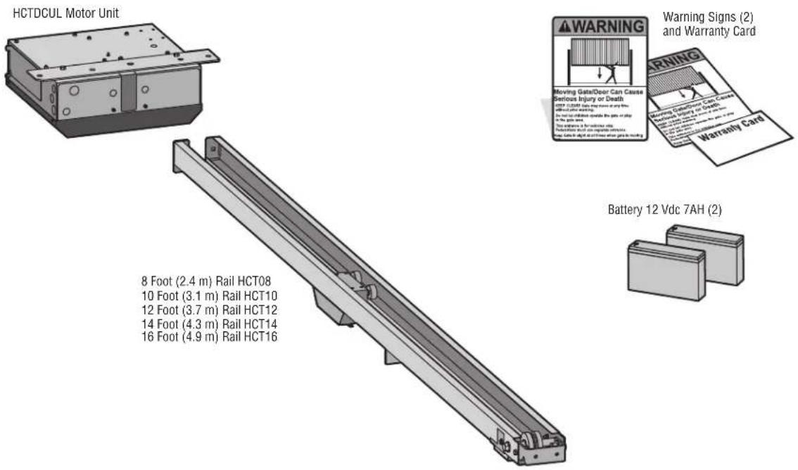
Carton Inventory
NOT SHOWN: Documentation Packet (includes installation manual and antenna)
text_image
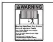
HCTDCUL Motor Unit 8 Foot (2.4 m) Rail HCT08 10 Foot (3.1 m) Rail HCT10 12 Foot (3.7 m) Rail HCT12 14 Foot (4.3 m) Rail HCT14 16 Foot (4.9 m) Rail HCT16 Warning Signs (2) and Warranty Card Warning Moving Gate/Door Can Cause Serious Injury or Death with 120000 miles from the train or ship with 15000 miles from the ship or ship in the car or ship Stop between 1 for additional lift. Stop between 2 and 3 for complete clearance. Stop between 4 and 5 for other lift or lock Battery 12 Vdc 7AH (2)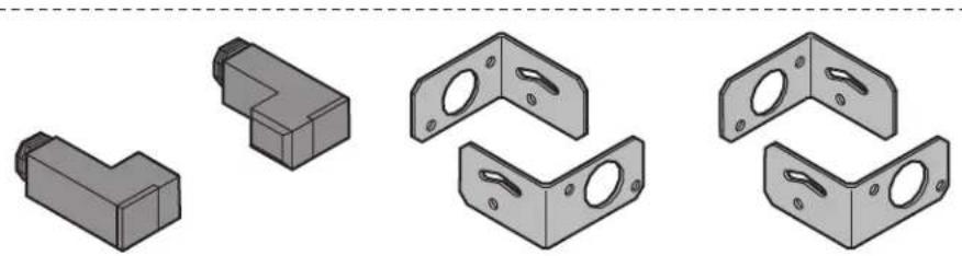
natural_image
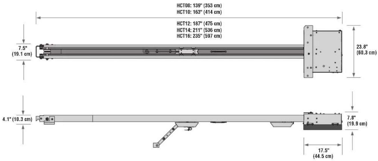
Illustration of various L-shaped metal bracket components (no text or symbols)LiftMaster Photoelectric Sensors (CPSUN4G)
INTRODUCTION
Operator Specifications
| Usage Classification | Class II, III, & IV | |
| Main AC Supply | 120 Vac, 4 Amps OR 240 Vac, 2 Amps | |
| System Operating Voltage | 24 Vdc Transformer Run / Battery Backup | |
| Accessory Power | 24 Vdc, 500mA max. for ON + SW (switched) | |
| Solar Power Max | 24 Vdc at 60 watts max. | |
| Variable Operating Lengths (Operator Weights) | 8 foot (2.4 m) gate - 11.75 foot (3.6 m) operator length (130 lbs. [58.9] | |
| 10 foot (3.1 m) gate - 13.75 foot (4.2 m) operator length (145 lbs. [65.7] | ||
| 12 foot (3.7 m) gate - 15.75 foot (4.8 m) operator length (160 lbs. [72.5] | ||
| 14 foot (4.3 m) gate - 17.75 foot (5.4 m) operator length (175 lbs. [79.4] | ||
| 16 foot (4.9 m) gate - 19.75 foot (6.0 m) operator length (190 lbs. [86.2] | ||
| Maximum Gate/Door Weight | 1000 lbs. (453.6 kg) | |
| Maximum Gate/Door Width (sectional and one-piece) ft. (6.7 m) | ||
| Travel Speed | Default - 8 inches (20.3 cm) per second | |
| Fast - 11 inches (27.9 cm) per second (open speed only) | ||
| Maximum Daily Cycle Rate | HCT08, HCT10 and HCT12 - Continuous | |
| HCT14 and HCT16 - 500 cycles a day | ||
| Maximum Duty Cycle | Continuous | |
| Operating Temperature | -20°C to 60°C (-4°F to 140°F) | |
| Expansion Board | Provided | |
| External Entrapment Protection Device Inputs (non-contact board - up to 2 close entrapment protection devices and 1 open entrance and/or contact) | Expansion board - up to 3 entrapment protection devices configurable to either open and up to 4 edge sensors using wireless edge sensor kit model LMWE | |
text_image
HCT08: 139" (353 cm) HCT10: 163" (414 cm) HCT12: 187" (475 cm) HCT14: 211" (536 cm) HCT16: 235" (597 cm) 7.5" (19.1 cm) 23.8" (60.3 cm) 4.1" (10.3 cm) 7.8" (19.9 cm) 17.5" (44.5 cm)INTRODUCTION
Overview of Typical Installation
Check the national and local building codes BEFORE installation.
NOTE: One or more contact or non-contact external monitored entrapment protection systems shall be located where the risk of entrapment or obstruction exists at either the opening or closing direction. Care shall be exercised to reduce the risk of nuisance tripping, such as when a vehicle trips the sensor while the gate/door is still moving. See page 13 for installation of required entrapment protection devices.
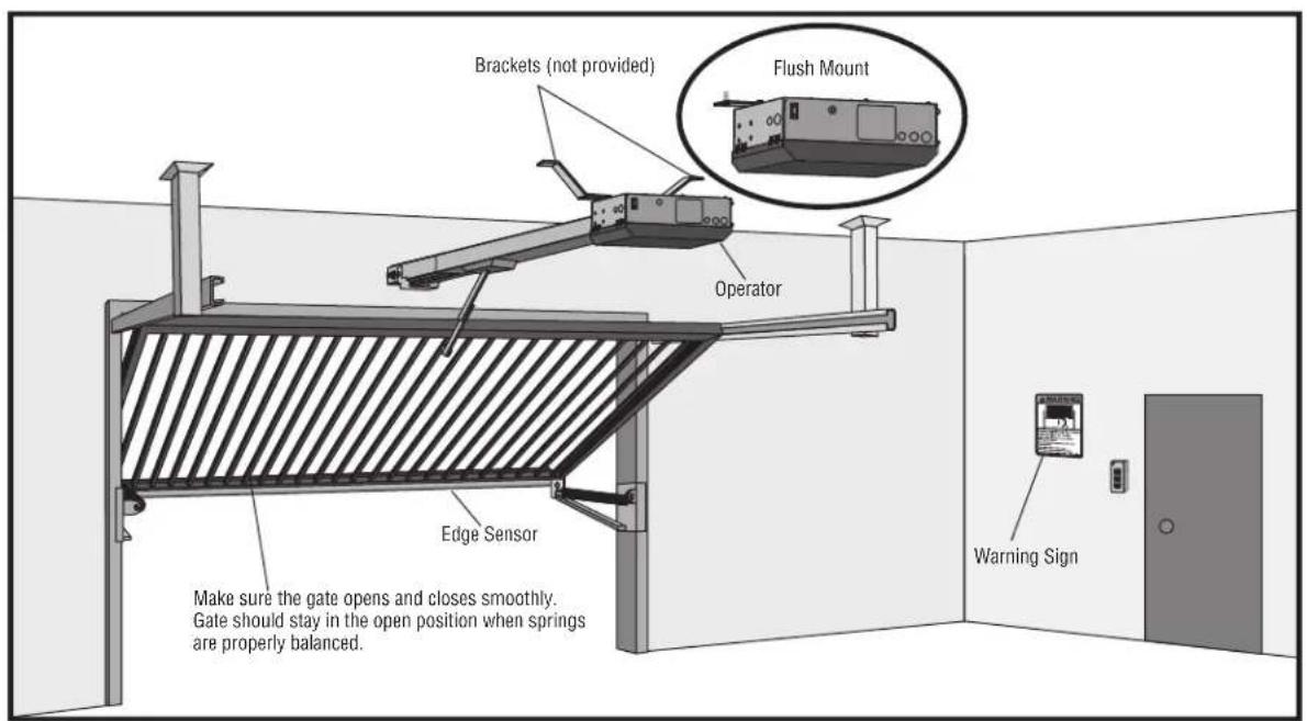
text_image
Brackets (not provided) Flush Mount Operator Edge Sensor Make sure the gate opens and closes smoothly. Gate should stay in the open position when springs are properly balanced. Warning Sign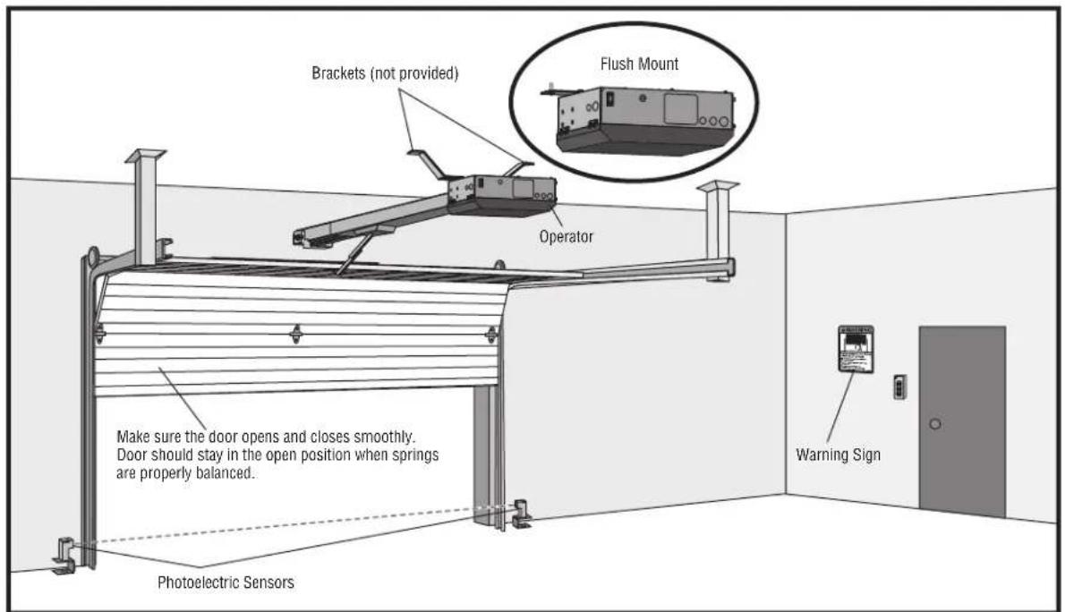
text_image
Brackets (not provided) Flush Mount Operator Make sure the door opens and closes smoothly. Door should stay in the open position when springs are properly balanced. Photoelectric Sensors Warning SignIllustrations are for reference only; your application may look different.
INSTALLATION
IMPORTANT INSTALLATION INSTRUCTIONS
WARNING
TO REDUCE THE RISK OF SEVERE INJURY OR
DEJ
-
READ AND FOLLOW ALL INSTRUCTIONS.
-
Install control station:
-
Install operator ONLY on properly balanced and lubricated door. An improperly balanced gate/door may NOT reverse required and could result in SEVERE INJURY or DEATH.
get within sight of the gate/door without reach of small children at a minimum height of 5 (1.5 m) above floors, landings, steps or any other adjacent
- ALL repairs to cables, spring assemblies and other hardv MUST be made by a trained systems technician BEFORE operator.
are walking surface. installing east 6 feet (1.8 m) from the gate/door or ANY moving the gate/door
- Disable ALL locks and remove ALL ropes connected td1. BEFORE installing operator to avoid entanglement.
gate/door operator is intended for vehicular use ONLY. To prevent INJURY to pedestrians, a separate pedestrian access should be supplied, visible from the gate/door. Locate the pedestrian access where there is NOT a chance of INJURY at ANY point during movement of the gate/door.
- Install gate/door operator 8 feet (2.4 m) or more above
prevent a install Warning signs on EACH side of gate/door in PLAIN VI install one Warning Sign next to the control station. Permanent secure each Warning sign in a suitable manner using fastening
-
NEVER connect operator to power source until instructed
-
Any openings shall be designed, guarded or screened to 4" (10.2 cm) diameter sphere from passing through the anywhere in the gate/door.
SAVE THESE INSTRUCTIONS.
-
Entrapment protection devices MUST be installed to protect who may come near a moving gate/door. Upon completion installation, test entrapment protection device.
-
Too much force on gate/door will interfere with proper operation of safety reversal system.
-
NEVER increase force beyond minimum amount required to move gate/door.
- NEVER use force adjustments to compensate for a binding or sticking gate/door.
- If one control (force or travel limits) is adjusted, the other control may also need adjustment.
CAUTION
- ALWAYS wear protective gloves and eye protection when changing the battery or working around the battery compartment.
- NEVER wear watches, rings or loose clothing while installing or servicing operator. They could be caught in gate/door or operator mechanisms.
INSTALLATION
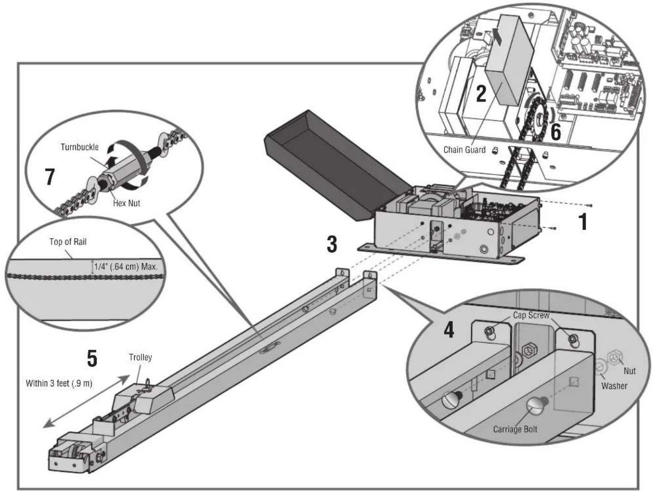
Step 1 Connect Rail to Operator
- Remove the screws and open the cover of the operator.
- Remove the chain guard from the chassis.
- Lay the rail on the floor. Align the key holes on the end of the rail with the cap screws on the chassis.
- Attach the rail to the chassis with the carriage bolts, lock nuts, and washers provided. Tighten cap screws on key holes.
- Cut the cable tie on the chain and position the trolley within 3 feet (.9 m) of the end of the rail.
- Wrap the chain around the sprocket.
- Adjust the chain tension with the turnbuckle so that the chain hangs no more than 1/4" (.64 cm) from the top of the rail. Tighten the hex nut to secure the chain.
- Reattach the chain guard to the chassis.
- Close the cover and attach with screws.
text_image
Turnbuckle Hex Nut Top of Rail 1/4" (.64 cm) Max. 5 Within 3 feet (.9 m) Trolley 3 1 2 6 Chain Guard Cap Screw Nutm Washer Carriage BoltINSTALLATION
Step 2 Install Vented Plug
- Remove the dome plug from the operator chassis.
- Remove the solid plug in the gear reducer and replace vented plug (provided in bag with manual).
- Tighten the vented plug with a socket or Allen wrench.
- Re-insert the dome plug.

text_image
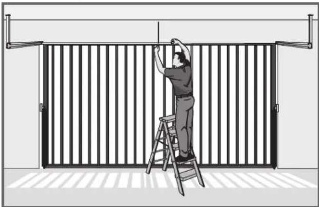
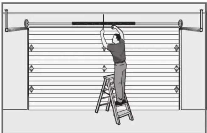
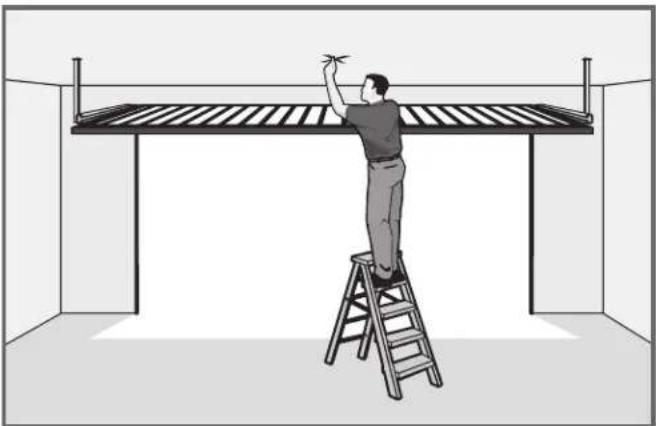
with the Dome Plug Vented PlugStep 3 Determine Location for Operator
- With the gate/door closed, mark the center.
natural_image
Illustration of a person climbing a ladder inside a metal fence (no text or symbols)- Open the gate/door and mark the center point on the
natural_image
Illustration of a person on a ladder installing or adjusting a wall-mounted device (no text or symbols visible)ceiling.
natural_image
Illustration of a person on a ladder installing or adjusting a large metal frame structure (no text or symbols present)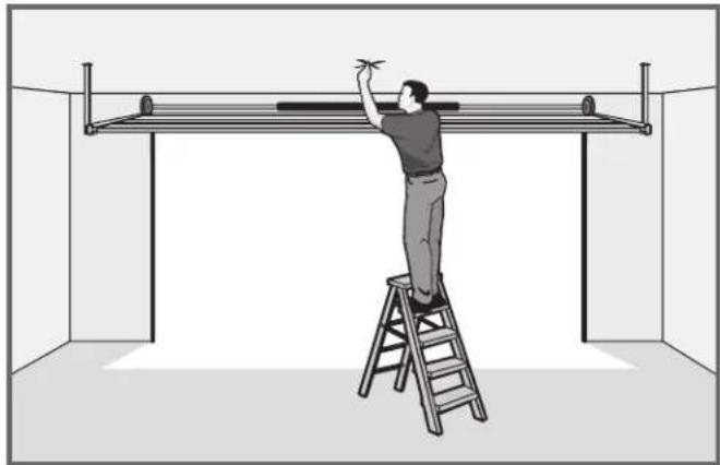
natural_image
Illustration of a person on a ladder installing or adjusting a metal frame inside a room (no text or symbols)INSTALLATION
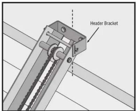
Step 4 Mount the Operator
- Place the motor unit on packing material to protect the cover. Make sure the header bracket is in the center of the opening. Bolt or weld the header bracket to the wall.
text_image
Header Bracket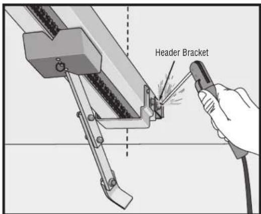
text_image
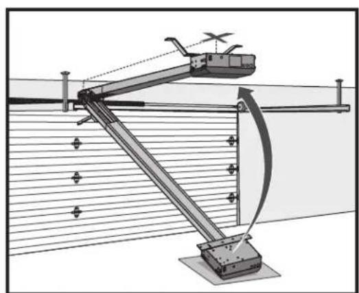
Header Bracket- Lift the operator and align with center mark on ceiling. Have someone hold the operator in place or use a post as a temporary support. Bolt the operator to the ceiling. (A support post is not part of the operator. Use only for installation.) NOTE: The HCT14 and HCT16 rails have an additional mounting hole in the middle of the rail for installing an additional support bracket (not included).
natural_image
Technical diagram of a mechanical linkage system with no visible text or symbols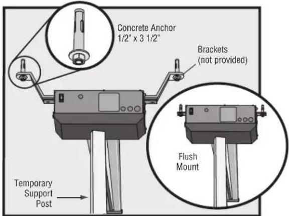
text_image
Concrete Anchor 1/2' x 3 1/2' Brackets (not provided) Flush Mount Temporary Support Post- Bolt or weld arm to gate/door.
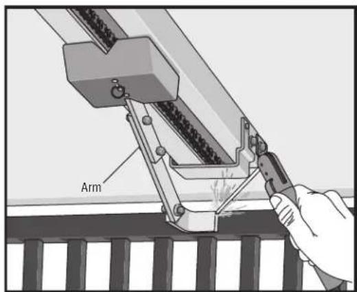
text_image
Arm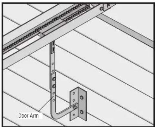
text_image
Door ArmINSTALLATION
WARNING
To prevent SERIOUS INJURY or DEATH from a moving gate/door:
- Entrapment protection devices MUST be installed to protect Laucabene entrapment protection devices to protect between moving who may come near a moving gate/door. gate/door and RIGID objects, such as posts, or walls.
- Locate entrapment protection devices to protect in BOTH the open and close gate/door cycles.
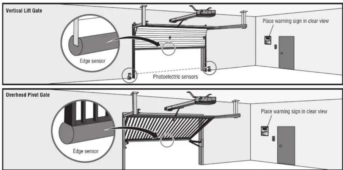
Step 5 Install Entrapment Protection
Entrapment protection MUST be installed according to the following Definitions
325 requirements:
- Vertical gate/door operators require the installation of the external monitored entrapment protection device in the close direction to function.
- Every installation is unique. It is the responsibility of the ensure that ALL entrapment zones are protected with an monitored entrapment protection device, protecting both the and close gate/door cycles.
- LiftMaster monitored external entrapment protection devices be used with LiftMaster operators to meet UL325 require see Accessories.
- Test ALL entrapment protection devices after completing of the operator. For testing instructions, refer to the with your entrapment protection device.
ENTRAPMENT: The condition when a person is caught or held in position that increases the risk of injury.
VERTICAL LIFT GATE ENTRAPMENT ZONE: Locations between a mo gate or exposed operator components and a counter opposing edge. Enster where entrapment is possible up to 2.4 m (8 ft) above externals occur when the gap between a moving gate and fixed opposing edges or surfaces, other than the ground or floor at the gate, is greater than 101.6 mm (4 in) and less than 406
MUST the gap between a moving gate and fixed counter opposing emertices at the bottom of the gate is less than 406 mm (16
OVERHEAD PIVOT GATE ENTRAPMENT ZONE: Locations between a adjoining gate or exposed operator components and a counter oppositously edge provides surface where entrapment is possible up to 2.4 m (8 grade. Such locations occur when the gap, measured in the horiz plane parallel to the roadway (such as a gate support post) and frame when the gate is in either the fully open position or fully position, is greater than 57 mm (2-1/4 in ) and less than 406 or when the gap between a moving gate and fixed counter opp or surfaces at the bottom of the gate is less than 406 mm (
text_image
Vertical Lift Gate Edge sensor Photoelectric sensors Place warning sign in clear view Overhead Pivot Gate Edge sensor Place warning sign in clear viewIllustration is for example only; your site may have additional entrapment zones which MUST be protected.
INSTALLATION
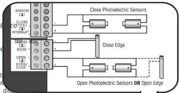
Wire Entrapment Protection Devices
There are three options for wiring the entrapment protection devices depending on the specific device and how the device will function. Refer to the specific entrapment protection device manual for more information. These entrapment protection device inputs are for monitored devices, which include pulsed photoelectric sensors, resistive edge sensors, and pulsed edge sensors. Only one monitored entrapment protection device may be wired to each input. Additional entrapment protection devices may be wired to the expansion board.
Control Board
CLOSES EYES/INTERRUPT
(2 Terminals) The CLOSE EYES/INTERRUPT input is for photoel sensor entrapment protection for the close direction. When an obstruction is sensed during gate closing the gate will open open position and resets the Timer-to-Close. This input will be disregarded during gate opening.
CLOSE EDGE
(2 Terminals) The CLOSE EDGE input is for edge sensor ent protection for the close direction. When an obstruction is sens gate closing the gate will reverse to the full open position, the Timer-to-Close. This input will be disregarded during gate
OPEN EYES/EDGE
(2 Terminals) The OPEN EYES/EDGE input is for photoelectric sensor edge sensor entrapment protection for the open direction. When an obstruction is sensed during gate opening the gate will reverse for seconds then stop. This input will be disregarded during gate close
text_image
SHADOW CLOSE YES / INTERRUPT Close Photoelectric Sensors Close Edge Open Photoelectric Sensors OR Open Edge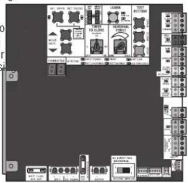
text_image
Circuit board layout with labeled components including switches, relays, and metersExpansion Board
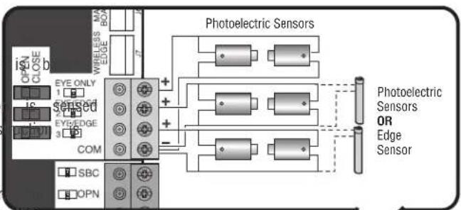
EYE ONLY and COM
Open or Close Direction Photoelectric Sensors, the functionality on the switch settings (located next to the terminals)
Switch set to CLOSE: gate reverses fully when an obstructio
Switch set to OPEN: gate reverses 4 seconds when an obs sensed
EYE/EDGE and COM
Open or Close Direction Photoelectric Sensors or Edge Sensor functionality is based on the switch settings (located next to terminals)
Switch set to CLOSE: gate reverses fully when an obstruction is sens
Switch set to OPEN: gate reverses 4 seconds when an obstruction is sensed
text_image
iSNC OPEN CLOSE EYE ONLY 1 1C sensed 2 EYE/EDGE 3 COM SBC OPN WIRELESS EDGE BOX Photoelectric Sensors + + - Photoelectric Sensors OR Edge Sensor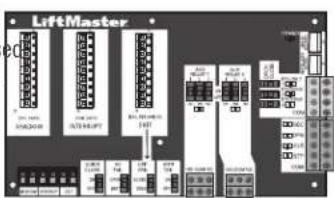
text_image
LiftMaster 100V 300V 100V 300V 100V 300V 100V 300V 100V 300V 100V 300V 100V 300V 100V 300V 100V 300V 100V 300V 100V 300W 100V 300W 100V 300W 100V 300W 100V 300W 100V 300W 100V 300W 100V 300W 100V 300W 100V 300W 100V 300M 100V 300M 100V 300M 100V 300M 100V 300M 100V 300M 100V 300M 100V 300M 100V 300M 100V 300M 100V 300N 100V 300N 100V 300N 100V 300N 100V 300N 100V 300N 100V 300N 100V 300N 100V 300N 100V 300N 100V 300M 100V 300M 100V 300M 100V 300M 100V 300M 100V 300M 100V 300M 155A 155B 155C 155D 155E 155F 155G 155H 155I 155J 155K 155L 155M 155N 155O 155P 155Q 155R 155S 155T 155U 155V 155W 155X 155Y 155Z 155A 155B 155C 155D 155E 155F 155G 155H 155I 155J 155K 155L 155M 155N 155O 155P 155Q 155Z 155A 155AWIRING
WARNING
To reduce the risk of SEVERE INJURY or DEATH:
- ANY maintenance to the operator or in the area near the AL operation electrical connections MUST be made by a qualified individu MUST NOT be performed until disconnecting the electrical power NOT (AC install ANY wiring or attempt to run the operator with or solar and battery) and locking-out the power via the operating power wiring diagram.
switch. Upon completion of maintenance the area MUST be cleared and secured, at that time the unit may be returned to service power wiring should be on a dedicated circuit and well p the location of the power disconnect should be visible and cle - Disconnect power at the fuse box BEFORE proceeding. Operator labeled. MUST be properly grounded and connected in accordance with national and local electrical codes. NOTE: The operator should be on a separate fused line of adequate capacity.
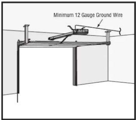
Step 6 Power Wiring
All control wiring used to connect external devices to Class 2 cl operator must be (QPTZ) Power-Limited Circuit Cables, Type CL2, or CL2X or other cable with equivalent or better electrical, mechanical flammability ratings.
NOTE: The operator can also be powered by solar panels, refer extranet on LiftMaster.com for more information.
Proper grounding gives an electrical charge, such as from an elec discharge or a near lightning strike, a path from which to dissip safely into the earth. The ground wire MUST be a single, whole NEVER splice two wires for the ground wire. If you should cut short, break it, or destroy its integrity, replace it with a single proper type earth ground rod for your local area. In certain circle water pipes may be allowed for grounding the operator. Check and codes for proper grounding procedures.
| AMERICAN WIREGAUGE (AWG) | MAXIMUM WIRELENGTH (120 VAC) | MAXIMUM WIRELENGTH (240 VA) | ||||
| rical, and 14 | 130 feet (39.6 m) | 260 feet (79.3 m) | ||||
| to the 12ealer | 205 feet (62.5 m) | 410 feet (125 m) | ||||
| 10 | 325 feet (99.1 m) | 650 feet (198.1 m) | ||||
| trical staticate its energy | 520 feet (158.5 m) | 1,040 feet (317 m) | ||||
| piece of wire. | 825 feet (251.5 m) | 1,650 feet (502.9 m) | ||||
| the ground wire towire length. Use the | 1312 feet (399.9 m) | 2,624 feet (739.8 m) | ||||
- Turn off the AC power from the main power source circuit breaker.
- Run the AC power wires to the operator.
- Loosen the nut on the cover of the EMI board and slide the cover back.
- Connect the green wire to the ground wire using a wire nut.
- Connect the white wire to NEUTRAL using a wire nut.
- Connect the black wire to HOT using a wire nut.
- Ensure the power wiring connector is connected to either the 120 or 240 Vac socket depending on the application. Factory default is 120 Vac.
- Slide the EMI cover back and tighten nut.
- Connect the batteries then turn on the AC power. Connect the J15 plug to the control board.
NOTE: The AC Power switch on the operator will turn the incoming 120/240 Vac power ON or OFF. The operator's AC Power switch ONLY turns off AC power to the control board and DOES NOT turn off battery power.
text_image
Minimum 12 Gauge Ground Wire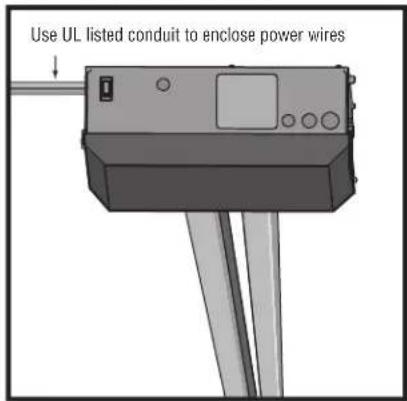
text_image
Use UL listed conduit to enclose power wires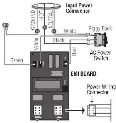
text_image
Input Power Connection GROUND HOT NEUTRAL White Piggy Back White Black Red AC Power Switch Green EMI BOARD Power Wiring Connector 340Vdc 120VdcPower Wiring Sockets (120 Vac factory default)
WIRING
Step 7 Connect Batteries and Attach Antenna
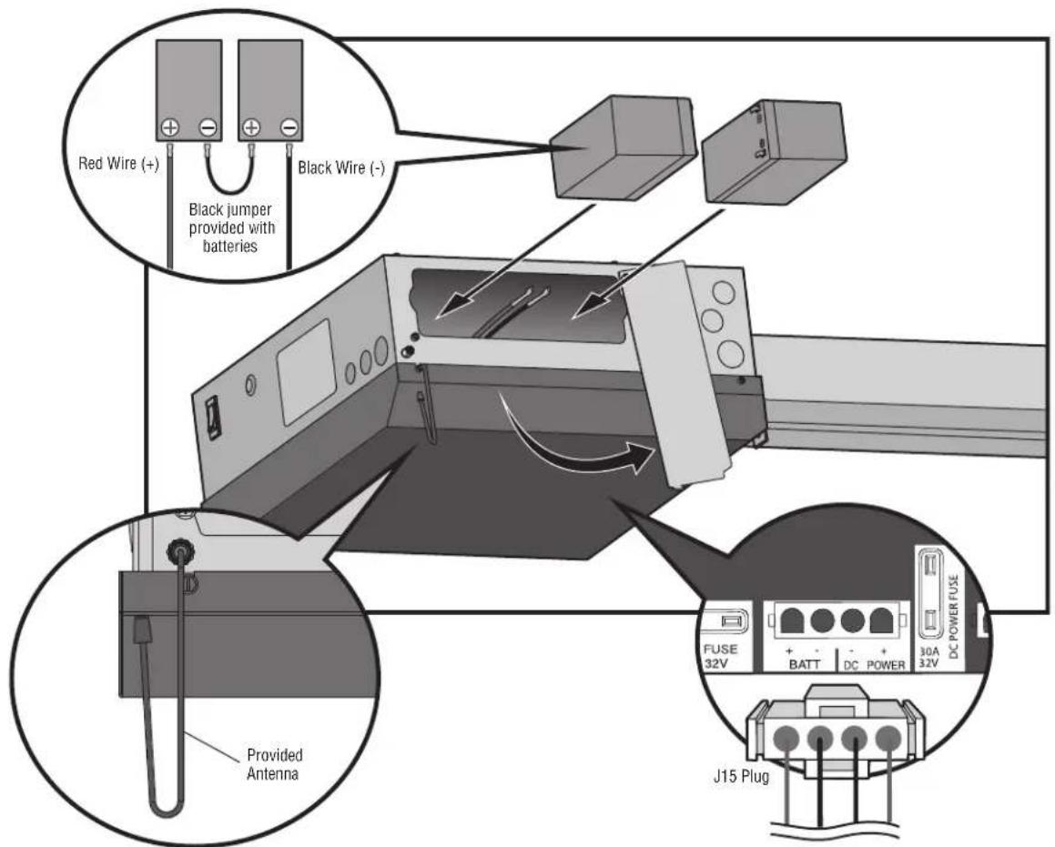
The batteries are charged in the circuit by the integrated transformer. The batteries are for battery backup.
- Unplug the J15 plug labeled BATT on the control board by squeezing the plug and pulling it from the control board. This disconnects the ac/dc power to the control board.
- Loosen the screws on the battery cover and rotate out of the way.
- Connect the red wire to the positive (+) terminal on one battery and connect the black wire to the negative (-) terminal on the other battery.
- Connect the black jumper (included with the batteries) between the positive (+) terminal of one battery to the negative (-) terminal of the other battery.
- Insert the batteries as shown.
- Reattach the battery cover.
- Plug the J15 plug back into the control board. This will power up the control board. NOTE: You may see a small spark when plugging the J15 plug into the board.
- Attach the provided antenna in the orientation shown. ONLY use the provided antenna.
- Turn ON AC power to the operator.
- Turn ON the AC power switch on the operator.
text_image
Red Wire (+) Black jumper provided with batteries Black Wire (-) Provided Antenna FUSE 32V + - BATT DC POWER 30A 32V DC POWER FUSE J15 PlugADJUSTMENT
Limit and Force Adjustment
WARNING
To reduce the risk of SEVERE INJURY or DEATH:
- Without a properly installed safety reversal system, persons NEVER use force adjustments to compensate for a binding or s (particularly small children) could be SERIOUSLY INJURED gate/door.
KILLED by a moving gate or door. If one control (force or travel limits) is adjusted, the other co - Too much force on gate/door will interfere with proper operationalsof need adjustment.
safety reversal system. After ANY adjustments are made, the safety reversal system MU: - NEVER increase force beyond minimum amount required to tested. Gate/door MUST reverse on contact with an object.
gate/door.
Introduction
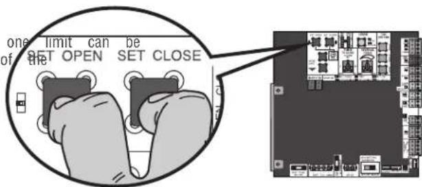
Your operator is designed with electronic controls to make trade and force adjustments easy. The adjustments allow you to provide where the gate/door will stop in the open and close position electronic controls sense the amount of force required to operate the gate/door. The force is adjusted automatically when you limit but should be fine tuned using the REVERSAL FORCE control board (refer to Fine Tune the Force section) to compare environmental changes. The limit setup LEDs (located next to OPEN and SET CLOSE buttons) indicate the status of the line the table to the right.
The limits can be set using the control board (below) or a (refer to Limit Setup with a Remote Control in the Appendix). Setting the limits with a remote control requires a 3-button remote control programmed to OPEN, CLOSE, and STOP.
NOTE: The TEST buttons on the control board will not work until the limits have been set and the required entrapment protection devices are installed.
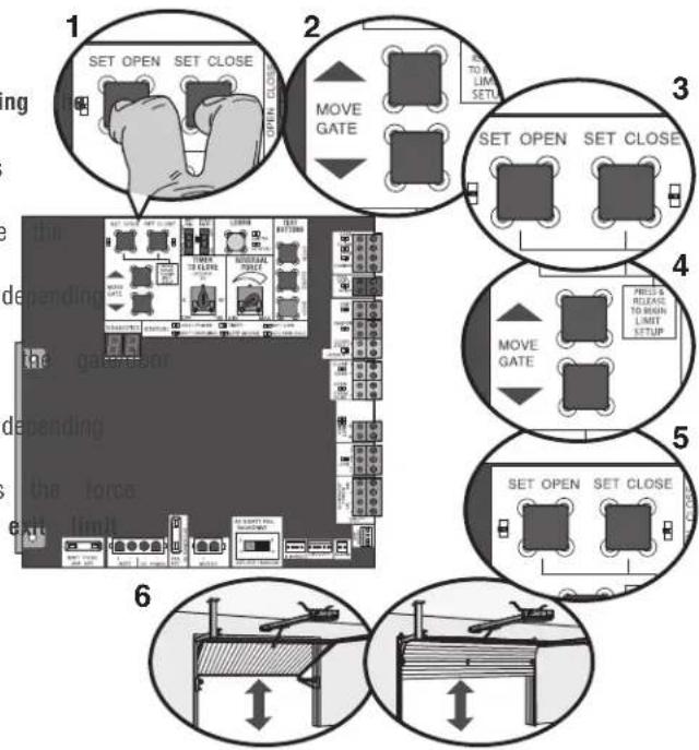
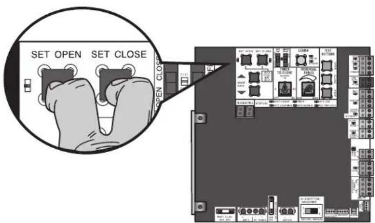
Initial Limits and Force Adjustment
The gate/door MUST be attached to the operator before setting limits and force.
- Press and release the SET OPEN and SET CLOSE buttons simultaneously to enter limit setting mode.
- Press and hold one of the MOVE GATE buttons to move gate/door to the open or close limit.
- Press and release the SET CLOSE or SET OPEN button on which limit is being set.
- Press and hold one of the MOVE GATE button to move to the other limit.
- Press and release the SET CLOSE or SET OPEN button on which limit is being set.
- Cycle the gate/door open and close. This automatically sets When limits are set properly the operator will automatically setting mode.
| LIMIT SETUP LEDS | |||
| level limitprogram.Tlen and close program the | SETCLOSELED | OPERATORMODE | EXPLANATION |
| MODE Limits | are set | ||
| dALINKINGtheensate forthe SEThits, refer | BLINKING | LIMIT SETTINGMODE | Limits are not set |
| ON LIMITto | ON LIMIT | SETTINGMODE | Open limit is not |
| ON BLINKINGLIMIT SETTINGMODE | ON LIMIT | SETTINGMODE | Close limit is not |
| ON ON LIMIT | ON ON | SETTINGMODE | Limits are set |
text_image
1 SET OPEN SET CLOSE 2 MOVE GATE 3 SET OPEN SET CLOSE 4 MOVE GATE 5 SET OPEN SET CLOSE 6ADJUSTMENT
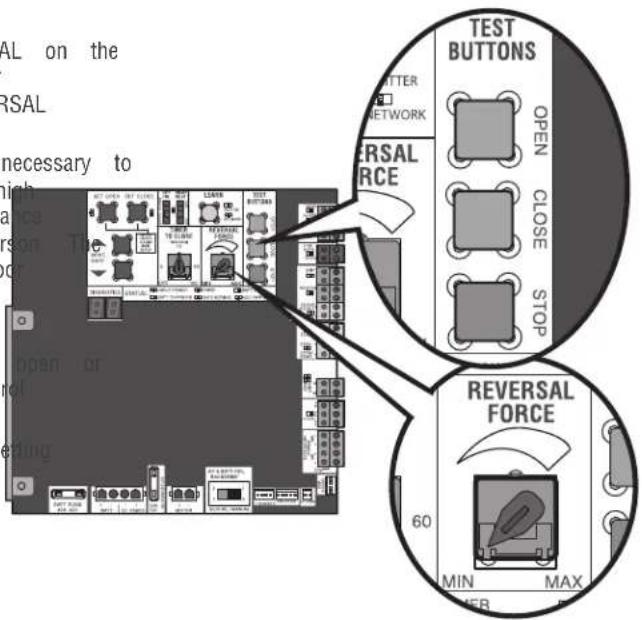
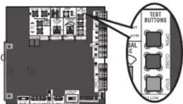
Fine Tune the Force
Once the initial limits have been set, the REVERSAL FORCE DIAL on the control board is used for fine tuning the force where wind or environmental changes may affect the gate/door travel. The REVERSAL FORCE DIAL is set to minimum at the factory.
Based on the length and weight of the gate/door it may be necessary to make additional force adjustments. The force setting should be hi enough that the gate will not reverse by itself nor cause nuisa interruptions, but low enough to prevent serious injury to a pers force setting is the same for both the open and close gate/doc directions.
- Open and close the gate/door with the TEST BUTTONS.
- If the gate/door stops or reverses before reaching the fully closed position, increase the force by turning the force control slightly clockwise.
- Perform the "Obstruction Test" after every limit and force se adjustment (see below).
text_image
SAL on the SAL necessary to high ance person T or reiding TEST BUTTONS TATTER NETWORK SAL RCE OPEN CLOSE STOP REVERSAL FORCE 60 MIN MAX PERAdjust the Limits
After both limits are set and the operator is ready to run, one adjusted independently from the other by following steps 1-3 of Initial Limit and Force Adjustment section.
text_image
one limit can be of the SET OPEN SET CLOSEObstruction Test
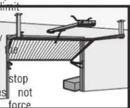
The operator is equipped with an inherent (built in to the operator) obstruction sensing device. If the gate/door encounters an obstruction during motion, the operator will reverse direction of the gate/door and then stop The following procedure will test ONLY the inherent (built the operator) obstruction sensing device:
- Open and close the gate/door with the TEST BUTTONS, ensu that the gate/door is stopping at the proper open and close positions.
- Place an object under the open gate/door. Make sure that a external entrapment protection devices will NOT be activated by object.
- Run the gate/door in the close direction. The gate/door should and reverse upon contact with the object. If the gate/door d reverse off the object, reduce the force setting by turning the control slightly counter-clockwise. The gate/door should have enough force to reach both the open and close limits, but reverse after contact with an object.
- Repeat the test for the open direction.
Test the operator after any adjustments are made.
1
text_image
TEST BUTTONS BALANCE CLOSE STOPF
text_image
limit stop s not forceF

text_image
UST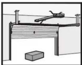
natural_image
Simple line drawing of a mechanical setup with a lever and block, no text or symbols present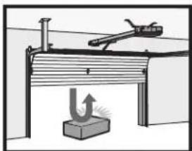
natural_image
Diagram of a mechanical setup with a lever and base, showing no text or symbolsOPERATOR OVERVIEW
text_image
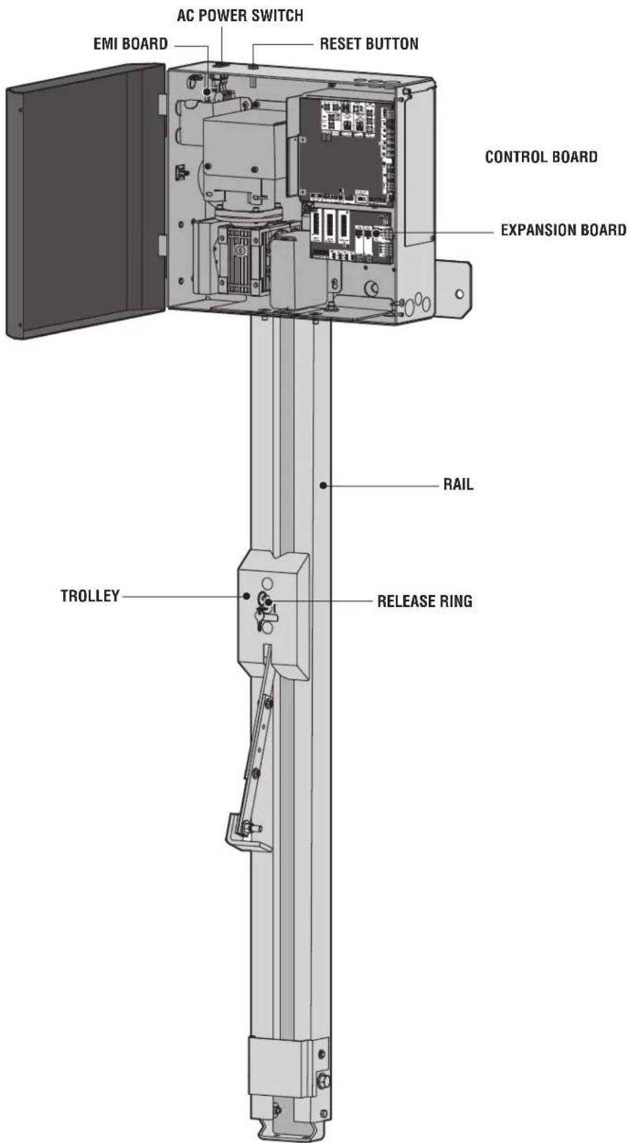
AC POWER SWITCH EMI BOARD RESET BUTTON CONTROL BOARD EXPANSION BOARD RAIL TROLLEY RELEASE RINGPROGRAMMING
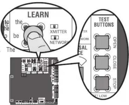
Remote Controls (Not Provided)
A total of 50 Security remote controls or KPW250 keypads and 2 keyless entries (1 PIN for each keyless entry) can be programmed operator. When programming a third keyless entry to the operator, first keyless entry will be erased to allow the third keyless entry programmed. When the operator's memory is full it will exit the programming mode and the remote control will not be programmed. Memory will need to be erased before programming any additional remote controls. NOTE: If installing an 86LM to extend the range of the remote controls DO NOT straighten the antenna.
text_image
LEARN the be The XMITTER NETWORK TEST BUTTONS TETER NETWORK SAL ICE OPEN CLOSE STOP ALT LOWThere are 3 different options for programming the remote control depending on how you would like the remote control to function. Choose a programming option:
| OPTION DESCRIPTION PROGRAMMING STEPS | ||
| Single button as OPEN only | Program a single button on the control for open only. The Timer-to-can be set to close the gate. | remotePress and release the LEARN button (operator will bee-ClosXMITTER LED will light).NOTE: The operator will time programming mode after 30 seconds.2. Press the OPEN button.3. Press the remote control button that you would like to |
| Single button (SBC) as OPEN, CLOSE, and STOR | Program one remote control buttonOpen, close, and stop. | as Press and release the LEARN button (operator will bee XMITTER LED will light).NOTE: The operator will time programming mode after 30 seconds.2. Press the remote control button that you would like to |
| Three separate buttons OPEN, CLOSE, and STOR | aProgram each remote control buttonOpen, close, and stop. | las Press and release the LEARN button (operator will bee XMITTER LED will light).NOTE: The operator will time programming mode after 30 seconds.2. Press the OPEN, CLOSE, or STOP button, depending of function.3. Press the remote control button that you would like to |
The operator will automatically exit learn mode (operator will beep and green XMITTER LED will go out) if programming is successful. To program additional Security+ 2 remote controls or remote control buttons, repeat the programming steps above.
Entering programming mode using external reset button or 3-button control station:
- Make sure gate/door is closed.
- Give the operator an OPEN command.
- Within 30 seconds, when the gate/door is at the open limit press and release the RESET/STOP button twice to put the operator into programming mode. NOTE: The operator will time out of programming mode after 30 seconds.
NOTICE: This device complies with Part 15 of the FCC rules and Industry Canada's license-exempt RSSs. Operation is subject to the following two conditions: (1) this device may not cause harmful interference, and (2) this device must accept any interference received, including interference that may cause undesired operation.
Any changes or modifications not expressly approved by the party responsible for compliance could void the user's authority to operate the equipment. This device must be installed to ensure a minimum 20 cm (8 in.) distance is maintained between users/bystanders and device.
This device has been tested and found to comply with the limits for a Class B digital device, pursuant to part 15 of the FCC rules and Industry Canada ICES standard. These limits are designed to provide reasonable protection against harmful interference in a residential installation. This equipment generates, uses and can radiate radio frequency energy and, if not installed and used in accordance with the instructions, may cause harmful interference to radio communications. However, there is no guarantee that interference will not occur in a particular installation. If this equipment does cause harmful interference to radio or television reception, which can be determined by turning the equipment off and on, the user is encouraged to try to correct the interference by one or more of the following measures:
- Reorient or relocate the receiving antenna.
- Increase the separation between the equipment and receiver.
- Connect the equipment into an outlet on a circuit different from that to which the receiver is connected.
- Consult the dealer or an experienced radio/TV technician for help.
PROGRAMMING
LiftMaster Internet Gateway (not provided)
You will need a broadband internet connection® amultera tdVi-Fi use the LiftMaster Internet Gateway.
To program the operator to the LiftMaster Internet Gateway:
Using the learn button on the opertaor's board
- Connect the ethernet cable to the LiftMaster Internet Gate router.
- Connect power to the LiftMaster Internet Gateway.
- Create an online account by visiting www.myliftmaster.com.
- Register the LiftMaster Internet Gateway.
- Use an internet enabled computer or smartphone to add LiftMaster Internet Gateway will stay in learn mode for
- Press the Learn button twice on the primary operator beep as it enters learn mode). The LiftMaster Internet to the operator if it is within range and the operator programming is successful.
Constant Pressure Override (CPO)
Constant Pressure Override is for use with KPW5 and KPW250 ke (not provided). The KPW5/KPW250 wireless commercial keypads are security keypads and can only be programmed to ONE gate opera the KPW5/KPW250 manual for complete programming instructions).
The Constant Pressure Override feature is intended to temporarily o control the entrapment protection system, in order to operate the the external entrapment protection device is realigned or repaired. L feature only in line of sight of the gate when no obstructions to present. External entrapment protection devices include LiftMaster monitored photoelectric sensors and LiftMaster monitored wired and wireless edge sensors. Be sure to repair or replace these devices, they are not working properly.
To use Constant Pressure Override:
deviEester The valid 4-digit PIN.
three minutes and hold # for 5 seconds to enter CPO. Continue to (the operator the wildperator in motion. A continuous tone will sound un Gateway net with pair # is released.
will the operator will stop when either the operator reaches a lim user releases #.
Using the reset button or 3-button control station
- Connect the ethernet cable to the LiftMaster Internet Gate router.
- Connect power to the LiftMaster Internet Gateway.
- Create an online account by visiting www.myliftmaster.com.
- Register the LiftMaster Internet Gateway.
- Use an internet enabled computer or smartphone to add LiftMaster Internet Gateway will stay in learn mode for
- Ensure gate/door is closed.
- Give the operator an OPEN command.
- Within 30 seconds, when the gate/door is at the open release the reset button 3 times (on primary gate) to operator into High Band Learn Mode (the operator will learn mode). The LiftMaster Internet Gateway will pair to it is within range and the operator will beep if progra successful.
The status as shown by the LiftMaster Internet Gateway app "open" or "closed". The gate/door operator can then be cor the LiftMaster Internet Gateway app.
Erase All Codes
- Press and release the LEARN button (operator will beep XMITTER LED will light).
- Press and hold the LEARN button again until the green flashes and then release the button (approximately 6 sec remote control codes are now erased.
Gate Hold Open Feature
The gate hold open feature will disable the timer and keep the open limit. The gate hold open feature can be activated through Button as described on page 25 or through the KPW5 and KPW:keypads (not provided).
To use the gate hold open feature:
three Eminutes. valid 4-digit PIN when the gate is at the Open Lim timer is running
- The Operator will chirp indicating the timer is canceled.
Limit restarts thed gate:
ut. Remain the 4-digit PIN weep as it enters Activate a hard input or a programmed remote the operator if
To Remove and Erase Monitored will be either Entrapment Protection Devices
- Remove the entrapment protection device wires from the terminal block.
- Press and release the SET OPEN and SET CLOSE buttons simultaneously. The SET OPEN and SET CLOSE LEDs will turn and (enabling learn limit mode).
- Press and release both SET OPEN and SET CLOSE buttons and XMITTER of LED the SET OPEN and SET CLOSE LEDs (exiting learn I
Erase Limits
-
To erase the limits, press and hold the SET OPEN and SET CLOSE buttons simultaneously (5 seconds) until both the SET OPEN and SET CLOSE LEDs blink rapidly and the operator beeps.
-
Release the buttons and the SET OPEN and SET CLOSE LEDs will blink slowly indicating the limits will need to be set.
PROGRAMMING
Limit Setup with a Remote Control
To set the limits using a remote control, first you will need a 3-button remote control that has been programmed for OPEN, CLOSE, and STOP. Refer to the Programming section.
Initial Limits and Force Adjustment
The gate/door MUST be attached to the operator before limits and force.
Ensure the gate/door is closed.
- Press and release the SET OPEN and SET CLOSE button3 simultaneously to enter limit setting mode.
- Press and hold the OPEN or CLOSE button on the until the gate/door reaches the desired open position. can be jogged back and forth using the OPEN and the remote control.
- Once the gate/door is in the desired open position, the STOP button on the remote control.
- Press and release the OPEN button on the remote set the open limit.
- Press and hold the CLOSE or OPEN button on the until the gate/door reaches the desired close position. can be jogged back and forth using the OPEN and the remote control.
- Once the gate/door is in the desired close position, the STOP button on the remote control.
- Press and release the CLOSE button on the remote control set the close limit.
- Cycle the gate/door open and close. This automatically sets When limits are set properly the operator will automatically exit setting mode.
Refer to the Adjustment section and follow the instructions for Fine Tune the Force and Obstruction Test. Perform the "Obstruction Test" after every limit and force setting adjustment.
Adjust the limits
setting the limits have already been set the operator will exit the lim mode after resetting each limit.
Set the Close Limit Only
buttons. Press and release the SET OPEN and SET CLOSE buttons simultaneously to enter limit setting mode.
remote Pressroland hold the CLOSE button on the remote control until The gate/door reaches the desired close position. The gate/door can CLOSE jodgtons back and forth using the OPEN and CLOSE buttons on remote control.
press. a) once release gate/door is in the desired close position, press and the STOP button on the remote control.
control. agains and release the CLOSE button on the remote control ac the close limit.
remWhen control close limit is set properly the operator will automatically These gate/donode.
CLOSE buttons on Limit Only Set the Open
- Press and release the SET OPEN and SET CLOSE buttons press and release simultaneously to enter limit setting mode.
- Press and hold the OPEN button on the remote control until control again to reaches the desired open position. The gate/door can jogged back and forth using the OPEN and CLOSE buttons on sets the remote control.
at once the gate/door is in the desired open position, press and the STOP button on the remote control.
4. Press and release the OPEN button on the remote control against the open limit.
When the open limit is set properly the operator will automatically setting mode.
text_image
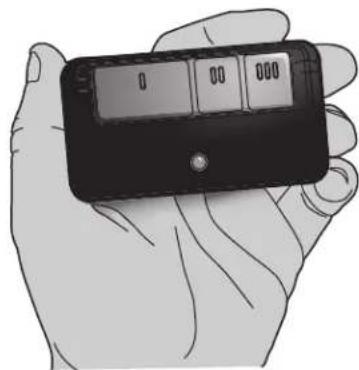
SET OPEN SET CLOSE OPEN CLOSE3-Button Remote Control programmed for OPEN, CLOSE, and STOP
natural_image
Illustration of a hand holding a handheld electronic device with a display screen (no visible text or symbols)OPERATION
Gate/Door Operator Setup Examples
The following are example setups for the gate/door operator. Your specific site requirements may be different. Always setup the operator system to the site requirements, including all necessary entrapment protection devices.
COMMERCIAL/GENERAL ACCESS: A residential community (more than four homes) having one or more gated entrances/exits, allowing vehicle access trumps security concerns
COMMERCIAL: Business site where security (gate/door closed) is important
INDUSTRIAL: Large business site where security is required
| SETTING | COMMERCIAL/GENERAL ACCESS | COMMERCIAL INDUSTRIAL | |
| Quick Close switch setting | Normally set to OFF. Normalgate/c close (timer or control). | Normally set to OFF. Normalgate/c close (timer or control). | Set to ON, so that gate/door cl immediately after vehicle passes O EYES/Interrupt loop. |
| AC Fail Open switch setting | Normally set to BATT. For local requirement, set to OPEN so that gate/door will open approximately seconds after AC power fail. | Not directly onset to BATT. Runonbatter power fails. 15 | Normally AC set to BATT. Runonbatter power fails. |
| Low Battery switch setting | Normally set to OPEN. If power battery and battery is low, gate/door automatically opens andstays open. | Normally set to CLOSE. If power battery and battery is low, gate/door closed. | Normally set to CLOSE. If power batteries and battery is low, gate/door closed. |
| Anti-Tail switch setting | Normally set to OFF. CLOSE EYES/Interrupt loopreverses a closing gate/door. | Set to ON. In attempt to prevent gail-gating, CLOSEEYES/ Interrupt loopgating, CLOSEEYES/ Interrupt loop pauses a closinggate/door. | Set to ON. In attempt to prevent gail-gating, CLOSEEYES/ Interrupt loop pauses a closinggate/door. |
| Bipart Delay switch setting | Normally set to OFF. Normal speed. | Set to ON for high speed help flow in high traffic area | Set to ON for high speed help flow in high traffic area |
| Aux Relay Out - Open Limit Switch withSAMS (Sequence Access Management System). | 1. Use withSAMS (Sequence Access Management System).2. Connect "Gate Open" indicator light). | 1. Use withSAMS (Sequence Access Management System).2. e.gConnect "Gate Open" indicator light). | |
| Aux Relay Out - Close Limit Switchally not required. Connect "Gate Close/Secure" indicator (e.g. light). | Connect "Gate Close/Secure" indicator (e.g. light). | ||
| Aux Relay Out - Gate/door Motion Attach alert signal (audible or vis system). | Attach alert signal (audible or vis system). | Attach alert signal (audible or vis system). | |
| Aux Relay Out - Pre-Motion Del Attach alert signal (audible or vis system). | Attach alert signal (audible or vis system). | Attach alert signal (audible or vis system). | |
| Aux Relay Out - Power Attach visual alert to know when is chargingbatteries (i.e. not running batteries). | Attach visual alert to know when is on chargingbatteries (i.e. not running batteries). | Attach visual alert to know when is on chargingbatteries (i.e. not running batteries). | |
| Aux Relay Out - Tamper Attach alert signal (audible or vis system) to indicate if gate/door manually tampered withby beingpushed annually tampered withby beingpushed annually tampered withby beingpushed annually tampered withby beingpushed annually tampered withby beingpushed annually tampered withby beingpushed annually tampered withby beingpushed annually tampered withby beingpushed annually tampered withby beingpushed annually tampered withby beingpushed annually tampered withby beingpushed annually tampered withby beingpushed annually tampered withby beingpushed annually tampered with by beingpushed annually tampered with by beingpushed annually tampered with by beingpushed annually tampered with by beingpushed annually tampered with by beingpushed annually tampered with by beingpushed annually tampered with by beingpushed annually tampered with by beingpushed annually tampered with by beingpushed annually tampered with by beingpushed annually tampered with by beingpushed annually tampered with by beingpushed annually tampered with by beingpushed annual tampered with by beingpushed annually tampered with by beingpushed annually tampered with by beingpushed annually tampered with by beingpushed annually tampered with by beingpushed annually tampered with by beingpushed annually tampered with by beingpushed annually tampered with by beingpushed annually tampered with by beingpushed annually tampered with by beingpushed annually tampered with by beingpushed annually tampered with by beingpushed annually tampered with By beingpushed annually tampered with by beingpushed annually tampered with by beingpushed annually tampered with by beingpushed annually tampered with by beingpushed annually tampered with by beingpushed annually tampered with by beingpushed annually tampered with by beingpushed annually tampered with by beingpushed annually tampered with by beingpushed annually tampered with by beingpushed annually tampered with by beingpushed annually tampered with by beingpushed approximately tampered with by beingpushed annually tampered with by beingpushed annually tampered with by beingpushed annually tampered with by beingpushed annually tampered with by beingpushed annually tampered with by beingpushed annually tampered with by beingpushed annually tampered with by beingpushed annually tampered with by beingpushed annually tampered with by beingpushed annually tampered with by beingpushed annually tampered with by beingpushed annually tampered withby beingpushed annually tampered with by beingpushed annually tampered with by beingpushed annually tampered with by beingpushed annually tampered with by beingpushed annually tampered with by beingpushed annually tampered with by beingpushed annually tampered with by beingpushed annually tampered with by beingpushed annually tampered with by beingpushed annually tampered with by beingpushed annually tampered with by beingpushed annual tampered with by beingpushed annual tampered with by beingpushed annually tampered with by beingpushed annually tampered with by beingpushed annually tampered with by beingpushed annually tampered with by beingpushed annually tampered with by beingpushed annually tampered with by beingpushed annually tampered with by beingpushed annually tampered with by beingpushed annually tampered with by beingpushed annually tampered with by beingpushed annually tampered withby beingpushed annually tampered withby beingpushed annually tampered withby beingpushed annually tampered withby beingpushed annually tampered withby beingpushed annually tampered withby beingpushed annually tampered withby beingpushed annually tampered withby beingpushed annually tampered withby beingpushed annually tampered withby beingpushed annually tampered withby beingpushed annually tampered withby beingpushed annual tampered withby beingpushed annually tampered withby beingpushed annually tampered withby beingpushed annually tampered withby beingpushed annually tampered withby beingpushed annually tampered withby beingpushed annually tampered withby beingpushed annually tampered withby beingpushed annually tampered withby beingpushed annually tampered withby beingpushed annually tampered withby beingpushed annually tampered withby beingpushed annually tampered withBy beingpushed annually tampered withby beingpushed annually tampered withby beingpushed annually tampered withby beingpushed annually tampered withby beingpushed annually tampered withby beingpushed annually tampered withby beingpushed annually tampered withby beingpushed annually tampered withby beingpushed annually tampered withby beingpushed annually tampered withby beingpushed annually tampered withby beingpushed annually tampered withby beingpushed approximately tampered with by beingpushed annually tampered with by beingpushed annually tampered with by beingpushed annually tampered with by beingpushed annually tampered with by beingpushed annually tampered with by beingpushed annually tampered with by beingpushed annually tampered with by beingpushed annually tampered with by beingpushed annually tampered with by beingpushed annually tampered with by beingpushed annually tampered with by beingpushed annual tampered withby beingpushed annually tampered withby beingpushed annually tampered withby beingpushed annually tampered withby beingpushed annually tampered withby beingpushed annually tampered withby beingpushed annually tampered withby beingpushed annually tampered withby beingpushed annually tampered withby beingpushed annually tampered withby beingpushed annually tampered withby beingpushed annually tampered withby beingpushed annual tampered with by beingpushed annually tampered with by beingpushed annually tampered with by beingpushed annually tampered with by beingpushed annually tampered with by beingpushed annually tampered with by beingpushed annually tampered with by beingpushed annually tampered with by beingpushed annually tampered with by beingpushed annually tampered with by beingpushed annually tampered with by beingpushed annually tampered with by beingpushed annual tampered with By beingpushed annually tampered with by beingpushed annually tampered with by beingpushed annually tampered with by beingpushed annually tampered with by beingpushed annually tampered with by beingpushed annually tampered with by beingpushed annually tampered with by beingpushed annually tampered with by beingpushed annually tampered with by beingpushed annually tampered with by beingpushed annually tampered with by beingpushed annually tampered with By beingpushed annual tampered with by beingpushed annually tampered with by beingpushed annually tampered with by beingpushed annually tampered with by beingpushed annually tampered with by beingpushed annually tampered with by beingpushed annually tampered with by beingpushed annually tampered with by beingpushed annually tampered with by beingpushed annually tampered with by beingpushed annually tampered with by beingpushed annually tampered with by beingpushed approximately tampered with By beingpushed annually tampered with by beingpushed annually tampered with by beingpushed annually tampered with by beingpushed annually tampered with by beingpushed annually tampered with by beingpushed annually tampered with by beingpushed annually tampered with by beingpushed annually tampered with by beingpushed annually tampered with by beingpushed annually tampered with by beingpushed annually tampered with by beingpushed annually tampered withby beingpushed annual tampered with by beingpushed annually tampered with by beingpushed annually tampered with by beingpushed annually tampered with by beingpushed annually tampered with by beingpushed annually tampered with by beingpushed annually tampered with by beingpushed annually tampered with by beingpushed annually tampered with by beingpushed annually tampered with by beingpushed annually tampered with by beingpushed annual tampered with by beingpushed annually tampered withby beingpushed annually tampered with by beingpushed annually tampered with by beingpushed annually tampered with by beingpushed annually tampered with by beingpushed annually tampered with by beingpushed annually tampered with by beingpushed annually tampered with by beingpushed annually tampered with by beingpushed annually tampered with by beingpushed annually tampered with by beingpushed annually tampered withby beingpushed annually tampered with by beingpushed annual tampered with by beingpushed annually tampered with by beingpushed annually tampered with by beingpushed annually tampered with by beingpushed annually tampered with by beingpushed annually tampered with by beingpushed annually tampered with by beingpushed annually tampered with by beingpushed annually tampered with by beingpushed annually tampered with by beingpushed annually tampered with by beingpushed annual tampered with by beingpushed annual tampered withby beingpushed annually tampered with by beingpushed annually tampered with by beingpushed annually tampered with by beingpushed annually tampered with by beingpushed annually tampered with by beingpushed annually tampered with by beingpushed annually tampered with by beingpushed annually tampered with by beingpushed annually tampered with by beingpushed annually tampered with by beingpushed annually tampered with by beingpushed annually tampered withby beingpushed approximately tampered with by beingpushed annually tampered with by beingpushed annually tampered with by beingpushed annually tampered with by beingpushed annually tampered with by beingpushed annually tampered with by beingpushed annually tampered with by beingpushed annually tampered with by beingpushed annually tampered with by beingpushed annually tampered with by beingpushed annually tampered with by beingpushed annual tampered with by beingpushed annually tampered with By beingpushed annually tampered with by beingpushed annually tampered with by beingpushed annually tampered with by beingpushed annually tampered with by beingpushed annually tampered with by beingpushed annually tampered with by beingpushed annually tampered with by beingpushed annually tampered with by beingpushed annually tampered with by beingpushed annually tampered with by beingpushed annually tampered withby beingpushed annually tampered with by beingpushed近年 tampered with by beingpushed近年 tampered with by beingpushed近年 tampered with by beingpushed近年 tampered with by beingpushed近年 tampered with by beingpushed近年 tampered with by beingpushed近年 tampered with by beingpushed近年 tampered with by beingpushed近年 tampered with by beingpushed近年 tampered with by beingpushed近年 tampered with by beingpushed近年 tampered with by beingpushed近年 tampered withby beingpushed近年 tampered with by beingpushed近年 tampered with by beingpushed近年 tampered with by beingpushed近年 tampered with by beingpushed近年 tampered with by beingpushed近年 tampered with by beingpushed近年 tampered with by beingpushed近年 tampered with by beingpushed近年 tampered with by beingpushed近年 tampered with by beingpushed近年 tampered with by beingpushed近年 tampered with by beingpushed years tampered with by beingpushed years tampered with by beingpushed years tampered with by beingpushed years tampered with by beingpushed years tampered with by beingpushed years tampered with by beingpushed years tampered with by beingpushed years tampered with by beingpushed years tampered with by beingpushed years tampered with by beingpushed years tampered with by beingpushed years tampered with by beingpushed years tampered withby beingpushed近年 tampered with by beingpushed近年 tampered with by beingpushed近年 tampered with by beingpushed近年 tampered with by beingpushed近年 tampered with by beingpushed近年 tampered with by beingpushed近年 tampered with by beingpushed近年 tampered with by beingpushed近年 tampered with by beingpushed近年 tampered with by beingpushed近年 tampered with by beingpushed近年 tampered withby beingpushed years tampered with by beingpushed years tampered with by beingpushed years tampered with by beingpushed years tampered with by beingpushed years tampered with by beingpushed years tampered with by beingpushed years tampered with by beingpushed years tampered with by beingpushed years tampered with by beingpushed years tampered with by beingpushed years tampered with by beingpushed years tampered with by beingpushedyears tampered with by beingpushed years tampered with by beingpushed years tampered with by beingpushed years tampered with by beingpushed years tampered with by beingpushed years tampered with by beingpushed years tampered with by beingpushed years tampered with by beingpushed years tampered with by beingpushed years tampered with by beingpushed years tampered with by beingpushed years tampered with by beingpushed years tampered with By beingpushed years tampered with by beingpushed years tampered with by beingpushed years tampered with by beingpushed years tampered with by beingpushed years tampered with by beingpushed years tampered with by beingpushed years tampered with by beingpushed years tampered with by beingpushed years tampered with by beingpushed years tampered with by beingpushed years tampered with by beingpushed years tampered with by beingpushedYears tampered with by beingpushedYears tampered with by beingpushedYears tampered with by beingpushedYears tampered with by beingpushedYears tampered with by beingpushedYears tampered with by beingpushedYears tampered with by beingpushedYears tampered with by beingpushedYears tampered with by beingpushedYears tampered with by beingpushedYears tampered with by beingpushedYears tampered with by beingpushedYears tampered with By beingpushedYears tampered with By beingpushedYears tampered with By beingpushedYears tampered with By beingpushedYears tampered with By beingpushedYears tampered with By beingpushedYears tampered with By beingpushedYears tampered with By beingpushedYears tampered with By beingpushedYears tampered with By beingpushedYears tampered with By beingpushedYears tampered with By beingpushedYears tampered with By beingpushedYear tampered with By beingpushedYear tampered with By beingpushedYear tampered with By beingpushedYear tampered with By beingpushedYear tampered with By beingpushedYear tampered with By beingpushedYear tampered with By beingpushedYear tampered with By beingpushedYear tampered with By beingpushedYear tampered with By beingpushedYear tampered with By beingpushedYear tampered with By beingpushedYear tampered withBy beingpushedYears tampered with By beingpushedYears tampered with By beingpushedYears tampered with By beingpushedYears tampered with By beingpushedYears tampered with By beingpushedYears tampered with By beingpushedYears tampered with By beingpushedYears tampered with By beingpushedYears tampered with By beingpushedYears tampered with By beingpushedYears tampered with By beingpushedYears tampered with By beingpushedYE tormam | Connect to ON,If power battery and battery is low,gate/door will open,gate/door open,gate/door open,gate/door open,gate/door open,gate/door open,gate/door open,gate/door open,gate/door open,gate/door open,gate/door open,gate/door open,gate/door open,gate/door open,gate/door open,gate/door open,gate/door open,gate/door open,gate/door open,gate/door open,gate/door open,gate/for,etc,etc,etc,etc,etc,etc,etc,etc,etc,etc,etc,etc,etc,etc,etc,etc,etc,etc,etc,etc,etc,etc,etc,etc,etc,etc,etc,etc,etc,etc,etc,etc,etc,etc,etc,etc,etc,etc,etc,etc,etc,etc,etc,etc,etc,etc,etc,etc,etc,etc, etc,etc,etc,etc,etc,etc,etc,etc,etc,etc,etc,etc,etc,etc,etc,etc,etc,etc,etc,etc,etc,etc,etc,etc,etc,etc,etc,etc,etc,etc,etc,etc,etc,etc,etc,etc,etc,etc,etc,etc,etc,etc,etc,etc,etc,etc,etc,etc,etc,etc,tc,etc,etc,etc,etc,etc,etc,etc,etc,etc,etc,etc,etc,etc,etc,etc,etc,etc,etc,etc,etc,etc,etc,etc,etc,etc,etc,etc,etc,etc,etc,etc,etc,etc,etc,etc,etc,etc,etc,etc,etc,etc,etc,etc,etc,etc,etc,etc,etc,etc,orc,etc,etc,etc,etc,etc,etc,etc,etc,etc,etc,etc,etc,etc,etc,etc,etc,etc,etc,etc,etc,etc,etc,etc,etc,etc,etc,etc,etc,etc,etc,etc,etc,etc,etc,etc,etc,etc,etc,etc,etc,etc,etc,etc,etc,etc,etc,etc,etc,etc,ct,etc,etc,etc,etc,etc,etc,etc,etc,etc,etc,etc,etc,etc,etc,etc,etc,etc,etc,etc,etc,etc,etc,etc,etc,etc,etc,etc,etc,etc,etc,etc,etc,etc,etc,etc,etc,etc,etc,etc,etc,etc,etc,etc,etc,etc,etc,etc,etc,etc,tl,etc,etc,etc,etc,etc,etc,etc,etc,etc,etc,etc,etc,etc,etc,etc,etc,etc,etc,etc,etc,etc,etc,etc,etc,etc,etc,etc,etc,etc,etc,etc,etc,etc,etc,etc,etc,etc,etc,etc,etc,etc,etc,etc,etc,etc,etc,etc,etc,etc,mc,etc,etc,etc,etc,etc,etc,etc,etc,etc,etc,etc,etc,etc,etc,etc,etc,etc,etc,etc,etc,etc,etc,etc,etc,etc,etc,etc,etc,etc,etc,etc,etc,etc,etc,etc,etc,etc,etc,etc,etc,etc,etc,etc,etc,etc,etc,etc,etc,etc,fat,etc,etc,etc,etc,etc,etc,etc,etc,etc,etc,etc,etc,etc,etc,etc,etc,etc,etc,etc,etc,etc,etc,etc,etc,etc,etc,etc,etc,etc,etc,etc,etc,etc,etc,etc,etc,etc,etc,etc,etc,etc,etc,etc,etc,etc,etc,etc,etc,etc,Inc,etc,etc,etc,etc,etc,etc,etc,etc,etc,etc,etc,etc,etc,etc,etc,etc,etc,etc,etc,etc,etc,etc,etc,etc,etc,etc,etc,etc,etc,etc,etc,etc,etc,etc,etc,etc,etc,etc,etc,etc,etc,etc,etc,etc,etc,etc,etc,etc,etc, Inc,etc,etc,etc,etc,etc,etc,etc,etc,etc,etc,etc,etc,etc,etc,etc,etc,etc,etc,etc,etc,etc,etc,etc,etc,etc,etc,etc,etc,etc,etc,etc,etc,etc,etc,etc,etc,etc,etc,etc,etc,etc,etc,etc,etc,etc,etc,etc,etc,etc,vt,etc,etc,etc,etc,etc,etc,etc,etc,etc,etc,etc,etc,etc,etc,etc,etc,etc,etc,etc,etc,etc,etc,etc,etc,etc,etc,etc,etc,etc,etc,etc,etc,etc,etc,etc,etc,etc,etc,etc,etc,etc,etc,etc,etc,etc,etc,etc,etc,etc,ftc,etc,etc,etc,etc,etc,etc,etc,etc,etc,etc,etc,etc,etc,etc,etc,etc,etc,etc,etc,etc,etc,etc,etc,etc,etc,etc,etc,etc,etc,etc,etc,etc,etc,etc,etc,etc,etc,etc,etc,etc,etc,etc,etc,etc,etc,etc,etc,etc,etc,fc,etc,etc,etc,etc,etc,etc,etc,etc,etc,etc,etc,etc,etc,etc,etc,etc,etc,etc,etc,etc,etc,etc,etc,etc,etc,etc,etc,etc,etc,etc,etc,etc,etc,etc,etc,etc,etc,etc,etc,etc,etc,etc,etc,etc,etc,etc,etc,etc,etc,forc,etc,etc,etc,etc,etc,etc,etc,etc,etc,etc,etc,etc,etc,etc,etc,etc,etc,etc,etc,etc,etc,etc,etc,etc,etc,etc,etc,etc,etc,etc,etc,etc,etc,etc,etc,etc,etc,etc,etc,etc,etc,etc,etc,etc,etc,etc,etc,etc,etc,wtc | Connect to ON,If power battery and battery is low,gail-gating,Close/SAMS (Sequence Access Management System). | Connect to ON,If power battery and battery is low,gail-gating,Close/SAMS (Sequence Access Management System). |
OPERATION
Control Board Overview
1 SET OPEN Button: The SET OPEN button sets the OPEN limit. See Adjust Limits section.
2 SET CLOSE Button: The SET CLOSE button sets the CLOSE limit. See Adjust Limits section.
3 MOVE GATE Buttons: The MOVE GATE buttons will either open or close the gate/door when the operator is in Limit setting mode. See Adjust Limits section.
4 BATT FAIL:
- When AC power is OFF and battery voltage is critically low the gate/door will latch at a limit until AC power is restored or batteries voltage increases.
- Option select switch set to OPEN forces gate/door to automatically open and then latch at the OPEN limit until AC power is restored or battery voltage increases.
- Option select switch set to CLOSE forces gate/door to latch at CLOSE limit if at CLOSE limit or on next CLOSE command until AC power restored or battery voltage increases.
- Constant pressure on a hard command input overrides to open or close the gate/door.
• Critically low battery is less than 23 V
5 BIPART DELAY Switch: The BIPART DELAY switch is used to select the opening speed. See page 25.
6 LEARN Button: The LEARN button is for programming remote controls and the network.
7 TIMER-TO-CLOSE dial: The TIMER-TO-CLOSE (TTC) dial can be set to automatically close the gate after a specified time period. The TTC is factory set to OFF. If the TTC is set to the OFF position, then the gate/door will remain open until the operator receives another command from a control. Rotate the TIMER-TO-CLOSE dial to the desired setting. The range is 0 to 180 seconds, 0 seconds is OFF. NOTE: Any radio command, single button control, or CLOSE command on the control board prior to the TTC expiring will close the gate/door. The TTC is reset by any signals from the open controls, loops, close edges, and close photoelectric sensors (IR's).
8 REVERSAL FORCE dial: The REVERSAL FORCE dial fine tunes the force. See Force Adjustment section.
9 TEST BUTTONS: The TEST BUTTONS will operate the gate/door (OPEN, STOP and CLOSE).
10 STATUS LEDs: The STATUS LEDs indicate the status of the operator. See Status LED Chart in the Troubleshooting section.
11 DIAGNOSTICS Display: The diagnostics display will show the operator type, firmware version, and codes. The operator type will display as "HC" followed by a "24" which indicates the operator type as HCTDCUL. The firmware version will show after the operator type, example "1.2".
12 BACKDRIVE Switch: ALWAYS set to SECURE to enable motor braking. To manually move the gate/door see page 26.
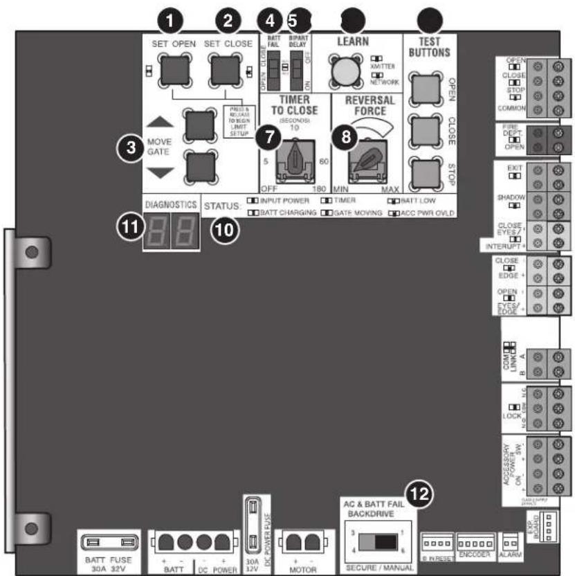
text_image
1 2 4 5 SET OPEN SET CLOSE BATT FAIL BIPART DELAY OPEN CLOSE OPEN CLOSE PRES & REACH TO BEGIN LIMIT SETUP MOVE GATE PRESS & REACH TO BEGIN LIMIT SETUP 7 TIMER TO CLOSE (SECONDS 10) 5 60 OFF 180 MIN MAX REVERSAL FORCE TEST BUTTONS OPEN CLOSE OPEN CLOSE STOPS DIAGNOSTICS STATUS: INPUT POWER TIMER BATT LOW BATT CHARGING GATE MOVING ACC PWR OVLD 11 8 9 10 12 AC & BATT FAIL BACKDRIVE AC & BATT FAIL BACKDRIVE 3 1 4 6 SECURE / MANUAL BATT FUSE 30A 32V BATT DC POWER 30A 12V DC POWER FUSE MOTOR ACCESS ENCODEX ALARMOPERATION
Reset Button
The reset button is located on the side of the control box and serves several functions:
- Press the reset button to stop a moving gate/door during a normalopen/close cycle, like a stop button.
- Press the reset button once while the gate/door is in open p disable the Timer-to-Close. The gate/door will stay in the open position. To restart the Timer-to-Close either press the reset b or activate the gate/door with a programmed remote control.
- Press the reset button to shut off the alarm and reset the
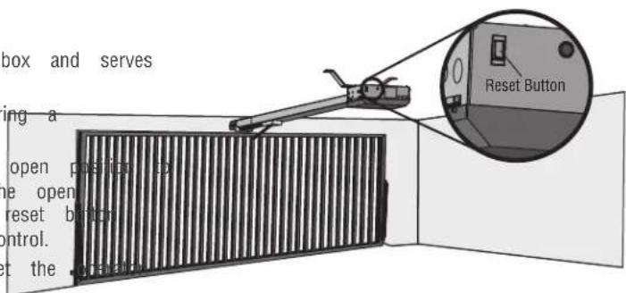
text_image
box and serves ing a open position op e open reset button control. t the .prand Reset ButtonOperator Alarm
If a contact sensor detects an obstruction twice consecutive will sound (up to 5 minutes) and the operator will need command is given after the initial 5 minutes the operator operator alarm will beep 3 times with a command if the When the inherent force of the operator (RPM/current sense following (twice consecutively) the alarm will sound (up to and the operator will need to be reset:
A. The gate/door hits an obstruction.
B. The gate/door has a broken wheel(s) or damaged track
C. The gate/door has broken springs or hardware.
D. Trolley is hitting the chassis or an unwanted object.
Remove any obstructions. Toggle the reset switch to shut and reset the operator. After the operator is reset, normal resume.
A
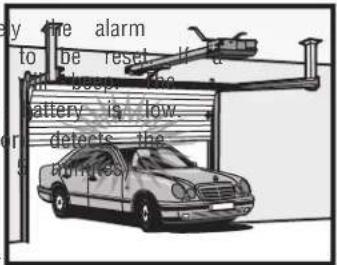
text_image
by the alarm to be reset if a the deep. The battery is low. detects the aminesB
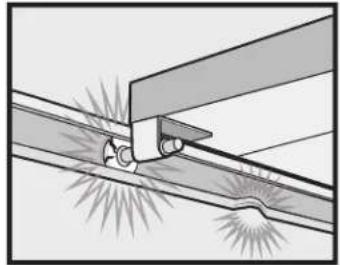
natural_image
Diagram of a mechanical joint or connection with no visible text, numbers, or symbolsC
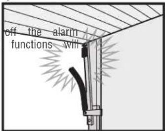
text_image
off the alarm functions willD
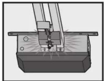
natural_image
Mechanical assembly diagram showing a cutting tool interacting with a base block (no text or symbols visible)Adjustable Open Speed
The HCTDCU provides a high speed open option to help flow in high traffic areas. Select the open speed using the BIPART DELAY switch.
BIPART DELAY OFF (default) = 8 in./sec. open speed
BIPART DELAY ON (fast) = 11 in./sec. open speed
NOTE: After changing the open speed, the force will need to be account for the change of power used, see Limit and Force Ad section.
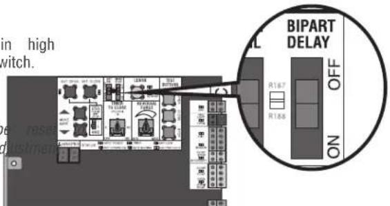
text_image
in high switch. BIPART DELAY OFF ON R1-67 R1-58Remote control
Single Button Control (SBC) Functionality
Once the remote control has been programmed the operator will operate as follows:
When gate/door is in the closed position, activation of the remote control button will open the gate/door. During the open cycle another activation of the remote control will stop the gate/door and the next activation of the remote control will close the gate/door.
When the gate/door is in the open position, activation of the remote control button will close the gate/door. If the remote control is activated while the gate/door is closing, the gate/door will stop and the next activation will open the gate/door.
OPERATION
Manual Disconnect
WARNING
To reduce the risk of SERIOUS INJURY or DEATH from a falling gate/door:
- If possible, use manual release to disengage trolley ONLY when gate/door is CLOSED. Weak or broken springs or unbalanced gate/door could result in an open gate/door falling rapidly and/or unexpectedly.
- NEVER use emergency release unless gate/door is clear of persons and obstructions.
Step 1
Insert key and turn to unlock position.
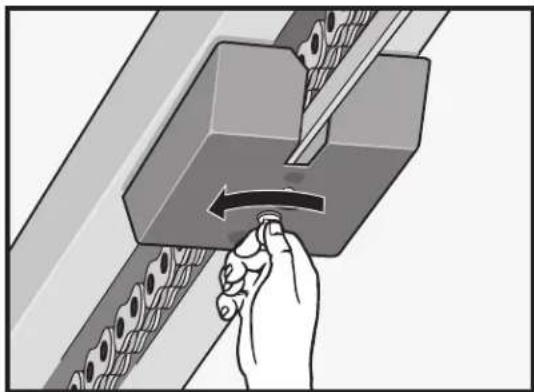
natural_image
Hand turning a button into a mechanical component with rollers (no text or symbols visible)Step 2
Pull down the release ring.
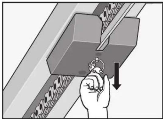
natural_image
Illustration of a hand using a tool to press or install a mechanical component, with no visible text or symbols.Step 3
Insert key and turn to unlock position.
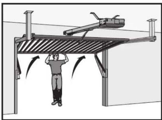
natural_image
Diagram of a person using a lift-mounted crane to lift a metal structure, with directional arrows indicating motion (no text or symbols present)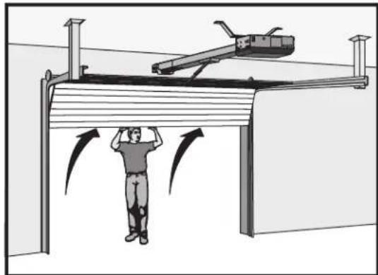
natural_image
Diagram of a person standing under a structure with motion arrows indicating movement, no text or symbols presentThe trolley will automatically re-engage when power is restored and run command is given. When the cylinder lock is in the locked position, the release ring will not disengage. If the cylinder lock is in the unlocked position, the release ring will always be accessible to disengage.
ACCESSORY WIRING
All control wiring used to connect external devices to Class 2 circuits of the operator must be (QPTZ) Power-Limited Circuit Cables, Type CL2, CL2P, CL2R, or CL2X or other cable with equivalent or better electrical, mechanical, and flammability ratings.
External Control Devices
EXIT (2 Terminals)
This input is a soft open command (maintained switch does not overirex external safeties and does not reset alarm condition). Used for exit pr telephone entry, external exit loop detector, or any device that would command the gate/door to open.
- Opens a closing gate/door and holds open an open gate/door, if maintained, pauses Timer-to-Close at OPEN limit.
SHADOW (2 Terminals)
This input is used for external shadow loop detector when loop is positioned under the swing of the gate/door.
- Holds open gate/door at open limit
- Only active when the gate/door is at the OPEN limit, disregarded at all other times
• Pauses Timer-to-Close at OPEN limit
INTERRUPT (2 Terminals)
This input is used for photoelectric sensors and external interrupt loop detector when loop is on the outside of the gate/door.
- Holds open gate/door at open limit
• Stops and reverses a closing gate/door to open limit - Pauses Timer-to-Close at OPEN limit, activates quick close and anti-tailgate features when enabled on the expansion board
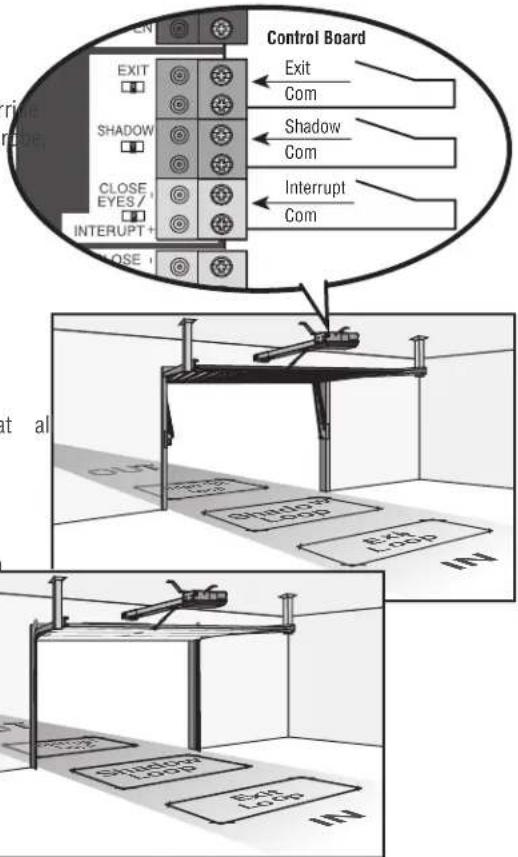
text_image
Control Board EXIT Com Shadow Com Interrupt Com EXIT SHADOW CLOSE EYES / INTERRUPT+ CLOSE at al SHADOW LOAD Exch LOAD IN1 SHADOW LOAD Exch LOAD IN2External Reset Button
The externally located reset button serves several functions:
- Press the reset button to stop a moving gate/door during a norm open/close cycle, like a stop button.
- Press the reset button once while the gate/door is in open position disable the Timer-to-Close. The gate/door will stay in the open position. To restart the Timer-to-Close either press the reset button or activate the gate/door with a programmed remote control.
- Press the reset button to shut off the alarm and reset the operator.
WIRING
- STOP and COM: Stops a moving gate/door. Hard stop (maintaining switch overrides Open and Close commands and resets alarm condition). Cancels/resets Timer-to-Close at OPEN limit. Overrides Open and Close commands (within line-of-sight)

text_image
a normal open button operator. maintained es OPEN CLOSE STOP COMMON Main Control Board Stop ComACCESSORY WIRING
Miscellaneous wiring
Three button control station (4 Terminals)
- OPEN and COM: Opens a closed gate/door. Hard open (maintained overrides external safeties and resets alarm condition). If maintained, Timer-to-Close at OPEN limit. Opens a closing gate/door and holt open gate (within line-of-sight).
- CLOSE and COM: Closes an open gate/door. Hard close (maintaining overrides external safeties and resets alarm condition within line of
- STOP and COM: Stops a moving gate/door. Hard stop (maintaining overrides Open and Close commands and resets alarm condition). Cancels/resets Timer-to-Close at OPEN limit. Overrides Open and Close commands (within line-of-sight).
Fire department open input (2 Terminals)
Acts as hard open.
Maintained input overrides (ignores) external safeties (photoelectric sensor and edge), pauses Timer-to-Close momentary input logic as single button control and safeties remain active, re-enables Timer-to-Close.
Opens a closing gate/door and holds open an open gate/door (with sight). Bypasses any pre-warning delay.
Accessory power 24 VDC, MAX 500 mA (4 Tc)
- SWITCHED: Switched ON when the gate/door is in motion. Timer-to-Close 5 second delay when the gate/door stops. The power will remain open limit when Timer-to-Close is enabled and when the Timer-to-Close counting down.
- UNSWITCHED: 24 Vdc voltage out to power accessories, always ON.
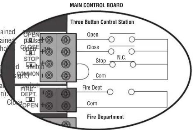
text_image
MAIN CONTROL BOARD Three Button Control Station Open Close Stop N.C. Com Fire Dept Com Fire DepartmentMAIN CONTROL BOARD
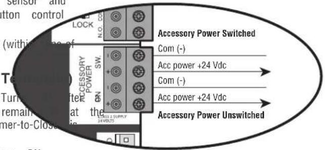
text_image
Sensor and tton control (within line of Temperature) Turn to after remain at the mer-to-Close ACCSORY POWER SW N.O. CO. N.O. CO. Accessory Power Switched Com (-) Acc power +24 Vdc Com (-) Acc power +24 Vdc Accessory Power UnswitchedACCESSORY WIRING
Red/Green Light
The RGL24LY is a low power red/green LED light accessory used to indicate the door status where upward visibility is limited.
The RGL24LY light control is directly powered from the main control board and is enabled by AUX 1 and AUX 2 switches on the expans board. See table on page 31 for red/green light functionality. The RGL24LY will run when the operator is on battery backup power.
Wiring
- Connect the COM terminal of the RGL24LY light to the terminal of ACCESSORY POWER ON on the main board.
- Connect the RED terminal of the RGL24LY to the NORMALLY (N.O.) terminal of AUX RELAY 1 on the expansion board.
- Connect the GREEN terminal of the RGL24LY to the NORMAL OPEN (N.O.) terminal of AUX RELAY 2 on the expansion be
- Connect the COM terminals of AUX RELAY 1 and 2 to the (+) terminal of ACCESSORY POWER ON on the main board. not provided.
Main control board
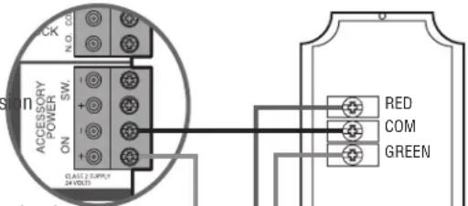
text_image
N. D. 01 SW ACCESSION POWER ON CLAST 2 SUPPLY 24 VOLT RED COM GREEN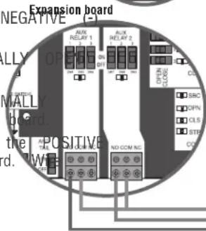
text_image
Expansion board NEGATIVE ALUX RELAY 1 ALUX RELAY 2 ALUX RELAY 3 ALUX RELAY 4 ALUX RELAY 5 ALUX RELAY 6 ALUX RELAY 7 ALUX RELAY 8 ALUX RELAY 9 ALUX RELAY 10 ALUX RELAY 11 ALUX RELAY 12 ALUX RELAY 13 ALUX RELAY 14 ALUX RELAY 15 ALUX RELAY 16 ALUX RELAY 17 ALUX RELAY 18 ALUX RELAY 19 ALUX RELAY 20 ALUX RELAY 21 ALUX RELAY 22 ALUX RELAY 23 ALUX RELAY 24 ALUX RELAY 25 ALUX RELAY 26 ALUX RELAY 27 ALUX RELAY 28 ALUX RELAY 29 ALUX RELAY 30 ALUX RELAY 31 ALUX RELAY 32 ALUX RELAY 33 ALUX RELAY 34 ALUX RELAY 35 ALUX RELAY 36 ALUX RELAY 37 ALUX RELAY 38 ALUX RELAY 39 ALUX RELAY 40 ALUX RELAY 41 ALUX RELAY 42 ALUX RELAY 43 ALUX RELAY 44 ALUX RELAY 45 ALUX RELAY 46 ALUX RELAY 47 ALUX RELAY 48 ALUX RELAY 49 ALUX RELAY 50 ALUX RELAY 51 ALUX RELAY 52 ALUX RELAY 53 ALUX RELAY 54 ALUX RELAY 55 ALUX RELAY 56 ALUX RELAY 57 ALUX RELAY 58 ALUX RELAY 59 ALUX RELAY 60RGL24LY red/green light
Custom Lights or Annunciators
Other devices can be controlled by the AUX relays in red/green warning mode. These devices require their own power source which is switched from the AUX relays. AUX 1 and 2 provide N.O and N.C options and are rated to 10A.
3rd Party Radios
Power:
- Make sure the radio is rated for 24 V (look at its namep transformer in use).
- Check for AC or DC.
- AC, AC/DC, or no polarity: Connect power wires to the ACCESSORY POWER ON terminal of the main board. DC and shows polarity: Connect the positive wire to the positive terminal of ACCESSORY POWER ON on the main board. Connect the negative wire to the negative (-) terminal of ACCESSORY POWER ON on the main board.
- The ACC PWR OVLD LED on the main board will light if problem with the radio.
Signal:
- Locate the signal wires from the receiver. There may be one
- For a single wire receiver: Connect to the positive(+) terminal desired input.
For a 2 wire receiver: Connect to the positive(+) and negative (-) terminal of the desired input.
For open-stop-close-stop operation: connect to the SBC terminal on the expansion board.
For open only operation: connect to the OPEN terminal on the expansion board or the EXIT terminal on the main board. The Timer-to-Close (TTC) must be set to close the door, see page 24.
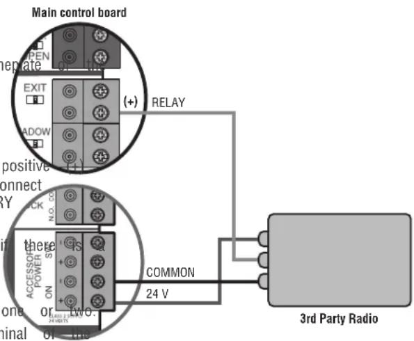
text_image
Main control board OPEN EXIT MADOW (+) RELAY positive connect RY N.0.02 there POWER ON + - TWO. COMMON 24 V in zone or ninal or 3rd Party RadioEXPANSION BOARD
CAUTION
- To AVOID damaging the circuit board, relays or accessories, DO NOT connect more than 42 Vdc (32 Vac) to the AUX relay contact terminal blocks.
Expansion Board Overview
1. QUICK CLOSE switch:
OFF: No change to the gate/door's normal operation.
6. EYE/EDGE switches:
Set the EYE/EDGE switches as needed to obtain the desired 0
ON: When CLOSE EYES/Interrupt loop is deactivated it causes CLOSE functionality.
opening or a stopped gate to close (ignores the Timer-to-Close)2, and 3 LEDs:
2. AC FAIL switch:
OPEN: Loss of AC power will cause the gate/door to o
LEDs indicating the status of the EYE/EDGE inputs. Also used
the firmware version of the expansion board:
approximately 15 seconds after AC power fail and remain
OPENLocatel the 1, 2, and 3 LEDs on the expansion board.
AC power is restored (enabling the Timer-to-Close).
- Disconnect AC/DC power to the main control board for 15
BATT: With loss of AC power, gate/door will remain in
esentseconds.
position and operator is powered from batteries.
- Connect power. The 1, 2, and 3 LEDs will flash in sequ
the main control board firmware revision is displayed. When
When set to OPEN, if the EXIT plug-in loop detector (Model
green POWER LED glows solid the LED 1 will flash the
LOOPDETLM) detects a fault, then the gate/door will open and
number then stop, then the LED 2 will flash the revision
open until fault is cleared. When set to CLOSE, then plug-in
(EXT example: For version 5.1 when the green POWER LED
detector faults are ignored (EXIT loop is faulted and inoperativ
the LED 1 will flash 5 times, then stop, then the LED :
4. ANTI-TAIL switch:
OFF: When CLOSE EYES/Interrupt loop is activated it causes
MAIN BOARD input: a closing
Input Connection for the main board connector.
gate/door to stop and reverse.
Input Closing:
ON: When CLOSE EYES/Interrupt loop is activated it causes
LE08 indicating the status of the SBC, OPN, CLS, and STP i
gate/door to pause. Once the vehicle is clear the gate/door
- Loop detector inputs:
continue to close.
Inputs for the Plug-In Loop Detectors (Model LOOPDETLM)
5. AUX RELAY switches:
Set the AUX RELAY switches as needed to obtain the 11des
wireless edge input:
as shown on the following page.
Input for the Wireless Edge Kit (Model LMWEKITU)
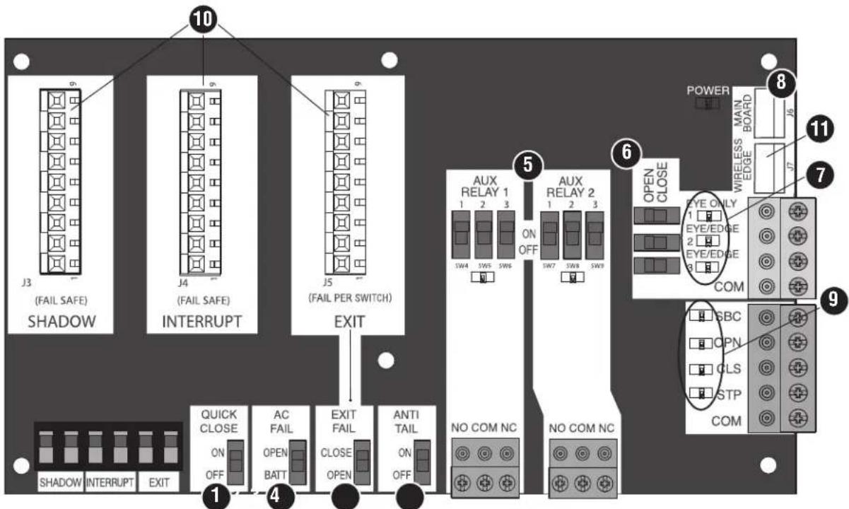
text_image
10 J3 (FAIL SAFE) SHADOW J4 (FAIL SAFE) INTERRUPT J5 (FAIL PER SWITCH) EXIT QUICK CLOSE ON OFF AC FAIL OPEN BATT EXIT FAIL CLOSE OPEN ANTI TAIL ON OFF NO COM NC NO COM NC AUX RELAY 1 1 2 3 SW4 SW5 SW6 ON OFF SW7 SW8 SW9 AUX RELAY 2 1 2 3 OPEN CLOSE EYE ONLY 1 EYE/EDGE 2 EYE/EDGE COM POWER WIRELESS MAIN BOARD J5 J7 11 7 9 SBC OPN CLS STP COMEXPANSION BOARD
Auxiliary relay 1 and 2
Normally Open (N.O.) and Normally Closed (N.C.) relay contacts to control external devices, for connection of Class 2, low voltage (42 Vdc [34 Vac] max 5 Amps) power sources only. Function of relay contact activation determined by switch settings.
| AUX RELAY SETTING | SWITCH SETTINGS | AUX RELAY 1 AUX RELAY 2 | ||
| 1 | 2 | 3 | ||
| Off (no feature selected) | OFF | OFF | OFF | Relay always off. Use this Aux Relay setting to conserve battery power. |
| Open Limit Switch | OFF | OFF | ON | Energizes at open limit. Use with SAMS (Sequenced Access Management System, jdc gate). |
| Close Limit Switch | OFF | ON | OFF | Energizes when not at close limit. For an additional audible or visual display, convoltage). |
| Gate/Door Motion | OFF | ON | ON | Energizes when motor is on (gate/door in motion). For an additional audible or v: external buzzer or light (low voltage). |
| Pre-Motion Delay | ON | OFF | OFF | Energizes 3 seconds before gate/door motion and remains energized during gate/door motion onboard alarm will sound. For an additional audible or visual display, connect an external buzzer or light (low voltage). Energizes 3 seconds before gate/door motion remains energized during gate/door motion. additional audible or visual display, connec external buzzer or light (low voltage). |
| Power | ON | ON | OFF | Energizes when AC power or solar power there is approximately a 10-12 second delay cutoff, after AC shutdown. Energizes when on battery power. There is approximately a 10-12 second delay before cutoff, after AC shutdown. |
| Tamper | ON | OFF | ON | Energizes if gate/door is manually tampered with by being pushed off of close lin audible or visual display, connect an external buzzer or light (low voltage). |
| Cycle Quantity Feedback* | ON | ON | ON | The 1, 2, and 3 LEDs will blink out (cycle count is stored on the control board/green light functionality, see below. below. |
\* Cycle count
First, note the current Aux Relay switch positions. To determine actual cycles that the gate/door operator has run (in thousand three Aux Relay switches to the ON setting for Aux Relay Expansion Board's 1, 2, and 3 LEDs will blink out the cycle LED blinking 1000's, 2 LED blinking 10,000's, 3 LED blinking 100,000's, and simultaneously all three LED's blink 1,000,000's LED blinks 3 times, 2 LED blinks 6 times, and 3 LED blink count is 163,000.). Cycle count displayed is between 1,000 and 9,999,000 cycles. After servicing, set Aux Relay switches back appropriate positions. Cycle count cannot be reset or changed. 1,000 cycles the 1, 2, and 3 LEDs will turn on for 10 s off.
NOTE: The expansion board will flash the cycle count 3 time LEDs will turn on solid for 10 seconds then turn off.
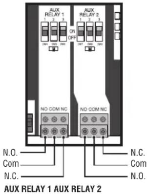
text_image
AUX RELAY 1 1 2 3 ON OFF AUX RELAY 2 1 2 3 NO COM NC. NO COM NC. N.O. Com N.C. N.C. Com N.O. AUX RELAY 1 AUX RELAY 2| RED/GREEN LIGHT FUNCTIONALITY | ||||||
| (s), Reset light wired to AUX RELAY 1. Green light wired to AUX | ||||||
| 1. The count with 1GATE STATE | AUX RELAY 1 SWITCHES | AUX RELAY 2 SWITCHES | ||||
| 1 OFF 2 OFF 3 | OFF 1 ON 2 ON | |||||
| (e.g. 1Closed) | Red light OFF* | Green light OFF | ||||
| aks once Cycle and Opening | Red light ON/Flash | Green light OFF | ||||
| to them Open | Red light OFF | Green light ON | ||||
| If un Closing | Red light ON/Flash | Green light OFF | ||||
| Second the turtur Closed Mid Stop n/a | n/a | |||||
| Undefined Mid Stop Red light ON Green light OFF | ||||||
| es then all the Timer more than seconds 5 Red light OFF Green light ON | ||||||
| Timer less than seconds 5 Red light ON/Flash Green light OFF | ||||||
| * For red light ON when gate/door is closed, set switch 1 on 1 to ON | ||||||
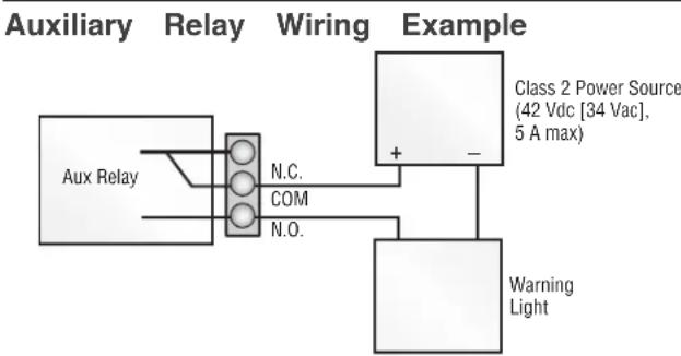
flowchart
graph TD
    A["Aux Relay"] --> B["N.C."]
    A --> C["COM"]
    A --> D["N.O."]
    E["Warning Light"] --> F["Class 2 Power Source (42 Vdc [34 Vac"], 5 A max)]
    F --> G["+"]
    F --> H["-"]
EXPANSION BOARD
Wiring Accessories to the Expansion Board
Refer to the chart below and the corresponding image for a description of the expansion board inputs.
| 1 Wireless edge | Connection for wireless edge receiver | |
| 2 Er | trapment Protection Device Inputs (4 terminals total), Open to doorClose Direction based on switch setting next to inputs | EYES ONLY Input: Open or Close Direction Photoelectric Sensors, Close: reverses fully, Open: stops open gate/doorETES/EDGE Input(s): Open or Close Direction Photoelectric Sensors, Infra-red detector wired or Edge Sensor, Close: reverses fully, Open: stops gate/door |
| 3 Single Button Control, SBC (2 terminals) | Gate command sequence - Open, Stop, Close, Stop, ... Soft Open ,Soft Close, Soft switch does not override external safeties and does not reset alarm condition) | |
| 4 Open Input (& common) (3-Button)Control Station, 4 terminals | Open command - opens a closed gate/door.total) open (maintained switch does not override external safeties and does not rese maintained, pauses Timer-to-Close at OPEN limit.Opens a closing gate/door and holds open an open gate/door. | |
| 5 Close Input (& common) (3-Button)Control Station, 4 terminals | Close command - closes an open gate/door.total) close (maintained switch does not override external safeties and does not rese | |
| 6 Stop Input (& common) (3-PB station, 4 terminals total) | Stop command - stops a moving gate/door.Hard stop (maintained switch overrides Open and Close commands and resets alarm maintained, pauses Timer-to-Close at OPEN limit.Overrides an Open or Close command. | |
| 7 Exit Loop Input (2 terminals) | Loop wire connection for plug-in loop detector when loop is inside secured area in Open command - opens a closed gate/door.Soft open (maintained switch does not override external safeties and does not rese maintained, pauses Timer-to-Close at OPEN limit.Opens a closing gate/door and holds open an open gate/door. | |
| 8 Shadow Loop Input (2 terminals) | Loop wire connection for plug-in loop detector when loop is positioned under the Holds open gate/door at open limitDisregarded during gate/door motionPauses Timer-to-Close at Open Limit | |
| 9 Interrupt Loop Input (2 terminals) | Loop wire connection for plug-in loop detector when loop is along the side of the Holds open gate/door at open limitStops and reverses a closing gate/doorPauses Timer-to-Close at Open Limit | |
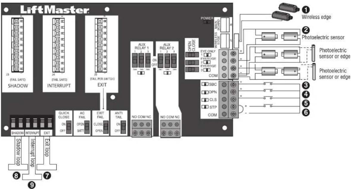
text_image
LiftMaster 13 (FAIL SAFE) SHADOW 24 (FAIL SAFE) INTERRUPT J5 (FAIL PER SWITCH) EXIT AUX RELAY 1 1 2 3 ON OFF AUX RELAY 2 1 2 3 OPEN CLOSE EYE ONLY 1 EYE/EDGE 2 EYE/EDGE 3 COM SBC OPN CLS STP COM Wireless edge Photoelectric sensor Photoelectric sensor or edge Photoelectric sensor or edge NO COM NC NO COM NC QUICK CLOSE ON OFF AC FAIL OPEN BATT EXIT FAIL ANTI TAIL ON OFF SHORT INTERRUPT EXIT LOOP Shadow loop 8 9 POWER MAIN BOARD 17 16 15 14 13 12 11 10 9 ① Wireless edge ② Photoelectric sensor ③ Photoelectric sensor or edge ④ Photoelectric sensor or edgeMAINTENANCE
IMPORTANT SAFETY INSTRUCTIONS
WARNING
To reduce the risk of SEVERE INJURY or DEATH:
- READ AND FOLLOW ALL INSTRUCTIONS.
- ANY maintenance to the operator or in the area near MUST NOT be performed until disconnecting the electric (AC or solar and battery) and locking-out the power power switch. Upon completion of maintenance the area cleared and secured, at that time the unit may be
- NEVER let children operate or play with gate controls. remote control away from children.
- ALWAYS keep people and objects away from the gate/ SHOULD CROSS THE PATH OF THE MOVING GATE/DO
- The entrance is for vehicles ONLY. Pedestrians MUST entrance.
- Test the gate/door operator monthly. The gate/door MUST reverse the operator contact with an object or reverse when an object activates the power contact sensors. After adjusting the force or the limit of tria retest the gate operator. Failure to adjust and retest the gate/door MUST be properly can increase the risk of INJURY or DEATH. Turned the seminal disconnect release ONLY when the gate/door is
- KEEP GATES/DOORS PROPERLY MAINTAINED. Read the owner's manual. Have a qualified service person make repairs to gate/do door, one hardware.
use Activate gate/door ONLY when it can be seen clearly, is properl adjusted and there are no obstructions to gate/door travel.
• To reduce the risk of FIRE or INJURY to persons use ONLY part 29-NP712 for replacement batteries.
- SAVE THESE INSTRUCTIONS.
CAUTION
- ALWAYS wear protective gloves and eye protection when changing the battery or working around the battery compartment.
Maintenance Chart
Disconnect all power (AC, solar, battery) to the operator before servicing. The operator's AC Power switch ONLY turns off AC power to the control board and DOES NOT turn off battery power. ALWAYS disconnect the batteries to service the operator.
| DESCRIPTION TASK | CHECK AT LEAST ONCE EVERY | |||
| MONTH | 6 MONTH$ | 3 YEAR | ||
| Entrapment Protection Devices | Check and test inherent (built into the operator) and external proper operation | devXes | for | |
| Warning Signs | Make sure they are present and replace if worn or broken, | see X Accessories | ||
| Manual Disconnect Check and test for proper operation X | ||||
| Gate/Door | Inspect for wear or damage; ensure it still complies with ASTM XF220 page 5 | 0, see | ||
| Gate/Door Track | Make sure the gate/door track runs smoothly. | X | ||
| Accessories | Check all for proper operation | X | ||
| Electrical | Inspect all wire connections | X | ||
| Operator | Inspect for wear or damage | X | ||
| Chain | For chain maintenance, adjust the turnbuckle. | X | ||
| Batteries | Replace | X | ||
Batteries
Batteries will degrade over time depending on temperature and usage. The operator alarm will beep 3 times with a command if the battery is low. Batteries do not perform well in extremely cold temperatures. For best performance, the batteries should be replaced every 3 years. Use only LiftMaster part 29-NP712 for replacement batteries. The batteries contain lead and need to be disposed of properly.
The operator comes with two 7AH batteries.
TROUBLESHOOTING

WARNING
To protect against fire and electrocution:
- DISCONNECT power (AC or solar and battery) BEFORE installer only with fuse of same type and rating. servicing operator.
Diagnostic Codes
NOTE: When cycling or disconnecting power (ac/dc) to the control board, it is recommended that you unplug the J15 plug.
To View the Codes
The codes will show on the diagnostic display.
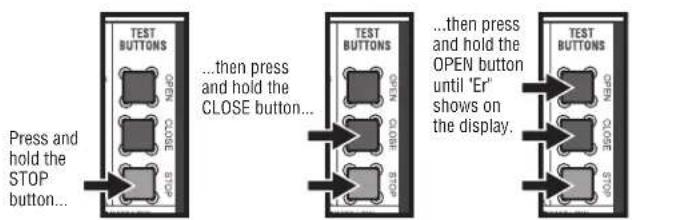
text_image
Press and hold the STOP button... ...then press and hold the CLOSE button... ...then press and hold the OPEN button until 'Er' shows on the display. TEST BUTTONS OPEN CLOSE STOP TEST BUTTONS OPEN CLOSE STOPThe operator will show the code sequence number followed number:
CODE SEQUENCE NUMBER
The first number shown is the most recent code (example: "01"). The display will show the sequence of codes that occurred starting with '01' and going up to code '20'.

A SECOND LATER....
CODE NUMBER
The second number shown after the code sequence number is the code itself (31-99, example '31'). Refer to the chart on the following page for an explanation of each code.

To Scroll Through the Saved Codes
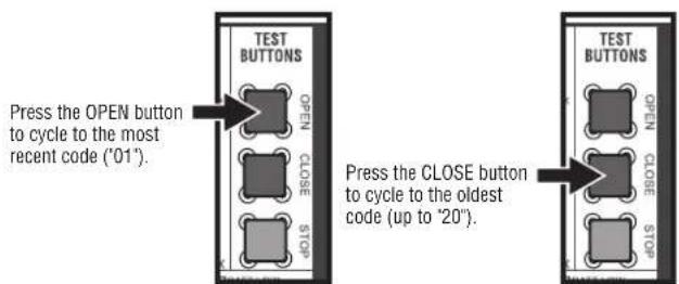
text_image
TEST BUTTONS OPEN CLOSE STOP Press the OPEN button to cycle to the most recent code ("01"). Press the CLOSE button to cycle to the oldest code (up to "20"). TEST BUTTONS OPEN CLOSE CLOSE STOPThe operator will only keep track of up to 20 codes, then will start saving over the oldest codes as new codes occur.
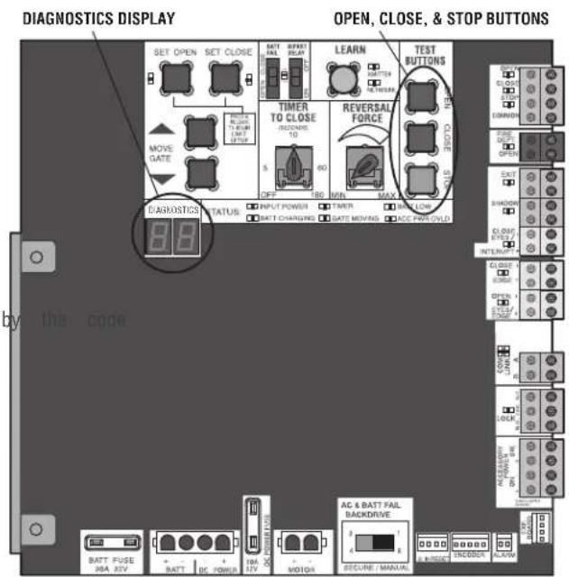
text_image
DIAGNOSTICS DISPLAY SET OPEN SET CLOSE MOVE GATE BATT FUSE 38A 24V BATT BC POWER 10A 12V MOTOR AC & BATT FAIL BACKDRIVE SECURE MANUAL OPEN, CLOSE, & STOP BUTTONS LEARN TIMER TO CLOSE RCDING: 10 5 60 OFF 180 MIN MAX REVERSAL FORCE CLOSE DOWN CLOCK TICKER BEANS FIRE OR OPEN EXIT SHADOW CLOSE DIP COLD INTERRUPT CLOSE DIP COLD DIP COLD DIP COLD DIP COLD DIP COLD DIP COLD DIP COLD DIP COLD DIP COLD DIP COLD DIP COLD DIP COLD DIP COLD DIP COLD DIP COLD DIP COLD DIP COLD DIP COLD DIP COLD DIP COLD DIP COL DIP COLD DIP COLD DIP COLD DIP COLD DIP COLD DIP COLD DIP COLD DIP COLD DIP COLD DIP COLD DIP COLD DIP COLD DIP COLD DIP COLD DIP COLD DIP COLD DIP COLD DIP COLD DIP COLD DIP CCL DIP COLD DIP COLD DIP COLD DIP COLD DIP COLD DIP COLD DIP COLD DIP COLD DIP COLD DIP COLD DIP COLD DIP COLD DIP COLD DIP COLD DIP COLD DIP COLD DIP COLD DIP COLD DIP COLD DIP CRED DIP COLD DIP COLD DIP COLD DIP COLD DIP COLD DIP COLD DIP COLD DIP COLD DIP COLD DIP COLD DIP COLD DIP COLD DIP COLD DIP COLD DIP COLD DIP COLD DIP COLD DIP COLD DIP COLD DIP COLO DIP COLO DIP COLO DIP COLO DIP COLO DIP COLO DIP COLO DIP COLO DIP COLO DIP COLO DIP COLOTo Exit
Press and release the STOP button to exit. The display will also after two minutes of inactivity.
To Reset the Code History
- Press and hold the STOP button for six seconds. The display show "Er" then "CL" alternately for six seconds.
- Release the STOP button. The code history has now been re: display will show "-" until a new code occurs.
- Press and release the STOP button to exit.
TROUBLESHOOTING
Diagnostic Codes Table
Some codes are saved in the code history and some are not. If a code is not saved it will briefly appear on the display as it occurs, then disappear.

LiftMaster System

led Sy
em
Informa


External Entrapmen
Protection

Inherent Entrapment
Protection
| Code | Meaning Solution Saved | ||
| 31 | Main control board has experienced an in failure. | Disconnect all power, wait 15 seconds, then reconnect power (Noboot). If issue continues, replace main control board. | |
| 34 | Absolute Position Encoder Error, not getting position information from encoder | Check APE assembly and wiring connections. Replace the APEYAssembly if necessary. | |
| 35 | Max-Run-Time Exceeded Error Check for an obstruction, then reprogram the limits. YES | ||
| 36 | Product ID Error Was the control board | just replaced? If so, erase limits, enter limit setup mode and set limits. If not, disconnect all power, wait 15 seconds, then reconnect power before changing product ID harness. | YES |
| 37 | Product ID Failure Unplug product ID harness then plug back in. Disconnect all power, wait 15 seconds, then reconnect power before replacing product ID harness. | ||
| 38 | Hard Stop Limit Limit may be set too | tightly against a non-resilient hard stop (re-adjust limit). Operator may be at end of travel (re-adjust mounting). | NO |
| 40 | Battery overvoltage | Too much voltage on the battery. Check harness. Make 24V battery on a 12V system. | sure |
| 41 | Battery overcurrent | Possible short of the battery charge harness. Check harness. Make sure you do NOT have a 12V battery on a 24V system. | |
| 42 | No battery at boot up | Check battery connections and installation. Replace batteries if depleted to less than 20V on a 24V system or less than 10V on a 12V system. | YES |
| 43 | Exit Loop Error | Failure or missing loop (SHORT or OPEN - LiftMaster Detector only) Check loop wiring throughout connection. May in the loop, or an open connection in the loop. | Loop |
| 44 | Shadow Loop Error | ||
| 45 | Interrupt Loop Error | ||
| 46 | Wireless edge battery low | Replace batteries in wireless edge. | |
| 50 | Door out of balance detected | Check counterbalance spring condition and setting. | YES |
| 53 | Brownout occurred | AC/DC board supply dipped below allowable level. Review power supply and wiring. If rebooting, ensure enough time for discharge force a fresh boot. | |
| 60 | Minimum number of monitored entrapment protection devices not installed. | Review monitored entrapment protection device connections. Vertical gate/door operators require the installation of the first external No monitored entrapment protection device in the close direction to function. | |
| 61 | CLOSE EYE/INTERRUPT held more than 3 minutes | minutes | |
| 62 | CLOSE EDGE held more than 3 minutes | Check wired input on main control board; check for alignment or obstruction. | YES |
| 63 | OPEN EYE/EDGE held more than 3 minutes | ||
| 64 | CLOSE EYE/INTERRUPT held more than 3 minutes | minutes | |
| 65 | CLOSE EYE/EDGE held more than 3 minutes | Check wired input on expansion board; check for alignment or obstruction. | YES |
| 66 | OPEN EYE/EDGE held more than 3 minutes | ||
| 67 | Wireless edge triggered more than 3 minutes | Check wired input for wiring issue or obstruction. | YES |
| 68 | Wireless edge loss of monitoring | Check wireless edge inputs. | |
| 69 | Wireless edge triggered | If an obstruction occurred, no action required. If an obstruction did NOT occur, check inputs and wiring. | NO |
TROUBLESHOOTING
| Code | Meaning Solution Saved | ||
| 70 | CLOSE EYE/INTERRUPT triggered, causing reversal, preventing close, or resetting TTC | NOF an obstruction occurred, no action required. If an obstruction did occur, check alignment, inputs, and wiring on main control board or | NO |
| 71 | CLOSE EDGE triggered, causing reversal, preventing close, or canceling TTC | ||
| 72 | OPEN EYE/EDGE triggered, causing reversal preventing opening | ||
| 73 | CLOSE EYE/INTERRUPT triggered, causing reversal, preventing close, or resetting TTC | IFandn obstruction occurred, no action required. If an obstruction did occur, check alignment, inputs, and wiring on expansion board. or | NO |
| 74 | CLOSE EYE/EDGE triggered, causing reversal preventing close or canceling TTC | ||
| 75 | OPEN EYE/EDGE triggered, causing reversal preventing opening | ||
| 82 | Close input (EYE/EDGE) communication fault (expansion board) | Check the connections between the main board and the expansion | No |
| 83 | Open input (EYE/EDGE) communication fault (expansion board) | ||
| 84 | Non-monitored device detected on the wireless safety system | Non-monitored contact closure devices are not supported. Make sure connected devices are monitored. Check edges for proper orientation resistive end cap connection. | Yes |
| 91 | Force Reversal | Check for obstruction. If no obstruction, check that the mechanical assembly is engaged and free to move. See section on Limited Adjustment, and Obstruction Test. | Yes |
| 93 | RPM / STALL Reversal | Check for obstruction. If no obstruction, check the operator that the mechanical assembly is engaged and free to move. Yes | Yes |
| 99 | Normal Operation No action required YES | ||
TROUBLESHOOTING
Control Board LEDs
| STATUS LEDS | ||
| INPUT POWER | OFF OFF state | |
| ON AC charger | or Solar power available | |
| BATT CHARGING | OFF Not charging | |
| ON Three stage | battery charging | |
| TIMER | OFF The timer is disabled | |
| ON The timer is enabled | ||
| MEDIUM BLINK (The timer is running blink per second) | ||
| FAST BLINK (2 blinks per second) | The timer is paused | |
| FASTEST BLINK (the timer is canceled blinks per second) | ||
| GATE/DOOR MOVING | OFF The gate/door is stopped | |
| ON The gate/door is opening or closing | ||
| MEDIUM BLINK (Operator is in E1 (single blink per second) entrapment) | ||
| FASTEST BLINK (the operator is in E2 (double blinks per second) entrapment) | ||
| BATT LOW | OFF No battery error | |
| ON Battery low | ||
| BLINK (1 blink second) | Battery critically low | |
| ACC PWR OVLD | OFF OFF state | |
| ON Accessory overload protector opened | ||
| INPUT LEDS | ||
| OPEN, CLOSE, STOP INPUT | OFF Input | inactive |
| ON Input | active | |
| BLINK Input | active on other operator | |
| FIRE DEPT INPUT | JTOFF Input | inactive |
| ON Input | active | |
| BLINK Input | active on other operator | |
| EXIT | OFF Input | inactive |
| ON Input | active | |
| BLINK Input | active on other operator | |
| SHADOW | OFF Input | inactive |
| ON Input | active | |
| BLINK Input | active on other operator | |
| CLOSE EYES/INTERRUPT | OFF Input | inactive |
| ON Input | active | |
| BLINK Input | active on other operator | |
| CLOSE EDGE | OFF Input | inactive |
| ON Input | active | |
| BLINK Input | active on other operator | |
| OPEN EYES/EDGE | OFF Input | inactive |
| ON Input | active | |
| BLINK Input | active on other operator | |
| LOCK | OFF Maglock relay inactive | |
| ON Maglock relay active | ||
STATUS LEDS INPUT LEDS
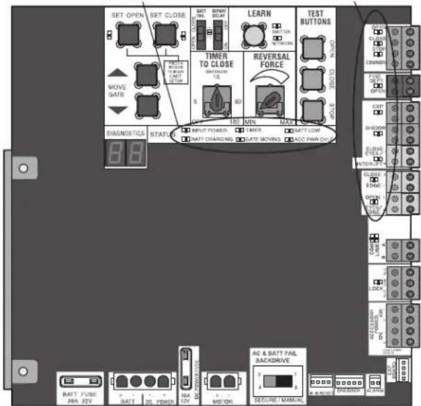
text_image
SET OPEN SET CLOSE MAKE SIZE 30.0 MP MOVE GATE TIME TO CLOSE 5 60 150 MIN MAX REVERSAL FORCE TEST BUTTONS OPEN CLOSE 8.8 BAGNDSTIGS STARTS INPUT POWER TIME BATT LOW BATT CHARGING DATE MOVING ADD PIN ON AC & BATT FAIL BACKDRIVE BATT FUSE JBA J2V BATT 2G PEMBER NBA J2V MO'ON BEGRICUM CONTROL ACCESSOR ON CLOCK SHORT CLOSURE RANGE ON ON ON ON ON ON ON ON ON ON ON ON ON ON ON ON ON ON ON ON ON ON ON ON ON ON ON ON ON ON ON ON ON ON ON ON ON ON ON ON ON ON ON ON ON ON ON ON ON ON OnTROUBLESHOOTING
Troubleshooting Chart
| SYMPTOM POSSIBLE CAUSES SOLUTIONS | ||
| Operator does not run and diagnostic display not on. | a. No power to control boardb. Open fusec. If on battery power only, low or batteriesd. Defective control board | a. Check AC and battery powerb. Check fusesdeadCharge batteries by AC or solar power or replace batteriesd. Replace defective control board |
| Control board powers up, but motor does not run. | a. Reset switch is stuckb. Stop button active or jumper not for stop circuitc. If on battery power only, low or batteriesd. Open or Close input activee. Entrapment Protection Device activef. Vehicle loop detector or probe actvg. Defective control board | a. Check reset switchib. Check Stop button is not “stuck on”, or verify that the stop b normally closed circuit, or put a jumper on the stop circuit.deadCharges batteries by AC or solar power or replace batteriesd. Check all Open and Close inputs for a “stuck on” inpute. Check all Entrapment Protection Device inputs for a “stuck on” sf. Check all vehicle detector inputs for a “stuck on” detectorg. Replace defective control board |
| Gate/door moves, but cannot set correct limits. | a. Gate/door does not move to a limitb. Gate/door is too difficult to movec. Limits are set too close (slide gate applications only) | b. Positionmanual disconnect, manually move gate/door, and ensure gate moves easily limit to limit. Repair gate/door as needed.Gate/door must move easily and freely through its entire limit. Repair gate/door as needed.c. Ensure the gate/door moves at least four feet between the OPEN the CLOSE limit. |
| Gate/door does rota fully open or fullyb. Gate/door is too difficult to move close when setting limits. | a. Gate/door does not move to a limitb. Gate/door is too difficult to move close when setting limits. | b. Positionmanual disconnect, manually move gate/door, and ensure gate moves easily limit to limit. Repair gate/door as needed.b. Gate/door must move easily and freely through its entire limit. Repair gate/door as needed. |
| Operator does not respond to a wired LEDs control/command (example: Open, Close, SBC, etc.) | a. Check Open and Close command b. Stop button is activec. Reset button is stuckd. If on battery power only, low or batteriese. Entrapment Protection Device activef. Vehicle loop detector or vehicle probe active | input Check all Open and Close inputs for a “stuck on” inputb. Check Stop button is not “stuck on”c. Check Reset buttond. Charges batteries by AC or solar power or replace batteries deadCheck all Entrapment Protection Device inputs for a “stuck on” sf. Check all vehicle detector inputs for a “stuck on” detector |
| Operator does not respond to a wireless control transmitter | a. Check XMITTER LED when wireless control is activeorb. Stop button is activec. Reset button is stuckd. Poor radio reception | a. Activate wireless control and check XMITTER LED is on. wireless control/transmitter to control board. Replace wireless control needed.b. Check Stop button is not “stuck on”c. Check Reset buttond. Check if similar wired control operates correctly. Check if wireless controls works properly when within a few feet of operator. Check operator’s antenna and antenna wire. Check other wireless devices. |
| Gate/door stops during travel and reverses immediately. | a. Control (Open, Close) becoming activb. Vehicle loop detector activec. Low battery voltage | a. Check all Open and Close inputs for an active inputb. Check all vehicle detector inputs for an active detectorc. Battery voltage must be 23.0 Vdc or higher. Charge batteries by solar power or replace batteries |
TROUBLESHOOTING
| SYMPTOM POSSIBLE CAUSES SOLUTIONS | ||
| Gate/door opens,but will not close with transmitterTimer-to-Close. | a.Open control activeb.Vehicle loop detector activorc.Loss of AC power with AC FAIL OPENd.Low battery with LOW BATT sete.Fire Dept input activef.Timer-to-Close not setg.Close Entrapment Protection Device | a.Check all Open inputs for an active inputb.Check all vehicle detector inputs for an active detectorsetCheck AC power and AC Fail option settingd.Check if AC power is available. If no AC power, then to OP batteries and battery voltage must be 23.0 Vdc or higher. Charge batteries by AC or solar power or replace batteries.e.Check Fire Dept inputactiveCheck Timer-to-Close (TTC) settingg.Check all Entrapment Protection Device inputs for an active senso |
| Gate/door closes,but will not open | a.Vehicle loop detector activeb.Low battery with LOW BATT optionCLOSE | a.Check all vehicle detector inputs for an active detectorb.setCheck if AC power is available. If no AC power, then batteries and battery voltage must be 23.0 Vdc or higher. Charge batteries by AC or solar power or replace batteries. |
| Exit loop activation does not cause gate/door to open | a.Exit vehicle detector setup incorrectlyb.Defective Exit loop detectorc.Low battery with LOW BATT optionCLOSE | a.Review Exit loop detector settings. Adjust settings as needed.b.Replace defective Exit loop detector.csetCheck if AC power is available. If no AC power, then batteries and battery voltage must be 23.0 Vdc or higher. Charge batteries by AC or solar power or replace batteries. |
| Interrupt loop does not cause gate/door to stop and reverse. | esa.Vehicle detector setup incorrectlyb.Defective vehicle loop detectorc.Anti-tail set to ON | a.Review Interrupt loop detector settings. Adjust settings asb.Replace defective Interrupt loop detector.c.Set anti-tail to OFF. |
| Shadow loop does not keep gate/door at open limit. | a.Vehicle detector setup incorrectlyb.Defective vehicle loop detector | a.Review Shadow loop detector settings. Adjust settings asb.Replace defective Shadow loop detector. |
| Obstruction in gate/door's path does not cause gate/door to stop and reverse. | a.Force adjustment needed a.Refer | to the Adjustment section to conduct the obstruction test and perform the proper force adjustment that is needed. |
| Photoelectric sensor does not stop or reverse gate/door. | a.Incorrect photoelectric sensor wiringb.Defective photoelectric sensor | a.Check photoelectric sensor wiring. Retest that obstructing photoelect sensor causes moving gate/door to stop, and may reverse directionb.Replace defective photoelectric sensor. Retest that obstructing photoelectric sensor causes moving gate/door to stop, and may re direction. |
| Edge Sensor does not stop or reverse gate/door. | a.Incorrect edge sensor wiringb.Defective edge sensor | a.Check edge sensor wiring. Retest that activating edge sensor causing moving gate/door to stop and reverse direction.b.Replace defective edge sensor. Retest that activating edge moving gate/door to stop and reverse direction. |
| Alarm sounds for minutes or alarm sounds with a command. | aDouble entrapment occurred (two obstructions within a single activation) | a.Check for cause of entrapment (obstruction) detection and the reset button to shut off alarm and reset the operator. |
| Alarm beeps three times with a command. | a.Low battery a.Check if AC power | is available. If no AC power, then running on batteries and battery voltage must be 23.0 Vdc or higher. Charge batteries by AC or solar power or replace batteries |
| Alarm beeps when running. | a.Expansion board settingb.Constant pressure to open or close | a.Pre-warning is set to "ON"bis Cginstant pressure to open or closed is given |
| Expansion board function not controlling gate/door. | a.Defective main board to expansionb.wiringb.Incorrect input wiring to expansionc.Defective expansion board or defective main board | a.Check main board to expansion board wiring. If required, cable.boardCheck wiring to all inputs on expansion board.Replace defective expansion board or defective main board |
TROUBLESHOOTING
| SYMPTOM POSSIBLE CAUSES SOLUTIONS | ||
| Switched (SW)Accessory power remaining on. | a. In limit setup mode a. Learn the | limits |
| Accessories connected to Switch (SW)Accessory power not working correctly, turning off, or resetting. | a. Normal behavior a. Move accessory | to accessory power "ON" |
| Accessories connected to Accessory power not working correctly, turning off, or resetting. | a. Accessory power protector activeb. Defective control board | a. Disconnect all accessory powered devices and measure accessory p voltage (should be 23 - 30 Vdc). If voltage is correct, connect accessories one at a time, measuring accessory voltage after every connection.b. Replace defective control board |
| Quick Close not working correctly. | a. Quick Close setting incorrectb. Interrupt loop detectorc. Defective Expansion board | a. Check that Quick Close setting is ONb. Check operation of Interrupt Loop detectorc. Replace defective Expansion board |
| Anti-Tailgating not working correctly. | a. Anti-Tail setting incorrectb. Interrupt loop detectorc. Defective Expansion board | a. Check that Anti-Tail setting is ONb. Check operation of Interrupt Loop detectorc. Replace defective Expansion board |
| AUX Relay not working correctly. | a. AUX Relay setting incorrectb. AUX Relay wiring incorrectc. Defective Expansion board | a. Check AUX Relay switches settingsb. Check that wiring is connected to either N.O. and COM or to COM.c. Set AUX Relay to another setting and test. Replace defective exp board. |
WIRING DIAGRAM

WARNING
To protect against fire and electrocution:
- DISCONNECT power (AC or solar and battery) BEFORE installer only with fuse of same type and rating. servicing operator.
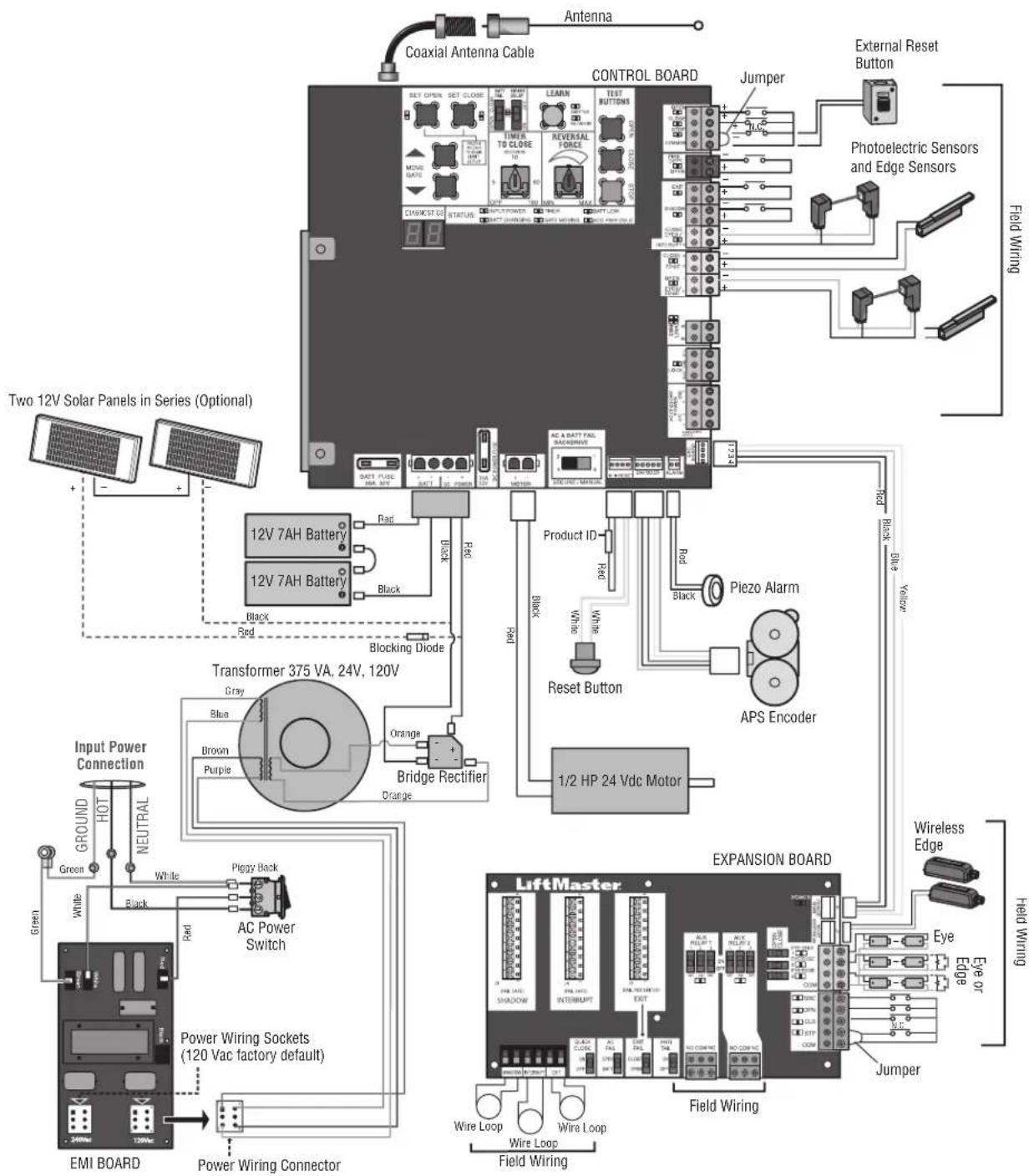
text_image
Operator Cover K10-37598 Chassis and Cover K75-38058 Mounting Plate K10-37641 Toroid Transformer K204C0211 Motor 24Vdc K76-38732 EMI Board 120V/240V K1D7078 Gear Reducer (28:1) K32-37560-3 Arm Assembly K75-50146 Curved Door Arm K10-10203 Arm Bushing K77-50153 Alternative Door Mounting Bracket 10-10204 Arm Bracket K09-50152 Rubber Isolator K75-50150 Header Bracket K10-50154 Main Control Board K1D8389-1CC Battery Access Door K10-37595 Expansion Board K1D8367-1CC NOT SHOWN K94-37205 Battery Harness (for 7AH batteries) K94-34778 Board to board wire harness (main board to expansion board) K94-37806 Reset switch with ID resistor K40-38471 U.L. Warning Sign K94-36891 7AH Solar Battery Harness Two 7AH batteries K74-30762 Output Sprocket K15-41B17LKGH Single Battery 7AH, 12 Vdc 29-NP712 Turn Buckle K75-50132 Rail 8' (2.4 m) - HCT08 10' (3.1 m) - HCT10 12' (3.7 m) - HCT12 14' (4.3 m) - HCT14 16' (4.9 m) - HCT16 Trolley Wheels K13-50141 Retaining Ring Clip K87-E-050 Trolley Wheel Shaft K11-50136 Trolley Body Assembly K75-50147 Idler Sprocket Cover K10-50151 Idler Sprocket K75-50149 Chain Guard K10-37955 Vented Plug K80-38735 Alarm K94-36411 Bridge Rectifier K52C0481 Chain #41 (10' [3.1 m] per box) 19-41240D Antenna K77-36541 Chain Coupling Release K07-50215 Key Release K80-50142 Release Ring K80-50145 Key K80-50295 Trolley Latch K75-50138 Plastic Plug K80-20078 Trolley Cover K09-50756ACCESSORIES
Entrapment Protection
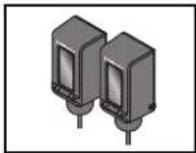
LiftMaster monitored through beam photoelectric sensor
Model LMTBUL
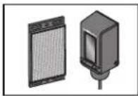
LiftMaster monitored retro-reflective photoelectric sensor
Model LMRRUL
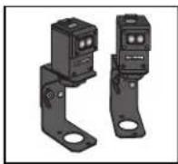
LiftMaster Monitored Commercial Protector System®
Models CPS-UN4 and CPSUN4G
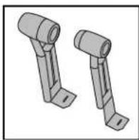
natural_image
Two identical mechanical bracket components with flanged ends, shown in 3D rendering (no text or symbols)LiftMaster Monitored Dual-Side Photoelectr Sensors
Model CPS-OPEN4
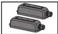
LiftMaster monitored wireless edge kit (transmitter and receiver)
Model LMWEKITU
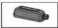
LiftMaster monitored wireless edge transmitter
Model LMWETXU
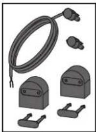
natural_image
Illustration of various electrical connectors and components (no text or symbols visible)Large profile monitored edge (82 ft.
Model L50
Large profile ends kit (10 pair)
Model L50E
Small profile monitored edge (82 ft.
Model S50
Small profile ends kit (10 pair)
Model S50E
Optical Edge System
Model OES-SD16
For a full list of optical edges see LiftMaster.com
PVC Channel
1-3/4" x 1-3/4" - Model OES-4504
2" x 2" - Model OES-5104
Plastic channel
8 ft. (2.4 m) for both small and large profile edges (pack of 10).
Model L50CHP
Aluminum channel
10 ft. (3.1 m) for both small and large edge profiles (pack of 8).
Model L50CHAL
LiftMaster large profile monitored edges (4ft.,5ft., 6ft.)
Model L504AL, L505AL, L506AL
Edge cutting tool
Model ETOOL
Remote Controls
LiftMaster offers a variety of LiftMaster remote controls to satisfy you application needs. Single-button to 4-button, visor or key chain. The following remote controls are compatible with operators manufactured by LiftMaster after 1993. Contact your authorized LiftMaster dealer for add details and options.
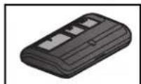
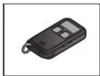
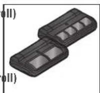
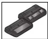
3-button remote control
The 3-button remote control can be programmed t control the operator. Includes visor c
Model 893MAX
3-button mini-remote control
The 3-button remote control can be programmed t-control the operator. Includes key ring and fastenir strip.
Model 890MAX
Security+ 2⑨learning remote controls
One button can control a gate operator and the (s) can control garage door(s). It can also be programmed to Security+ Security+ 2.0 code format.
Models 892LT and 894LT
Universal single and 3-button remote controls
Ideal for applications requiring a large number of remote controls.
Models 811LM and 813LM
ACCESSORIES
Miscellaneous
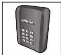

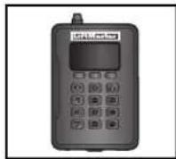
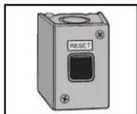
Wireless commercial keypad
Durable wireless keypad with blue LED backlight metal keypad, zinc-alloy metal cover and 5 year 9V lithium battery. 2.0 ^® compatible.
Model KPW250
LiftMaster® internet gateway
Internet enabled accessory which connects the computer and allows you to monitor control gate operators and lighting access enabled by Myotechnology. Model 828LM
Commercial access control receiver
Access control receiver for up to 1,000 (any combination of remote controls and wireless keyless entries). Model STAR1000
Red/Green Traffic Light
Indicates when a gate/door or door rea open position. Provides assurance of saf entering and exiting of the facility, redu potential for costly accidents. Model RGL24LY
External Reset Button
Model UNISW
Remote antenna extension kit
The remote antenna extension kit allows antenna to be remotely installed. Model 86LM

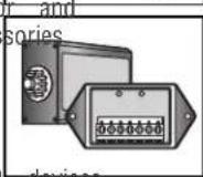
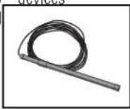
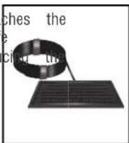
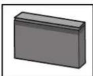
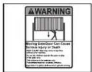
Commercial access control receiver
Access control receiver for up to 1,000 devices (ar combination of remote controls and wireless keyless entries).
Model STAR1000
Plug-in loop detector
Low power. Conveniently plugs into existing control board. Model LOOPDETLM
Loop Detector
Low power loop detectors mounted and wired separately inside control box. LiftMaster low power accessory. Model LD7LP
Vehicle sensing probe
The vehicle sensing probe is buried in the ground and can detect a car as it approaches and will open the gate. Model CP3
Solar panel kit
This kit is to replace or add a solar panel to t operator application. 60W maximum for 24 Vdc operators and 30W maximum for 12 Vdc operators. Requires a 33AH battery harness. Models SP10W12V (10 Watt, 12V) and SP20W12V (20 Watt, 12V)
7AH batteries
Standard 7 AMP-Hour Battery, 12 Vdc, to replace original batteries provided with operator. Reuse existing harnesses. Models 29-NP712 (1) and K74-30762 (2)
LiftMaster Cloud™ connected access protocol - high capacity Model CAPXL
Warning sign
Model 40-50564
WARRANTY
Five Year Commercial Limited Warranty
LiftMaster ("Seller") warrants to the first purchaser of this product, for the structure in which this product is originally installed, that it is free from defect in materials and/or workmanship for a period of 5 year commercial from the date of purchase [and that the HCTDCUL is free from defect in materials and/or workmanship for a period of 5 year commercial from the date of purchase]. The proper operation of this product is dependent on your compliance with the instructions regarding installation, operation, maintenance and testing. Failure to comply strictly with those instructions will void this limited warranty in its entirety.
If, during the limited warranty period, this product appears to contain a defect covered by this limited warranty, call 1-800-528-2806, toll free, before dismantling this product. Then send this product, pre-paid and insured, to our service center for warranty repair. You will be advised of shipping instructions when you call. Please include a brief description of the problem and a dated proof-of-purchase receipt with any product returned for warranty repair. Products returned to Seller for warranty repair, which upon receipt by Seller are confirmed to be defective and covered by this limited warranty, will be repaired or replaced (at Seller's sole option) at no cost to you and returned pre-paid. Defective parts will be repaired or replaced with new or factory-rebuilt parts at Seller's sole option.
ALL IMPLIED WARRANTIES FOR THE PRODUCT, INCLUDING BUT NOT LIMITED TO ANY IMPLIED WARRANTIES OF MERCHANTABILITY AND FITNESS FOR A PARTICULAR PURPOSE, ARE LIMITED IN DURATION TO THE 5 YEAR COMMERCIAL LIMITED WARRANTY PERIOD SET FORTH ABOVE [EXCEPT THE IMPLIED WARRANTIES WITH RESPECT TO THE HCTDCUL, WHICH ARE LIMITED IN DURATION TO THE 5 YEAR COMMERCE WARRANTY PERIOD FOR THE HCTDCUL, AND NO IMPLIED WARRANTIES WILL EXIST OR APPLY AFTER SUCH PERIOD. Some states do not allow limitations on how long an implied warranty lasts, so the above limitation may not apply to you. THIS LIMITED WARRANTY DOES NOT COVER NON-DEFECT DAMAGE, DAMAGE CAUSED BY IMPROPER INSTALLATION, OPERATION OR CARE (INCLUDING, BUT NOT LIMITED TO ABI FAILURE TO PROVIDE REASONABLE AND NECESSARY MAINTENANCE, UNAUTHORIZED REPAIRS OR ANY ALTERATIONS TO THIS PHY CHARGES FOR REINSTALLING A REPAIRED OR REPLACED UNIT, OR REPLACEMENT OF BATTERIES.
THIS LIMITED WARRANTY DOES NOT COVER ANY PROBLEMS WITH, OR RELATING TO, THE GATE OR GATE HARDWARE, INC. LIMITED TO THE GATE SPRINGS, GATE ROLLERS, GATE ALIGNMENT OR HINGES. THIS LIMITED WARRANTY ALSO DOES NOT PROBLEMS CAUSED BY INTERFERENCE. ANY SERVICE CALL THAT DETERMINES THE PROBLEM HAS BEEN CAUSED BY ANY OF COULD RESULT IN A FEE TO YOU.
UNDER NO CIRCUMSTANCES SHALL SELLER BE LIABLE FOR CONSEQUENTIAL, INCIDENTAL OR SPECIAL DAMAGES ARISING IN CONNECTION WITH USE, OR INABILITY TO USE, THIS PRODUCT. IN NO EVENT SHALL SELLER'S LIABILITY FOR BREACH OF WARRANTY, BREACH NEGLIGENCE OR STRICT LIABILITY EXCEED THE COST OF THE PRODUCT COVERED HEREBY. NO PERSON IS AUTHORIZED TO ASSUME FOR US ANY OTHER LIABILITY IN CONNECTION WITH THE SALE OF THIS PRODUCT.
Some states do not allow the exclusion or limitation of consequential, incidental or special damages, so the above limitation or exclusion may not apply to you. This limited warranty gives you specific legal rights, and you may also have other rights which vary from state to state.
300 Windsor Drive
Oak Brook, IL 60523
LiftMaster.com
© 2018, The Chamberlain Group, Inc. - All Rights Reserved
01-39385
ACTIONNEUR DE PORTE ET BARRIÈRE BASCULANTES COMMERCIALES 24 V C. C. POUR TRAFIC INTENSE
AVEC BATTERIE DE SECOURS
MANUEL D'INSTALLATION
HCTDCUL
Moteur
HCT08
Rail de 2,4 m (8 pi)
HCT10
Rail de 3,1 m (10 pi)
HCT12
Rail de 3,7 m (12 pi)
HCT14
Rail de 4,3 m (14 pi)
HCT16
Rail de 4,9 m (16 pi)
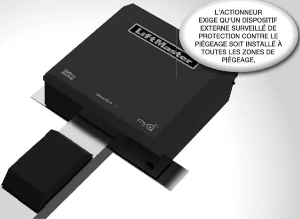
text_image
L'ACTIONNEUR EXIGE QU'UN DISPOSITIF EXTERNE SURVEILLÉ DE PROTECTION CONTRE LE PIÉGEAGE SOIT INSTALLÉ À TOUTES LES ZONES DE PIÉGEAGE.natural_image
Illustration of a two-story house with trees and a curved roof, no visible text or symbols
natural_image
3D architectural rendering of a modern building with windows and a curved road (no text or symbols visible)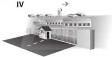
natural_image
Illustration of a school building with an airplane flying overhead and road markings (no text or symbols)natural_image
3D rendering of a mechanical housing or enclosure with mounting holes and internal components (no text or symbols visible)Rail de 2,4 m (8 pi) HCT08
Rail de 3,1 m (10 pi) HCT10
Rail de 3,7 m (12 pi) HCT12
Rail de 4,3 m (14 pi) HCT14
Rail de 4,9 m (16 pi) HCT16
WARNING
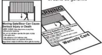
text_image
Moving Gate/Door Can Cause Serious Injury or Death EXP-COMA: 100% of the road To prevent death. For actual operation, the patient is trying to the following: for serious cases In addition, you can't support someone to avoid a risk of death. WARNING Warranty CardBatterie 12 V c. c. 7 AH (2)
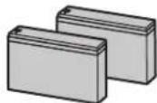
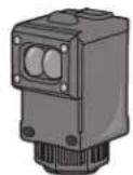
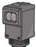
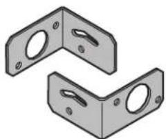
natural_image
Two identical L-shaped metal bracket components with mounting holes (no text or symbols)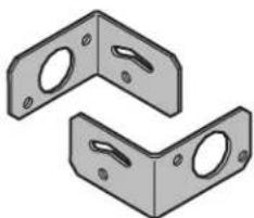
natural_image
Two identical L-shaped metal bracket components with mounting holes (no text or symbols)Step 1 Connect Rail to Operator
- Remove the screws and open the cover of the operator.
- Remove the chain guard from the chassis.
- Lay the rail on the floor. Align the key holes on the end of the rail with the cap screws on the chassis.
- Attach the rail to the chassis with the carriage bolts, lock nuts, and washers provided. Tighten cap screws on key holes.
- Cut the cable tie on the chain and position the trolley within 3 feet (.9 m) of the end of the rail.
- Wrap the chain around the sprocket.
- Adjust the chain tension with the turnbuckle so that the chain hangs no more than 1/4" (.64 cm) from the top of the rail. Tighten the hex nut to secure the chain.
- Reattach the chain guard to the chassis.
- Close the cover and attach with screws.
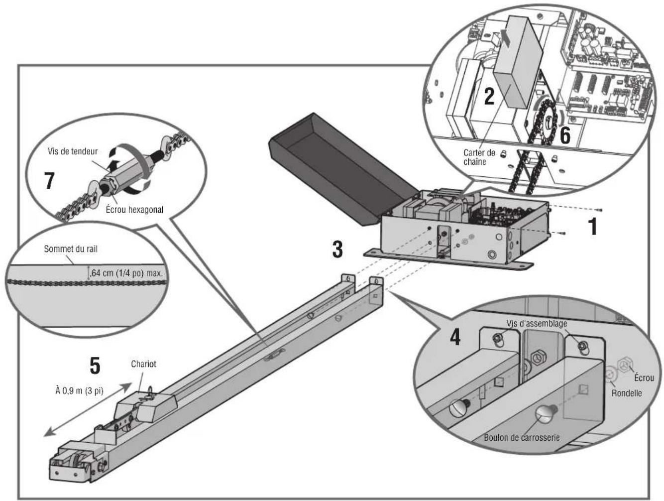
Step 2 Install Vented Plug
- Remove the dome plug from the operator chassis.
- Remove the solid plug in the gear reducer and replace vented plug (provided in bag with manual).
- Tighten the vented plug with a socket or Allen wrench.
- Re-insert the dome plug.
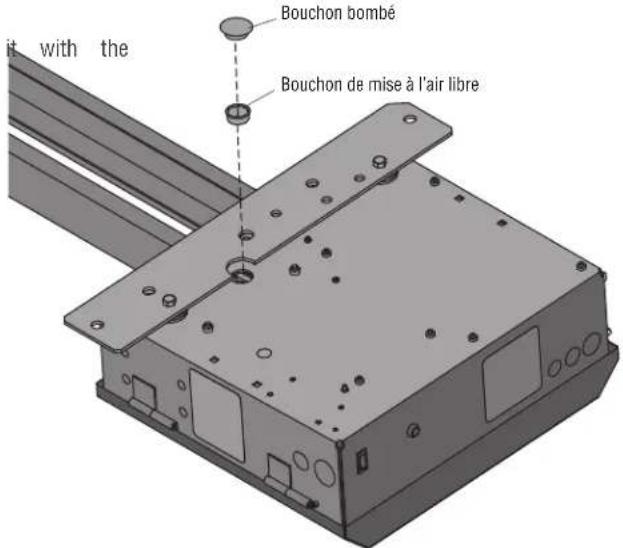
natural_image
Illustration of a person climbing a ladder inside a metal fence (no text or symbols)natural_image
Illustration of a person on a ladder installing or adjusting a wall-mounted device (no text or symbols visible)plafond.
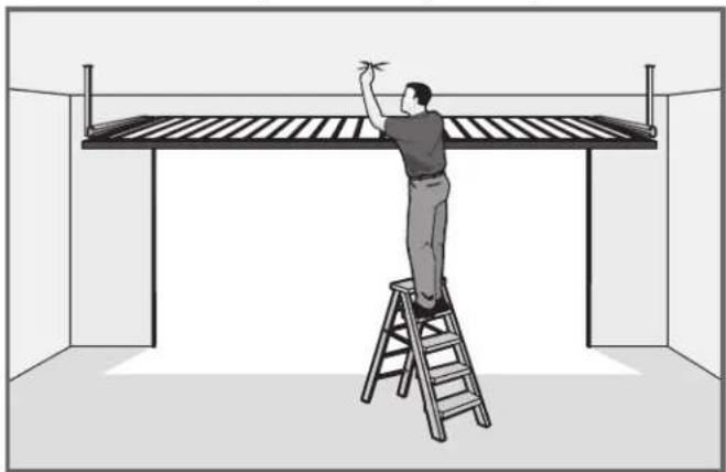
natural_image
Illustration of a person on a ladder installing or adjusting a large metal frame structure (no text or symbols present)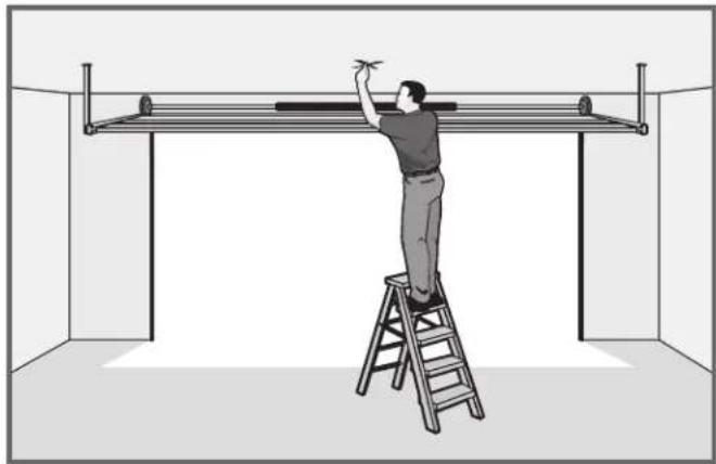
natural_image
Illustration of a person on a ladder installing or adjusting a metal frame inside a room (no text or symbols)INSTALLATION
Step 4 Mount the Operator
- Place the motor unit on packing material to protect the cover. Make sure the header bracket is in the center of the opening. Bolt or weld the header bracket to the wall.
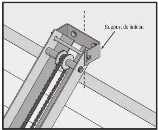
text_image
Support de linteau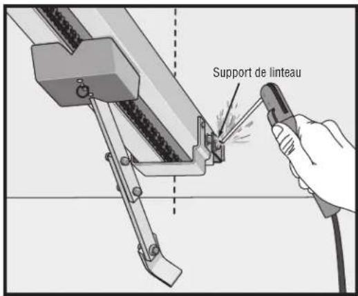
text_image
Support de linteau- Lift the operator and align with center mark on ceiling. Have someone hold the operator in place or use a post as a temporary support. Bolt the operator to the ceiling. (A support post is not part of the operator. Use only for installation.) NOTE: The HCT14 and HCT16 rails have an additional mounting hole in the middle of the rail for installing an additional support bracket (not included).
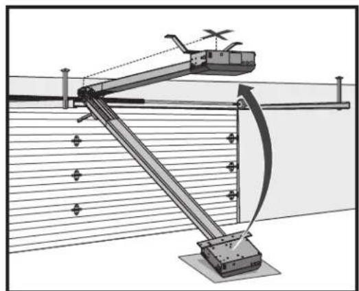
natural_image
Technical diagram of a mechanical linkage system with no visible text or symbols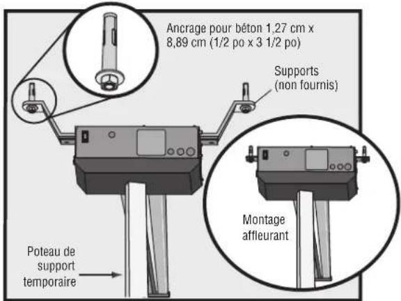
- Bolt or weld arm to gate/door.
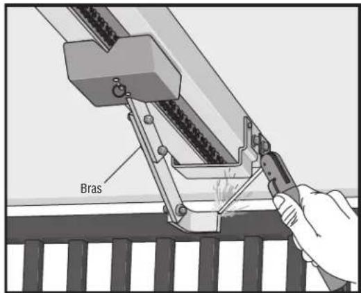
text_image
Bras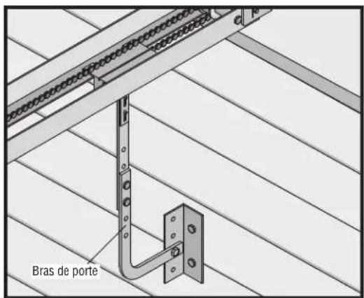
text_image
Bras de porteINSTALLATION
AVERTISSEMENT
text_image
1 SET OPEN SET CLOSE 2 MOVE GATE 3 SET OPEN SET CLOSE 4 PRESS & RELEASE TO BEGIN LIMIT SETUP 5 SET OPEN SET CLOSE 6RÉGLAGES
text_image
TEST BUTTONS AVR SAL E NAD CONE BOS FLOW2
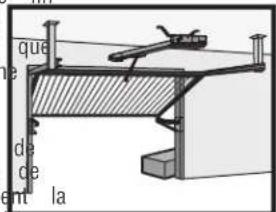
text_image
que de ce ent la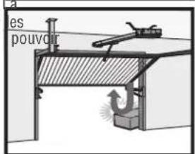
text_image
es pouvoir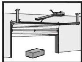
natural_image
Simple line drawing of a wooden bench with a lever and a brick base (no text or symbols)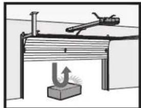
natural_image
Simple line drawing of a mechanical setup with a lever and base, no text or symbols presenttext_image
SET OPEN SET CLOSE OPEN CLOSE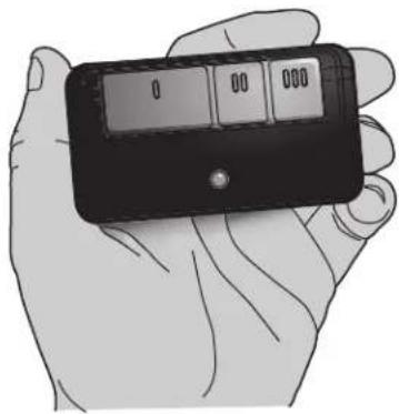
natural_image
Illustration of a hand holding a black handheld device with a digital display (no text or symbols visible)FONCTIONNEMENT
natural_image
Diagram of a mechanical joint or bracket assembly with radiating forces and no visible text or symbolsD
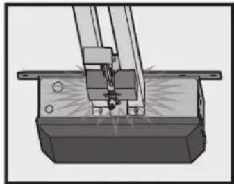
natural_image
Mechanical assembly diagram showing a cutting tool interacting with a base block (no text or symbols visible)Adjustable Open Speed
The HCTDCU provides a high speed open option to help flow in high traffic areas. Select the open speed using the BIPART DELAY switch.
BIPART DELAY OFF (default) = 8 in./sec. open speed BIPART DELAY ON (fast) = 11 in./sec. open speed
NOTE: After changing the open speed, the force will need to be account for the change of power used, see Limit and Force Ad section.
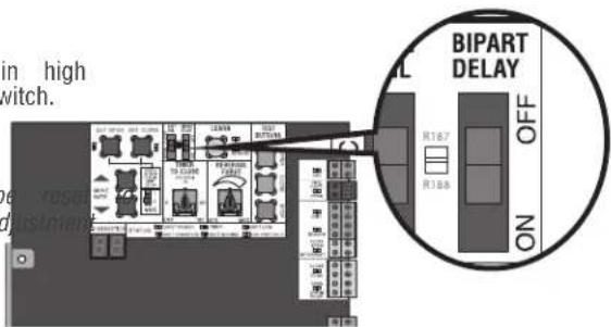
text_image
in high switch. BIPART DELAY OFF ON 1:67 1:345Télécommande
natural_image
Hand turning a button into a mechanical component with rotating arrows (no text or symbols visible)Étape 2
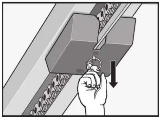
natural_image
Illustration of a hand using a tool to press or install a mechanical component, with no visible text or symbols.Étape 3
natural_image
Diagram of a person using a lift-mounted lever system to lift a metal structure (no text or symbols present)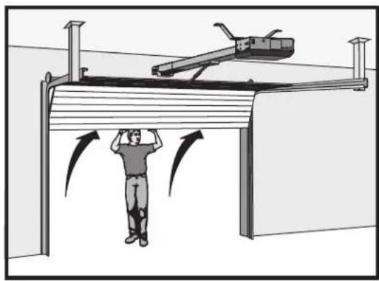
natural_image
Illustration of a person standing under a structure with directional arrows indicating motion or force (no text or symbols present)INTERRUPT (INTERRUPTION) (2 bornes)
text_image
negative la c KUT c RAN ON ON ON ON ON ON ON ON ON ON ON ON ON ON ON ON ON ON ON ON ON ON ON ON ON ON ON ON ON ON ON ON ON ON ON ON ON ON ON ON ON ON ON ON ON ON ON ON ON ON On Anti TAR. NO COM INC. NO COM INC. OPEN CLOSE SRC. OPN. CL8. STT. C71ROUGE
COM
VERT
RGL24LY
feu rouge/vert
natural_image
Illustration of various electrical connectors and components (no text or symbols)natural_image
Black rectangular electronic device with a logo on top (no visible text or symbols)Passerelle internet LiftMaster
text_image
a fournit aircite