FSHSR09A1A - Air Conditioning Friedrich - Free user manual and instructions
Find the device manual for free FSHSR09A1A Friedrich in PDF.

| Product type | Split air conditioner |
| Brand | Friedrich |
| Model | FSHSR09A1A |
| Cooling capacity | 9000 BTU/h |
| Heating capacity | 9000 BTU/h (heat pump) |
| Power supply | 220-240 V ~ 50 Hz |
| Recommended breaker | 15 A |
| Refrigerant | R410A |
| Main functions | Auto, Cool, Heat, Dry, Fan, Turbo, Sleep, Timer ON/OFF, Air Sweep |
| Remote control | Included (AAA 1.5V batteries not included) |
| Filter | Washable, clean every 3 months |
| Outdoor temperature range (cooling) | -15°C to 48°C |
| Outdoor temperature range (heating) | -20°C to 24°C |
| Common error codes | H1 (defrost), E5 (unstable voltage), etc. |
| Safety | Mandatory grounding, differential circuit breaker, automatic shutdown |
| Maintenance | Filter cleaning, annual check by professional |
| Warranty | Consult your dealer |
| Indoor unit weight (estimated) | Approx. 10 kg |
| Outdoor unit weight (estimated) | Approx. 25 kg |
Frequently Asked Questions - FSHSR09A1A Friedrich
User questions about FSHSR09A1A Friedrich
0 question about this device. Answer the ones you know or ask your own.
Ask a new question about this device
Download the instructions for your Air Conditioning in PDF format for free! Find your manual FSHSR09A1A - Friedrich and take your electronic device back in hand. On this page are published all the documents necessary for the use of your device. FSHSR09A1A by Friedrich.
USER MANUAL FSHSR09A1A Friedrich
- Do not connect air conditioner to multi-purpose socket. Otherwise, it may cause fire hazard
- Disconnect power supply when cleaning air conditioner. Otherwise, it may cause electric shock.
- Do not spray water on indoor unit. It may cause electric shock or malfunction.
- Do not spill or submerge remote controller in liquids, remote may malfunction or no longer operate.
- Do not repair air conditioner by yourself. It may cause electric shock or damage. Please contact dealer when you need to repair air conditioner.
- Do not block air outlet or air inlet. It may cause malfunction.
- If you need to relocation of air conditioner is required please contact licensed authorize service or contact dealer for more information. Otherwise personal injury or damage can occur.
- Do not step on top panel of outdoor unit, or put heavy objects. It may cause damage or personal injury.
- Do not extend fingers or objects into air inlet or air outlet. It may cause personal injury or damage.
- Air Conditioner should be properly grounded. Incorrect grounding may cause electricshock.
- Do install the disconnect. If not, it may cause malfunction.
- Installation and maintenance must be performed by qualified professionals. Otherwise, it may cause personal injury or damage.
Working temperature range
| MM18YJ | Indoor side DB/WB(°F/°C) | Outdoor side DB/WB(°F/°C) |
| Maximum cooling 89 | 6/73.4(32/23) 109.4/78.8(43/26) | |
| Maximum heating 80 | 6/-(27/-) 75.2/64.4(24/18) | |
The operating temperature range (outdoor temperature) for cooling only unit is 5^(-15^) 118^(48^) ; for heat pump unit is -4^(-20^) 75^(24^)
| MM24YJ | Indoor side DB/WB(°F/°C) | Outdoor side DB/WB(°F/°C) |
| Maximum cooling 89 | 6/73.4(32/23) 115/78.8(46/26) | |
| Maximum heating 80 | 6/-(27/-) 75.2/64.4(24/18) |
The operating temperature range (outdoor temperature) for cooling only unit is 5^(-15^) 115^(46^) ; for heat pump unit is 19^(-7^) 75^(24^)
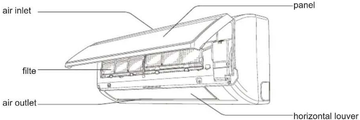
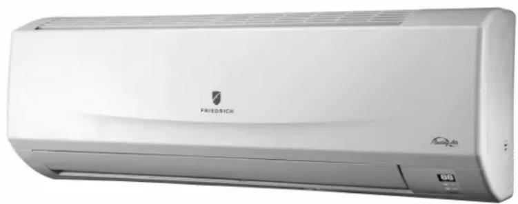
Parts name
Indoor Unit
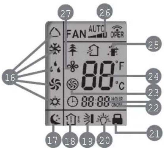
display

temp. indicator
cooling indicator


-drying indicator
heating indicator

(b) power indicator
aux.button
receiver window
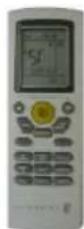
remote control
Outdoor Unit
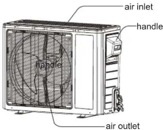

Notice:
Actual product may be different from above graphics, please refer to actual products.

Operation of Remote Controller
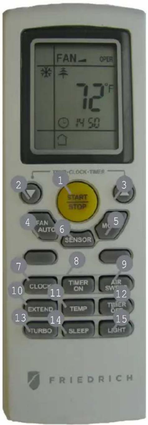
1 START/STOP
Press to start or stop operation.
2: Press to decrease temperature setting.
3 Press to increase temperature setting.
4 FANAUTO
Press to set fan speed.
MODE
Press to select operation mode (AUTO/COOL/DRY/FAN/HEAT).
6 SENSOR
7 CLOCK
Press to set clock.
8 TIMER ON
Press it to set auto-on timer.
9 AIR SWEEP
Press it set swing angle.
10 EXTEND
11 TEMP
12 TIMER OFF
Press to set auto-off timer
13 TURBO
14 SLEEP
15 LIGHT
Press to turn on/off the light.

Operation of Remote Controller
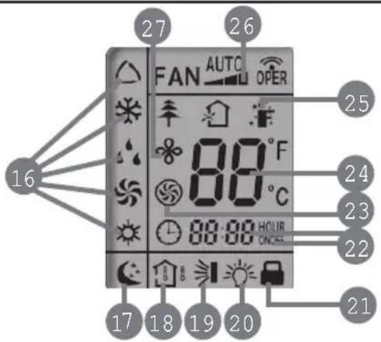
16 MODE icon:
If MODE button is pressed, current operation mode icon (AUTO), COOL)
(DRY), (FAN) or (HEAT only for heat pump models) will show.
17 SLEEP icon :
is displayed by pressing the SLEEP button. Press this button again to clear the display.
18 TEMP icon:
Pressing TEMP button, (set temperature), (indoor ambient temperature) (outdoor ambient temperature) and blank is displayed circularly.
AIR SWEEP icon:
is displayed when pressing the AIR SWEEP button.
Press this button again to clear the display.
20 LIGHT icon:
is displayed by pressing the LIGHT button. Press LIGHT button again to clear the display.
21 LOCK icon:
is displayed by pressing "+" and "-" buttons simultaneously. Press them again to clear the display.
22 SET TIME display:
After pressing TIMER button, ON or OFF will blink. This area will show the set time.
23 TURBO icon:
is displayed when pressing the
again to clear the display.
24 DIGITAL display:
This area will show the set temperature.

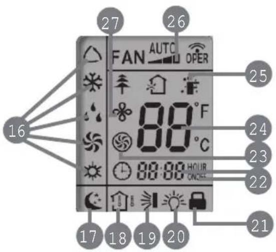
25 SENSOR icon:
is displayed when pressing the SENSOR button. Press this button again to clear the display.
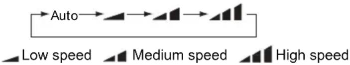
26 FAN SPEED display:
Press FAN button to select the desired fan speed setting (AUTO-Low-Med-High).Your selection will be displayed in the LCD windows, except the AUTO fan speed.
27EXTENDicon:
is displayed when pressing the EXTEND button. Press this button again to clear the display.

Remote Control Instructions
Remote Controller Description
1 START/STOP:
Press this button to turn on the unit. Press this button again to turn off the unit.
2▼:
Press this button to decrease set temperature. Hold it down for 2 seconds or more to rapidly decrease set temperature. In AUTO mode, set temperature is not adjustable.
3
Press this button to increase set temperature. Hold it down for 2 seconds or more to rapidly increase set temperature. In AUTO mode, set temperature is not adjustable.
4 FAN AUTO:
This button is used for setting Fan Speed in the sequence that goes from AUTO,
to, then back to Auto.
MODE:
Each time you press this button, a mode is selected in a sequence that goes from AUTO, COOL, DRY, FAN, and HEAT *, as the following:
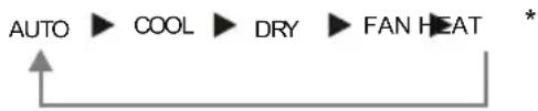
*Note: Only for models with heatingfunction.
After energization, AUTO mode is defaulted. In AUTO mode, the set temperature will not be displayed on the LCD, and the unit will automatically select the suitable operation mode in accordance with the room temperature to make indoor room comfortable.
6 SENSOR(SAVE):
Press this button to turn on SENSOR(SAVE) function. Saves room ambient temperature and automatically adjusts maintaining that room ambient until pressed again which cancels the SENSOR(SAVE) function.
7 CLOCK:
Pressing CLOCK button, blinks. Within 5 seconds, pressing + or - button adjusts the present time. Holding down either button above 2 seconds increases or decreases the time by 1 minute every 0.5 second and then by 10 minutes every 0.5 second. During blinking after setting, press CLOCK button again to confirm the setting, and then will be constantly displayed.

Remote Control Instructions
8 TIMER ON:
Press this button to initiate the auto-ON timer. To cancel the auto-timer program, simply press this button again.
After pressing this button, disappears and "ON "blinks. 00:00 is displayed for ON time setting. Within 5 seconds, press + or - button to adjust the time value. Every press of either button changes the time setting by 1 minute. Holding down either button rapidly changes the time setting by 1 minute and then 10 minutes. Within 5 seconds after setting, press TIMER ON button to confirm.
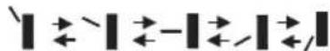
9 AIR SWEEP:
Press this button to set up & down swing angle, which circularly changes as below:
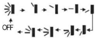
This remote controller is universal. If any command ≥slant 1 , ≥slant 1 or ≥slant 1 is sent out, the unit will carry out the command as ≥slant 1
indicates the guide louver swings as:
10 EXTEND(DRY):
Pressing Extern Cool or Dry mode, the icon is displayed and the indoor fan will continue operation for 10 minutes in order to dry the indoor unit even though you have turned off the unit.
After energization,EXTEND OFF is defaulted.EXTENDED available in AUTO, FAN or HEAT mode.
11 TEMP:
By pressing this button you can display the indoor setting temperature or indoor ambient temperature. When the indoor unit is still operating, setting temperature,
if the temperature's display status is changed from other status to ",displays the ambient temperature, 5s later or within 5s, it receives other remote control signal that will return to display the setting temperature. if the users haven't set up the temperature displaying status,that will display the setting temperature.(This function is not applicable for some models).
12 TIMER OFF :
Press this button to initiate the auto-off timer. To cancel the auto-timer program, simply press the button again. TIMER OFF setting is the same as TIMER ON.
13 TURBO:
Press this button to activate / deactivate the Turbo function which enables the unit to reach the preset temperature in the shortest time. In COOL mode, the unit will blow strong cooling air at super high fan speed. In HEAT mode, the unit will blow strong heating air at super high fan speed. (This function is not applicable for some models).

Remote Control Instructions
14 SLEEP:
Press this button to go into the SLEEP operation mode. Press it again to cancel this function. This function is available in COOL or DRY mode to maintain the most comfortable temperature for you.
15 LIGHT:
Press LIGHT button to turn on the display's light and press this button again to turn off the display's light. If the light is turned on, 是 is displayed. If the light is tunned off, disappears.
16 Combination of "+" and "-" buttons: About lock
Press "+" and "-" buttons simultaneously to lock or unlock the keypad. If the remote controller is locked, is dispasaryd mytissute, blinks three times.
Combination of "MODE" and "-" buttons: Allows you to toggle between Fahrenheit and Celsius. When the unit is OFF, press "MODE"and "-" buttons simultaneously to switch between ^ C and ^ F
Replacement of Batteries
1.Remove the battery cover plate from the rear of the remote controller. (As shown in the figure)
2. Take out the old batteries.
3.Insert two new AAA1.5V dry batteries, and pay attention to the polarity (+/-) .
4. Reinstall the battery cover plate
\* Notes:
- When replacing the batteries, do not use old or different types of batteries, it may cause malfunction.
- If the remote controller will not be used for a long time, please remove batteries to prevent batteries from leaking.
Remote should be kept 3 feet away from the TV set or stereos. - If the remote controller does not operate normally, remove batteries and reinsert after 30 seconds. If abnormal operation continues, replace the batteries.
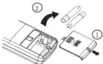
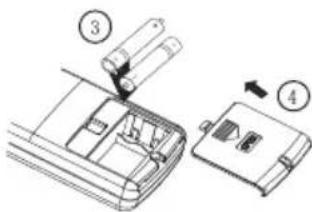
Diagram for removal of batteries
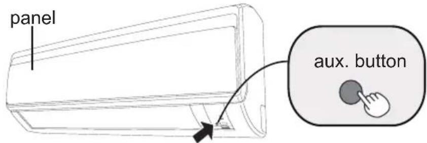
Emergency operation
If remote controller is lost or damaged, please use auxiliary button to turn on or turn off the air conditioner. The operation in details are as below: As shown in the fig. press aux. button to turn on or turn off the air conditioner. When the air conditioner is turned on, it will operate under auto mode.
Clean and maintenance
Note:
- Turn off the air conditioner and disconnect the power before cleaning the air conditioner to avoid electric shock.
- Do not wash the air conditioner with water to avoid electric shock.
- Do not use volatile liquid to clean the air conditioner.
Clean surface of indoor unit
When the surface of indoor unit is dirty, it is recommended to use a soft dry cloth or wet cloth to wipe it.
Note:
- Do not remove the panel when cleaning it.
Clean and maintenance
Clean filter

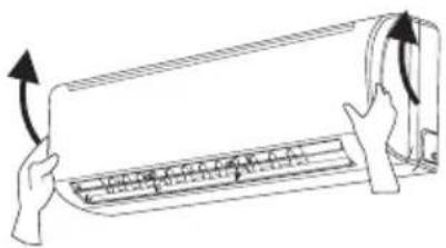
Open panel
Open panel to access filter.
2
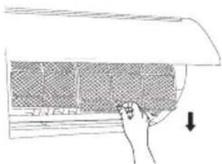
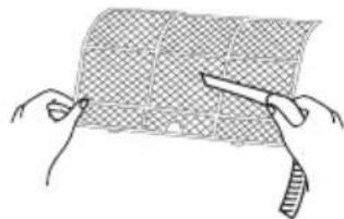
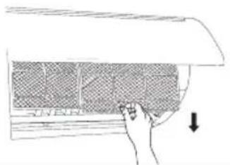
Remove filter
Remove the filter as indicated in the fig.
3
Clean filter
- Use vacuum or water to clean the filter.
- When the filter is very dirty, use warm water (below 113^ ) to clean it, and then allow to dry.
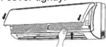
4
Install filter
Install the filter and then close the panel cover tightly.
Note:
The filter should be cleaned every three months. If environment is excessively dusty more frequent cleaning may be required.
■ After removing the filte, do not touch fins to avoid injur.
Air dry the filter to avoid deformation or fire hazard.
Clean and maintenance
Pre-season check up
- Check whether air inlets and air outlets are blocked.
- Check whether circuit breaker is in good condition.
- Check whether filter is clean
- Check whether mounting bracket for outdoor unit is damaged or corroded. If yes, please contact dealer.
- Check whether drainage pipe is damaged.
Off-season check up
- Disconnect power supply.
- Clean filter and indoor unit s panel.
- Check whether mounting bracket for outdoor unit is damaged or corroded. If yes, please contact dealer.
Notice for disposal of equipment
- Much of packaging is recyclable, check local city/county services for rules
- If disposal of air conditioner is required, please contact local dealer or consult service center for the correct disposal method.
Trouble Shooting
Prior to calling for service please review troubleshooting section to eliminate any issues.
| Issue | Check items Solution | |
| Indoor unit not working with remote. Or remote has no display. | ·Check batteries | ·Replace if needed. |
| ·Ensure remote is within operating distance. | ·Receiving range for signal is 26ft/8m. | |
| ·Are there obstacles? | ·Remove obstacles. | |
| ·Ensure remote is pointing directly at "receiving window" | ·Select proper angle and point the remote controller at the receiving window on indoor unit. | |
| ·If no display on remote or display is blurred. | ·Check and replace batteries. | |
| ·No display when operating remote controller? | ·Check check for damage to remote. If damaged please contact dealer for replacement. | |
| ·Has remote come into contact with liquid or been submerged in liquid? | ·If so please discontinue use and contact dealer for replacement. | |
| No air coming from unit | ·Is Air inlet or outlet restricted? | ·Remove restrictions. |
| ·If in heating mode has set point been reached? | ·After reaching the set temperature, indoor fan will stop blowing. | |
| ·Did Heat mode just come on? | Equipment has "Hot start" feature allowing the unit outdoor to start first so cold air is not blown into space. |
Trouble Shooting
| Issue | Check items Solution | |
| Air conditioner not operating | ·Has there been a power failure? | ·Wait for power to be restored. |
| ·Are there lights on the display? | ·If no check circuit breaker. | |
| ·Circuit breaker tripping? | ·Call servicer or dealer for licensed professional. | |
| ·Wires not attached? | ·Call for immediate service. | |
| ·Unit will not restart after turning off? | ·Wait for 3min, then attempt to turn on unit. If unit doesn't restart please call service. | |
| ·Is remote functioning properly? | ·If no- See remote troubleshooting | |
| Mist/Fog coming from indoor unit discharge louvers | ·Check indoor temperature and humidity. | ·Allow unit to run for sometime Mist/fog should stop once normal Indoor conditions stabilize. |
| Cannot adjust set temperature | ·Unit operating under Auto mode. | ·Temperature can't be adjusted while in Auto mode. Please change operation modes if needing to change set point. |
| ·Your required temperature exceeds the set temperature range. | ·Set temperature range: 61°F-86°F. | |
| Cooling temperature and Heating temperature not sufficient | ·Brownout conditions occurred? Voltage too low. | ·Wait until power stabilizes. |
| ·Is filter dirty? | ·Clean the filter. | |
| ·Set temperature is in proper range? | ·Adjust temperature to proper range. | |
| ·Door and window are open? | Close door and window. ·Allow time for system to stabilize. |
Service and Assistance
| Issue | Check items Solution | |
| Odors comming from system | ·Check for source of odor. | ·Eliminate the odor and clean filter. |
| Air conditioner operates abnormally | ·Check for inclimate weather or excessive wireless signals. | ·Power unit down for 3 minutes and try operation again. |
| Outdoor unit has mist/fog | ·Is system operating in heating? | ·While in defrost unit may discharge mist/fog until clear of moisture. |
| Noise like there is water inside unit | ·Did air conditioner just come on? | ·Noise is the sound of refrigerant flowing inside the system. Once stabilized noise will discontinue. |
| Crackling sound | ·Did air conditioner just come on? | ·Temprature difference between plastic front and discharge temp. may be great once temperature stabilizes noise will discontinue. |
Before calling for service, please check the "Basic troubleshooting" section above. This may help you to find the answer to your problem, avoid unnecessary service calls, and save the cost of a service call if the problem is not due to the product itself. If you have checked the "Basic troubleshooting" section and still need help, below you will find a list of available services:
1 You can find the name of your local Authorized Service Provider by visiting our website at www.friedrich.com.
2 If you require further assistance please call Friedrich customer support at 1-800-541-6645.
3 Before calling please make sure that you have the full model and serial number, as well as the date of purchase of you equipment available. Providing us with this information will allow us to better assist you.
Trouble Shooting
Error Code
- When air conditioner status is abnormal, temperature indicator on indoor unit will blink to display corresponding error code. Please refer to below list for identification of error code.
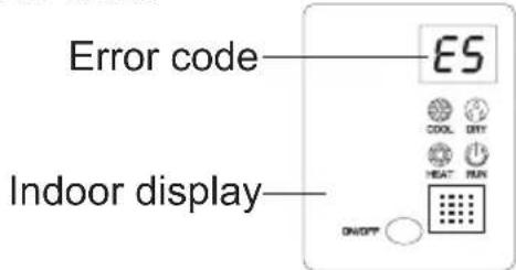
Above indicator diagram is only for reference. Please refer to actual product for the actual indicator and position.
| Error code | Troubleshooting |
| H1 | Unit is in defrost mode - This is normal. |
| E5 | Supply voltage was unstable during operation. Please restart, if restart doesn't work, contact dealer or qualified service. |
| H4 | System noticed abnormal temperature range. Please restart, if restart doesn't work, contact dealer or qualified service. |
| U8 | Indoor component has error. Please restart, if restart doesn't work, contact dealer or qualified service. |
| H6 | Indoor component has error. Please restart, if restart doesn't work, contact dealer or qualified service. |
| C5 | Please contact qualified servicer or dealer. |
| F1 | Please contact qualified servicer or dealer. |
| F2 | Please contact qualified servicer or dealer. |
Note: If there're other error codes, please contact qualified professionals for
Warning
If any of the below occur, please disconnect power and contact qualified servicer immediately.
- Power cord has overheating or damaged.
- Unit operates loudly or abnormally during operation.
- Circuit breaker trips off frequently.
Air conditioner gives off burning smell.
- Indoor unit is leaking water.
- Do not repair or refit the air conditioner by yourself
If the air conditioner operates under abnormal conditions, it may cause malfunction, electric shock or fire hazard
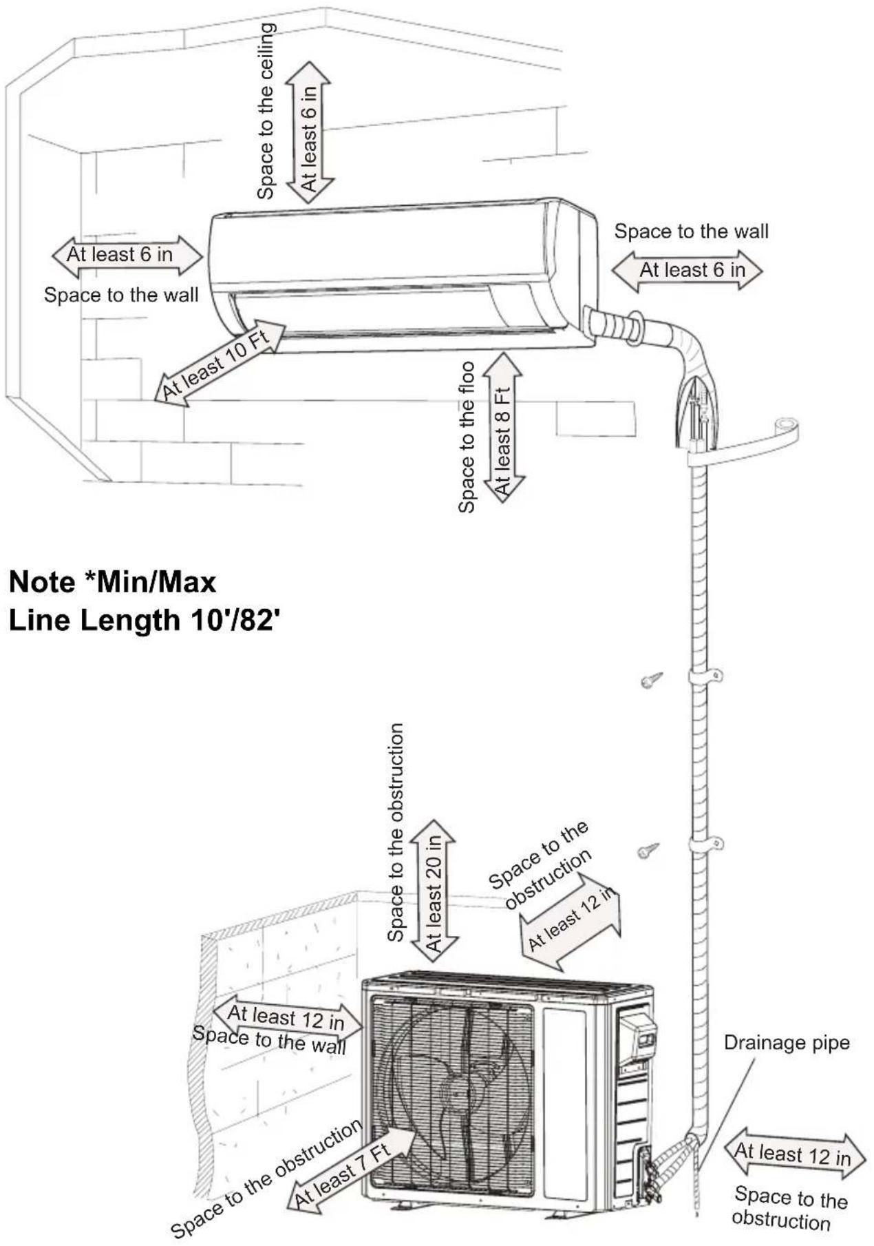
Installation dimension diagram
Tools for installation
| 1. Level | 2. Screw driver | 3. Impact drill |
| 4. Drill head | 5. Pipe expander | 6. Torque wrench |
| 7. Open-end wrench | 8. Pipe cutter | 9. Leakage detector |
| 10. Vacuum pump | 11. Manifold gauges | 12. Multimeter |
| 13. Allen/spANNER wrenches 14. Measuring tape | ||
Note:
- Please contact a local qualified installer for installation.
- Ensure power cords are rated for use with equipment.
Selection of installation location
| Basic requirement | Indoor unit |
| Installing the unit in the following locations may cause operational issues with equipment. If unavoidable seek assistance from local dealer.1.Any location with an excessive heat source, where flammable, gasses or volatile flyings exist.2.Any location with high-frequency devices (such as welding machine, medical equipment).3.Coastal locations.4.Corrosive or spaces that are excessively wet, such as pool rooms, laundry and bath rooms. | 1. There should be no obstruction near air inlet and air outlet.2. Location should have acceptable condensate disposal considerations.3. Select a location which is out of reach for children.4. Installed location should be rated for the weight of equipment and not create vibration or noise.5. The appliance must be installed 8 Ft above floor.6. Do not install directly above heat source or electrical appliance. |
| Outdoor unit | |
| 1. Be considerate of installed location due to hot airflow from unit and any noise that it may create.2. Location should be well ventilated and dry, outdoor unit not to be exposed directly to sunlight or strong wind.3. The location should be able to withstand the weight of outdoor unit.4. Ensure installation conforms to installation diagram.5. Select a location which is out of reach for children and far away from animals or plants. If it is unavoidable, please add the fence for purpose of safety. | |
Requirements for electric connection
Safety precaution
- Must follow national and regional safety regulations when installing the unit.
- According to the local safety regulations, use qualified power supply circuit an circuit breaker.
- Make sure the power supply matches with the requirement of air conditioner. Install proper power supply cables before using the air conditioner.
- Properly connect all wires.
- Be sure to cut off the power supply before proceeding any work related to electricity and safety.
- Do not apply voltage until installation is complete.
- The temperature of refrigerant circuit will be high, please keep communication cable clear of copper tubes.
Grounding requirement
- Qualified installer must ensure proper grounding of air conditioner.
- The yellow-green wire in air conditioner is the grounding wire. Do not use for any other purpose.
- Grounding should follow national and local electrical regulations.
- Air conditioner should be installed so that servicer can access electrical connections.
- Local code approved disconnect box must be used.
- Including an circuit break with suitable capacity, please note the following table. Switch should include magnet break and heat break function, this will assist with protection of circuit.
| Models | Circuit breaker |
| 18/24K | 25A |
Installation of indoor unit
Step one: choosing installation location
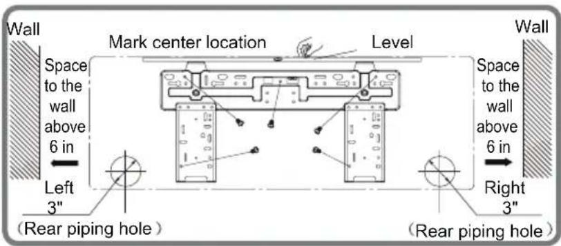
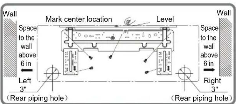
Step two: install wall bracket
- Hang wall bracket, install center screw and apply level.
- If required pre-drill in the locations you've chosen for mounting, install required mounting hardware and secure to wall.
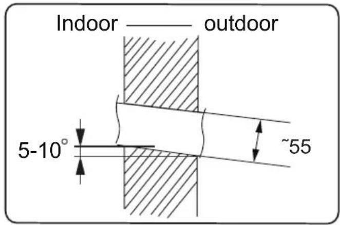
Step three: open piping hole
- Choose the position of piping hole according to the direction of outlet pipe. The position of piping hole should be a little lower than the wall-mounted frame, shown as below.
18K
24K
- Drill hole through wall with a diameter of 3'' on the selected location. In order to drain smoothly, slant the hole on the wall slightly downward to the outdoor side with the gradient of 5 - 10^ .
Installation of indoor unit
Note:
- Wall penetration collar is field supplied, ensure hole is properly insulated once unit is installed.
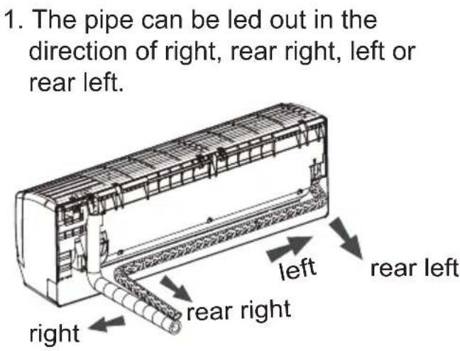
Step four: outlet pipe
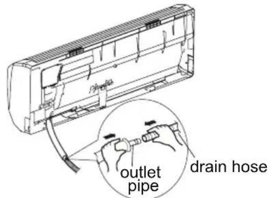
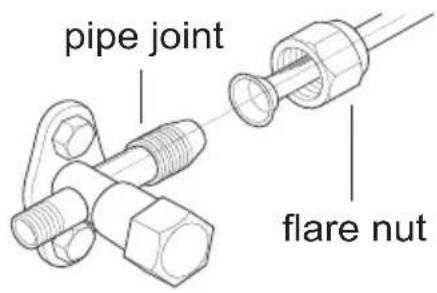
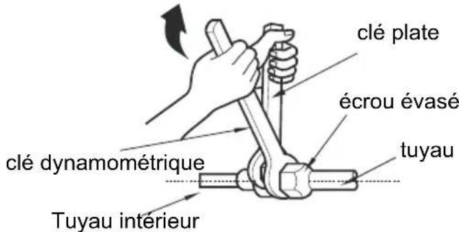
Step five: connect the pipe of indoor unit
- Connect the male pipe joint to the flare nut.
- Pretighten flare nut by hand.
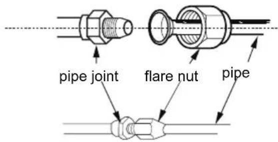
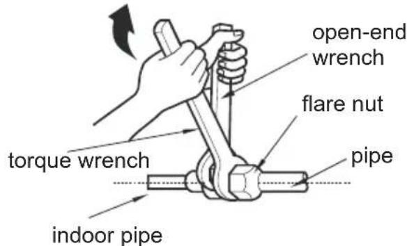
- Adjust the torque force by referring to the following sheet. Place the open-end wrench on the pipe joint and place the torque wrench on the flare nut. Tighten the flare nut with torque wrench.
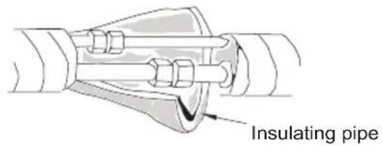
Installation of indoor unit
- Wrap with insulation then wrap with tape.
| Hex nut diameter | Tightening torque (N·m) |
| Φ 6 | 15~20 |
| Φ 9.52 | 30~40 |
| Φ 12 | 40~55 |
| Φ 16 | 60~65 |
| Φ 19 | 70~75 |
Step six: install drain hose
-
Connect the drain hose to the outlet pipe of indoor unit.
-
Bind the joint with hose clamp.
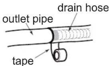
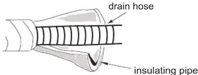
Note:
- Add insulation to pipe on the indoor drain hose in order to prevent condensation.
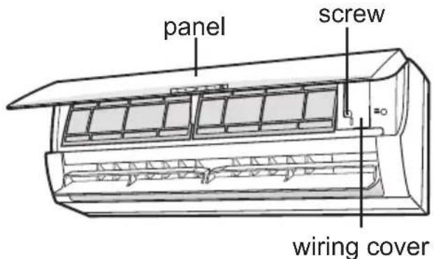
Step seven: connect power to indoor unit
- Open the panel, remove the screw on the wiring cover. Remove.
Installation of indoor unit
- Make the power connection wire go through the cable-cross hole at the back of indoor unit and then pull it out from the front side.
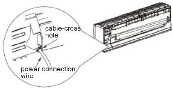
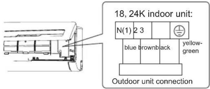
- Remove the wire clip; connect the power connection wire to the wiring terminal according to the color; tighten the screw and then fix the power connection wire with wire clip.
- Put wiring cover back and then tighten the screw.
- Close the panel.
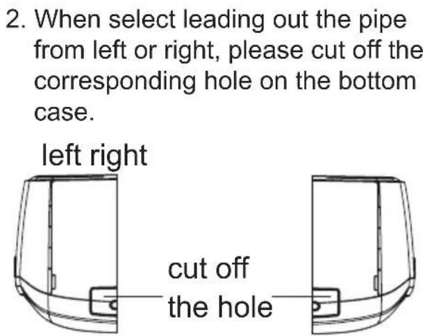
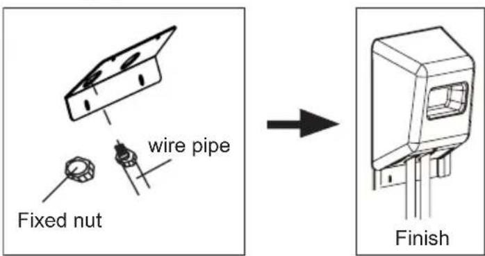
Notice before installation
- How to install the over line pipe(According to the direction as show.)
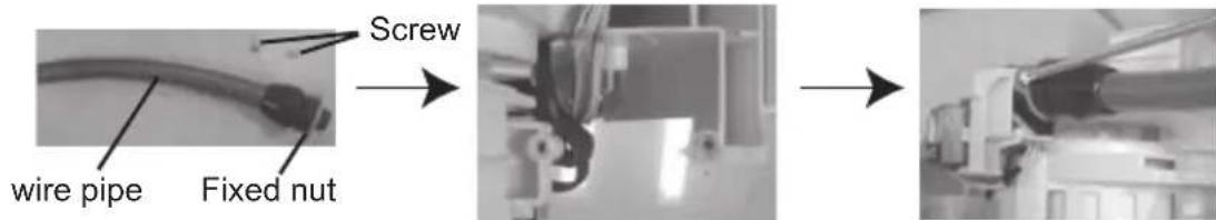
- Finish(According to the direction as show in right figure.
Note:
- All electrical connections must be completed by a qualified professional.
- If required by local code install circuit breaker inline. Must be 3-Pole.
Installation of indoor unit
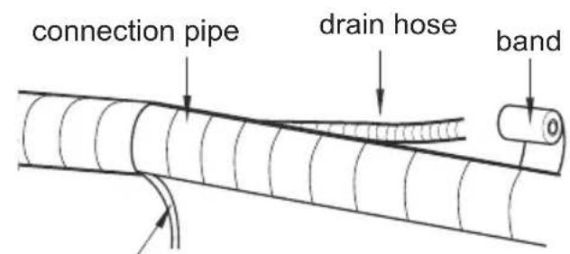
Step eight: bind up pipe
- Bind up the connection pipe, power cord and drain hose with the band.
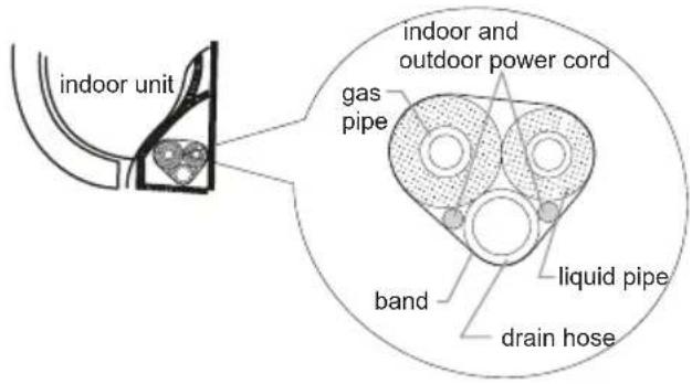
- Plan for bends in line set and ensure that cable and drain have extra length in those areas. Otherwise route these seperate from liquid and gas pipe.
indoor power cord
- Bind them evenly.
- The liquid pipe and gas pipe should be bound separately at the end.
Note:
- The power cord and control wire can't be crossed or winding.
- The drain hose should be bound at the bottom.
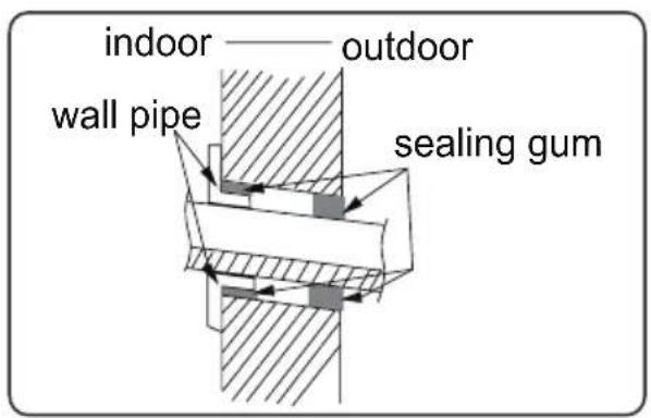
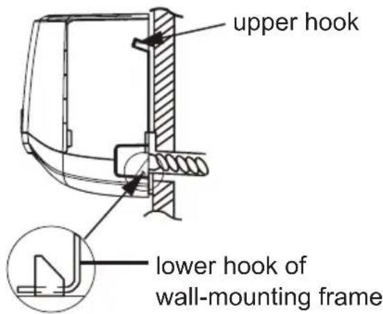
Step nine: hang the indoor unit
- Pass wrapped piping and drain/cable through hole in wall. (Ensure that drain is on on the bottom.)
- Hang the indoor unit on the wall-mounting frame.
- Stuff the gap between pipes and wall hole with insulation.
- Secure the wall pipe.
- Check if the indoor unit is installed firmly and closed to the wall
Note:
- Do not bend the drain hose excessively in order to prevent blocking.
Installation of outdoor unit
Step one: securing of outdoor unit (select location based on actual application)
- Select installation location to fit structure. Follow diagram and clearances.
- Secure the outdoor unit on the selected location with expansion screws or required hardware.
Note:
- Take sufficient protective measures when installing the outdoor unit.
Make sure the support can withstand at least four times of the unit weight. - The outdoor unit should be installed at least 1"in above the floor in order to install drain joint.
- For a unit with cooling capacity of 7800 17000 , 6 expansion screws are needed; for the unit with cooling capacity of 20500 27300 , 8 expansion screws are needed.
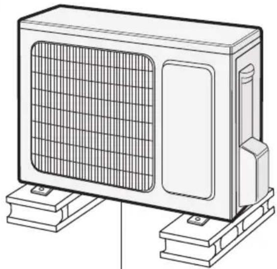
at least 1 in above the floor
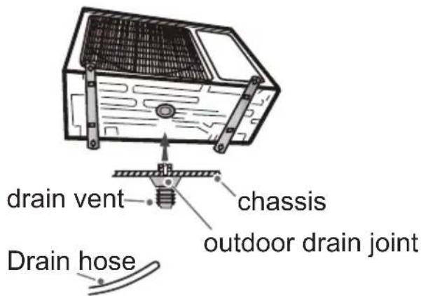
Step two: install drain joint (Only for cooling and heating unit)
- Connect the outdoor drain joint into the hole on the chassis, as shown in the picture below.
- Connect the drain hose into the drain vent.
Installation of outdoor unit
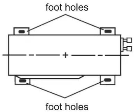
Step three: fix outdoor unit
- Place the outdoor unit on the support.
- Fix the foot holes of outdoor unit with bolts.
Step four: connect indoor and outdoor pipes
- Remove the screw on the right handle of outdoor unit and then remove the handle.
- Remove the screw cap of valve and attach the flare nut to the appropriate valve.
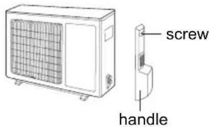
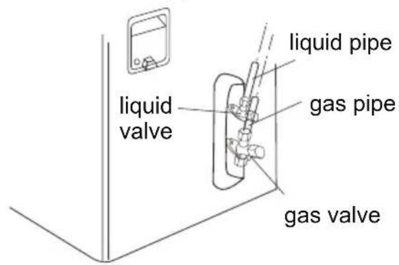
- Pretightening the flare nut by hand.
- Tighten the flare nut with torque wrench by referring to the sheet below.
| Hex nut diameter | Tightening torque (N·m) |
| Φ 6 | 15~20 |
| Φ 9.52 | 30~40 |
| Φ 12 | 40~55 |
| Φ 16 | 60~65 |
| Φ 19 | 70~75 |
Installation of outdoor unit
Step five: connect outdoor electric wire
- Remove the wire clip; connect the power connection wire and signal control wire (only for cooling and heating unit) to the wiring terminal according to the color; fix them with screws.
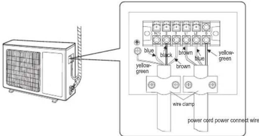
- Secure the power connection wire and signal control wire with wire clip (only for cooling and heating unit).
Note:
- After tighten the screw, pull the power cord slightly to check if it is firm
- Never cut the power connection wire to prolong or shorten the distance.
- The connecting wire and connection pipe cannot touch each other.
- Top cover of outdoor unit and electric box assembly should be fixed by the screw. Otherwise, it can cause a fire, or short circuit caused by water or dust
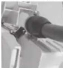
Install the over line pipe
Installation of outdoor unit
Step six: neaten the pipes
- The pipes should be placed along the wall, bent reasonably and hidden if possible. Min. radius of bend to the pipe is 4 in.
- If the outdoor unit is higher than the wall penetration, you must set a U-shaped curve in the pipe before pipe goes into the room, in order to prevent rain from getting into the room.
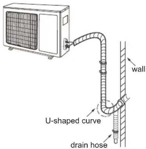
Note:
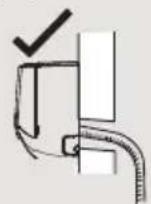
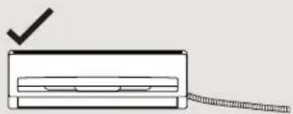
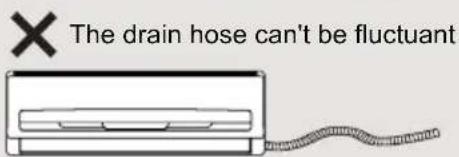
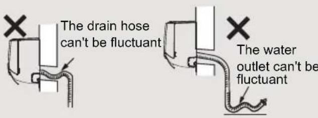
- The through-wal height of drain hose shouldn't be higher than the outlet pipe hole of indoor unit.
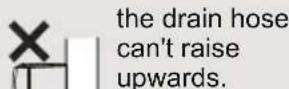
- The water outlet can't be placed in water in order to drain smoothly.
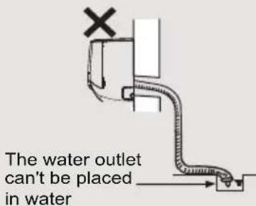
- Slant the drain hose slightly downwards. The drain hose can't be curved, raised and fluctuant, etc
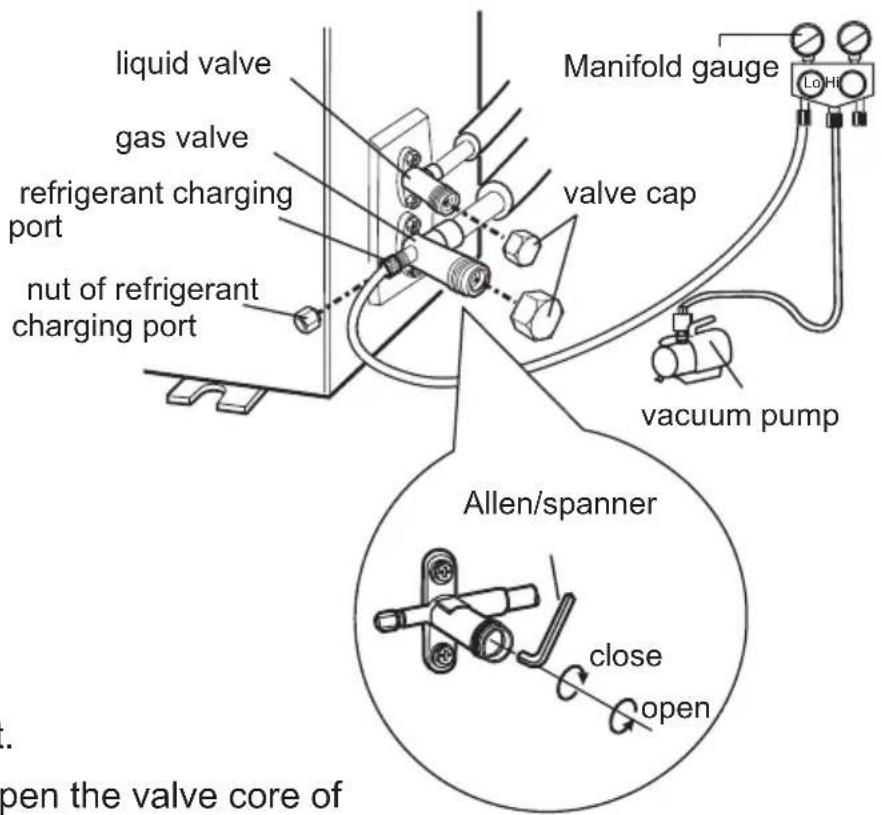
Pressure testing
Use Dry Nitrogen
- Remove the valve caps on the liquid valve and gas valve and the nut of refrigerant port
- Connect the charging hose of manifold to the refrigerant port, and the other to the nitrogen tank regulator.
- (System should hold 550 Psig for one hour.) Begin with
a. 150 psig for 5 min.
b. 300 psig for 15 min.
c. 550 psig for 1 hour.
- Test all connections with bubble solution.
- If no leaks are found proceed to vacuum steps below.
Vacuum pumping
Use vacuum pump
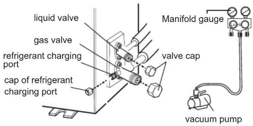
- Remove the valve caps on the liquid valve and gas valve and the nut of refrigerant port
- Connect the charging hose of manifold to the refrigerant port, and the other to the vacuum pump.
- Open manifold and allow vacuum to pump down for 20-30 min. Manifold should read -0.1MPa.
- Close vacuum pump and watch that the manifold remians at -0.1MPa. If pressure decreases then break vacuum and check for leaks with pressure test.
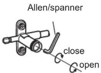
- Remove the piezometer, open the valve core of liquid valve and gas valve completely with inner hexagon spanner.
- Tighten the screw caps of valves and refrigerant charging vent.
- Reinstall the handle.
Check after installation
- Check according to the following requirement after finishing installation
| Items to be checked | Possible malfunction |
| Ensure unit has been installed correctly. | The unit may drop, shake or emit noise. |
| Has the system been leak tested? | System will may not cool or heat properly. |
| Has drain been properly insulated? | It may cause condensation and water dripping. |
| Is water draining well? | It may cause condensation and water dripping. |
| Is the voltage of power supply +/- 10% of the voltage marked on the nameplate? | It may cause system to operate improperly. |
| Is electric wiring and pipeline installed correctly? | May cause system to operate improperly |
| Is the unit grounded securely? | Electrical leakage could occur. |
| Are power connections properly sized? | System may not operate correctly. |
| Air inlet and Air outlets clear of restrictions? | System may not operate correctly. |
| All installation materials have been cleaned and removed? | It may cause malfunction or damaging the parts. |
| The gas valve and liquid valve of connection pipe are open completely? | System will may not cool or heat properly. |
Test operation
1. Preparation of test operation
- Customer approves of installation.
- Specify the important notes for air conditioner to the client.
2. Method of test operation
- Turn on power, press ON/OFF button on the remote controller to start operation.
- Press MODE button to select AUTO, COOL, DRY, FAN and HEAT to check whether the operation is normal or not.
- If the ambient temperature is lower than 61^ , the air conditioner can't start cooling.
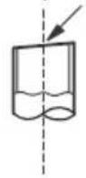
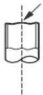
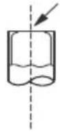
Pipe expanding method
Note:
Improper pipe expanding is the main cause of refrigerant leakage. Please expand the pipe according to the following steps:
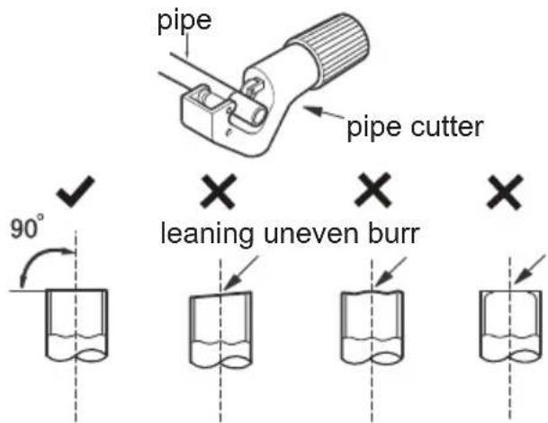
A: Cut the pipe
- Confirm the pipe length according to the distance of indoor unit and outdoor unit.
- Cut pipe with pipe cutter.
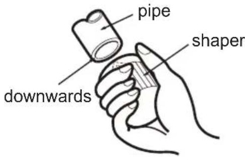
B: Remove the burrs
- Remove the burrs with shaper and prevent the burrs from getting into the pipe.
C: Insulate piping
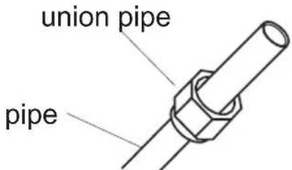
D:Put on the flare nut
- Remove the flare nut on the indoor connection pipe and outdoor valve; install the flare nut on the pipe.
E: Expand the port
- Expand the port with expander.
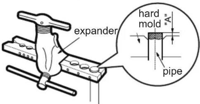
Note:
- "A" is different according to the diameter, please refer to the sheet below:
| Outer diameter In(mm) | A(mm) | |
| Max Min | ||
| 1/4"(Φ6-6.35) | 1.3 | 0.7 |
| 3/8"(Φ9.52) | 1.6 | 1.0 |
| 1/2"(Φ12-12.7) | 1.8 | 1.0 |
| 5/8"(Φ15.8-16) | 2.4 | 2.2 |
F: Inspection
- Check the quality of expanding port. If there is any blemish, expand the port again according to the steps above.
smooth surface
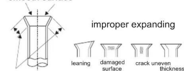
the length is equal
FRIEDRICH
Friedrich Air Conditioning Co.
10001 Reunion Place, Suite 500 - San Antonio, Texas 78216
1.800.541.6645
www.friedrich.com

MODELES
MODULE INTÉRIEURE MWM18Y3J MWM 24Y3J
MODULE EXTERIEURE MRM18Y3J MRM24Y3J
TABLE DES MATIÈRES
△(AUTO), (COOL), (DRY), (FAN) or (HEA
17 BOUTON MODE NUIT
Operation of Remote Controller

BOUTON MODE SENSORIEL
Remote Control Instructions
8
TIMERON:
Remote Control Instructions
14
SOMMEIL AUTOMATIQUE (SLEEP)
Remove the filter as indicated in the fig.
3
Service and Assistance
Tools for installation
Selection of installation location
Grounding requirement
Installation of indoor unit
Step nine: hang the indoor unit
X X X Oblique Irregulier Ebarbure
Friedrich Air Conditioning Co.
10001 Reunion Place, Suite 500 - San Antonio, Texas 78216
1.800.541.6645
www.friedrich.com