
SU100KMBPKX - Electrical panel Tripp Lite - Free user manual and instructions
Find the device manual for free SU100KMBPKX Tripp Lite in PDF.

| Product Type | Maintenance Bypass Panel |
| Model | SU100KMBPKX |
| Compatibility | Used with Tripp Lite UPS for uninterrupted maintenance |
| Rated Voltage | 208Y/120 V AC, 3-phase, 4-wire plus ground |
| Frequency | 60 Hz |
| Rated Current | 225 A minimum, 400 A maximum |
| Short Circuit Rating | 10 kAIC |
| Neutral Bus Rating | 400 A |
| Dimensions (H x W x D) | 800 x 978 x 150 mm (31.5 x 38.5 x 5.89 in) |
| Weight | 50 kg (110 lb) |
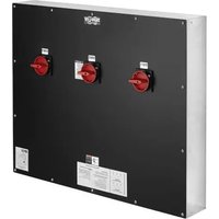
| Enclosure Type | NEMA 1, wall-mount, 16 GA galvanized steel |
| Input/Output | 3-phase, 4 wires with ground conductor |
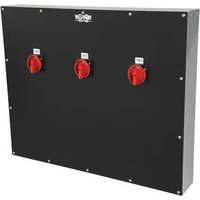
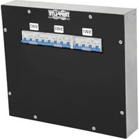
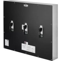
| Number of Switches | 3 three-pole switches (SW1, SW2, SW3) with removable handles |
| Wire Range | Input/Output: 250 MCM to 6 AWG; Neutral: 600 MCM to 6 AWG; Ground: 350 MCM to 6 AWG |
| Torque | Input/Output: 375 in-lb (42.4 Nm); Neutral: 500 in-lb (56.5 Nm); Ground: 375 in-lb (42.4 Nm) |
| Operating Temperature | 0 °C to 40 °C (32 °F to 104 °F) |
| Relative Humidity | 5 to 95% non-condensing |
| Maximum Altitude | 2,255 m (7,400 ft) |
| Approvals | UL/cUL per UL 1778 and CSA C22.2 No. 107.3-14 |
| Warranty | 1-year limited warranty (repair or replacement of defective parts) |
| Maintenance | Visual inspection after short circuit; replace any damaged component; do not re-energize without correcting the cause |
| Safety | Installation and maintenance by qualified personnel only; always de-energize and lockout before servicing |
Frequently Asked Questions - SU100KMBPKX Tripp Lite
User questions about SU100KMBPKX Tripp Lite
0 question about this device. Answer the ones you know or ask your own.
Ask a new question about this device
Download the instructions for your Electrical panel in PDF format for free! Find your manual SU100KMBPKX - Tripp Lite and take your electronic device back in hand. On this page are published all the documents necessary for the use of your device. SU100KMBPKX by Tripp Lite.
USER MANUAL SU100KMBPKX Tripp Lite
Installation and Operation Manual
Maintenance Bypass Panel
Models: SU100KMBPKX, SU120KMBPK, SU160KMBPKX, SU180KMBPKX, SU210KMBPKX
natural_image
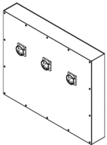
Isometric line drawing of a rectangular enclosure with three circular mounting holes on its side (no text or symbols)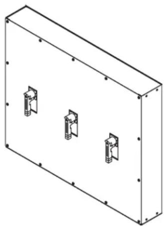
natural_image
Isometric line drawing of a rectangular enclosure with three internal mounting brackets (no text or symbols)Contents
- Introduction 2
- Important Information About This Manual 2
2.1 Manual Symbols 2
- Safety Precautions 2
- Inspection Upon Receipt of Goods 3
4.1 General 3
4.2 Visible Damage 3
4.3 Concealed Damage 3
4.4 Return of Damaged Goods 3
- System Overview 3
- System Specifications 3
6.1 Electrical 3
6.2 Environmental 3
6.3 General Specifications 4
- Installation 4
7.1 Preparation 4
7.1.1 Equipment Inspection 4
7.1.2 Necessary Equipment and Tools 4
7.1.3 Installation Safety Precautions 4
7.1.4 Storage 4
7.2 Installation Steps 4
7.2.1 Equipment Location 4
7.2.2 Equipment Mounting 4
7.2.3 Equipment Connections 5
7.2.4 Pre-Energizing Inspection 5
7.2.5 Energizing 5
-
System Operation 6
-
Maintenance 7
9.1 Short Circuits and Overloads 7
10.Reference Materials 7
11.Warranty 9
Español 10
Français 19
Русский 28


Manufacturing Excellence.
1. Introduction
Tripp Lite would like to thank you for choosing our product for your equipment needs. We know there are a lot of choices and we appreciate the opportunity to supply each of our customers with the highest-quality power products manufactured in the United States today. All of our solutions are factory-tested to the highest standards.
Sales support for future equipment needs or upgrades is provided by our regional sales staff and qualified representatives. All technical questions and service issues should be directed to our main office by visiting www.tripplite.com/support.
Tripp Lite
www.tripplite.com
Technical Support
www.tripplite.com/support
2. Important Information About This Manual
SAVE THESE INSTRUCTIONS!
This manual contains important information that is needed during the installation and maintenance of the system.
2.1 Manual Symbols

Warning:
Indicates information provided to protect the user against personal injury, safety hazards and/or possible equipment damage.

Electrical Hazard:
Indicates that an electrical hazard exists that will result in personal injury or death if instructions are not followed.

Important:
Indicates information provided as an installation or operating instruction or tip, as well as general important installation and system information.
3. Safety Precautions

Before installing or maintaining this equipment, it is extremely important to read this manual and be sure that all equipment drawings and schematics are reviewed and clearly understood. If there are any questions concerning this manual or any of the installation or maintenance procedures and/or requirements, please contact a Tripp Lite representative before proceeding.

Information in this manual is not intended for use as a training manual for nonqualified personnel.

When installing this equipment, always follow all applicable federal, state and local regulations to ensure safe and proper equipment installation.

Only qualified persons should attempt to install or service this equipment. A qualified person is one who has skills and knowledge related to the construction and operation of electrical equipment and installations and has received safety training on the hazards involved.

Equipment installation and maintenance should always be performed with heavily insulated tools. It is also recommended to wear rubber gloves and boots and to use insulating mats to stand on when working on this equipment.

Always wear eye protection when installing or maintaining power equipment.

To avoid personal injury, including electrical shock, severe burns and possible death, all jewelry, including bracelets, rings and watches, must be removed prior to installing or servicing this equipment.

For the safety of others, never leave an open cabinet or panel unattended.

Any modifications to the equipment without authorization by Tripp Lite could result in equipment damage, personal injury or death.

Never work on power equipment while it is energized. De-energize equipment and lock off all power to the equipment before working inside.

Inspection and maintenance should only be performed on equipment that has been de-energized and electrically isolated so that no accidental contact can be made with energized parts.
4. Inspection Upon Receipt of Goods
4.1 General
Special precautions and care have been taken to ensure the system arrives safe and undamaged. However, upon receipt, you should inspect the entire shipment, including the crate and any boxes, for evidence of damage that may have occurred during transit.
4.2 Visible Damage
It is the responsibility of the person receiving the shipment to inventory and fully inspect all materials against the bill of lading or waybill IMMEDIATELY while the carrier representative is still present. Ensure that all items are accounted for, including number of skids and quantity of boxes. Also note any visible external damage that may have occurred during transit. Make all applicable notations on the delivery receipt before signing and file a damage report with the carrier.
4.3 Concealed Damage
Within 3 to 30 days of receipt (depending on courier), unpack the system and check for any concealed damage. Check the materials received against the detailed packing list to verify the quantity and the condition as complete and satisfactory.
Note any damage to the internal packaging. Then request an inspection by the carrier and file a concealed damage claim. If there is a material shortage, visit www.tripplite.com/support to file a claim.
Please contact your shipping company for all shipping damage. Tripp Lite is not responsible for any shipping damage.
4.4 Return of Damaged Goods
Should equipment be damaged and require return to Tripp Lite for repair, a representative will provide instructions along with an RMA number to expedite the return.
An RMA number must be obtained before returning equipment to Tripp Lite.
5. System Overview
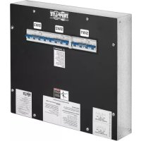
The Tripp Lite Maintenance Bypass Panel (MBP) is used in conjunction with an Uninterruptible Power Supply (UPS) to maintain total continuity of power to connected load circuits when bypass of the UPS equipment is required for performance of regular service and maintenance.
These MBPs are available with current capacities ranging from 225-400 amperes with multiple input voltage options available. These MBP models contain three 3-pole switches.
6. System Specifications

Always refer to the Ratings Label on the equipment for configuration-specific ratings. Equipment specifications and ratings in this document represent typical equipment and may vary from the equipment provided.
6.1 Electrical
Voltage: 208Y/120VAC, 3-Phase, 4-Wire, plus ground
Frequency: 60 Hz
Current: 225A minimum; 400A maximum
Short Circuit Rating: 10kAIC
Neutral Bus Current Rating: 400A
6.2 Environmental
Operating Temperature: 32°F to 104°F (0°C to 40°C)
Relative Humidity: 5% to 95% non-condensing
Altitude: 0 to 7400 ft. (0 to 2255 m) above sea level
6. System Specifications
6.3 General
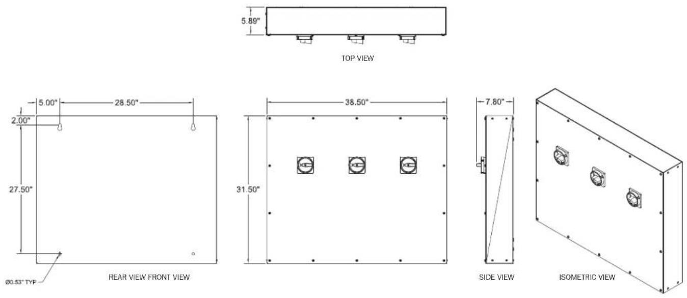
Cabinet Size, H x W x D: 31.5 x 38.5 x 5.89 in. (800 x 978 x 150 mm)
Weight: 110 lb. (50 kg)
7. Installation
7.1 Preparation
7.1.1 Equipment Inspection
Remove the equipment from the packaging material and inspect for any shipping damage that may have been overlooked upon receipt of goods. Verify that the system includes all necessary hardware for installation.
7.1.2 Necessary Equipment and Tools
• Properly insulated tools
• Properly sized and rated mounting hardware
7.1.3 Installation Safety Precautions

Before proceeding with system installation, be sure to review and understand all of the SAFETY PRECAUTIONS in Section 3 of this manual!

AC VOLTAGE WARNING
The input/output voltage in this equipment can be up to 400 VAC. Be sure to fully read and understand this manual and verify that all AC connections are correct and properly torqued. Use extreme caution when installing and maintaining the system!
7.1.4 Storage
If the equipment cannot be immediately installed, it should be stored in a clean and dry indoor location with adequate air circulation and uniform temperature to prevent condensation. If the equipment must be stored for any length of time, it should be covered to protect it from dust, debris and moisture.
7.2 Installation Steps

Before installing or maintaining this system, it is extremely important to read this manual and be sure that all system drawings and schematics are reviewed and clearly understood. If there are any questions concerning this manual or any of the installation or maintenance procedures and/or requirements, please contact a Tripp Lite representative before proceeding.
7.2.1 Equipment Location

This equipment is intended to be installed in a restricted access location.
The permanent location of the equipment must be on a smooth and solid wall surface. Do not locate the equipment against a non-fireproof ceiling. Allow a space of 3 feet between the ceiling and the equipment unless an adequate fireproof shield is provided. Also verify that the selected location will provide working clearances in compliance with article 110.26 of the National Electrical Code (NEC). Environmental conditions of the selected location should also be reviewed. Refer to section 6.2 Environmental for environmental specifications.
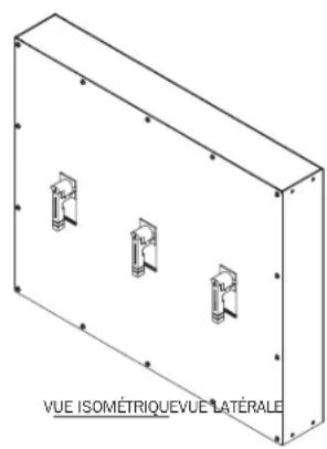
7.2.2 Equipment Mounting
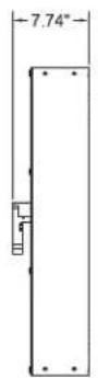
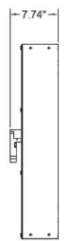
The equipment should be reliably secured to the mounting surface. Do not depend on wooden plugs driven into holes in masonry, concrete, plaster or similar materials in accordance with Article 110.13 of the National Electrical Code (NEC). Secure the equipment utilizing the four 0.53-inch diameter mounting holes located in the back of the equipment. A set of equipment drawings for the specific configuration of the equipment is included inside the equipment. Reference the equipment drawings or mounting hole size and locations. (See drawings in Reference Materials section.)
7. Installation
7.2.3 Equipment Connections

Never work on power equipment while it is energized. De-energize equipment and lock off all power to the equipment before working inside.
The top and bottom panels of the equipment are the recommended designated areas for landing conduit to the equipment. All conduits must be located to avoid interference with structural members and live bus. A set of drawings for the specific configuration of the equipment is included inside the equipment. Reference the equipment drawings in Section 10 Reference Materials.

All conductors are to be sized for 167irc F ( 75irc C) ampacity. When cable is used with temperature ratings above 167irc F/ 75irc C, it shall be sized based on the ampacity of cable rated 167irc F ( 75irc C).

The equipment must be grounded with the appropriately sized conductor in compliance with Article 250 of the National Electrical Code (NEC). The ground conductor should be terminated to the main ground bus bar inside the equipment.
Remove the equipment covers as needed to access the input and output connection points. Where cables enter or exit the equipment or pass through any metal which has magnetic properties, they shall be arranged so all phase and neutral conductors are grouped together and pass through the same opening in compliance with Article 300.20 of the National Electrical Code (NEC). When pulling cable into the equipment, take care not to damage any of the internal components and control wiring. Position the cables inside of the equipment so they are not subject to physical damage and are not forced permanently against the edges of any metal parts. If any cables are in contact with sharp edges, place suitable protective material between the cable and the metal edge to protect the cable insulation.
Using the appropriate tools, strip a length of insulation from the end of the cable sufficient to fit into the full length of the mechanical lug for the designated connection point. If using aluminum conductors, apply an appropriate antioxidant compound to the bare aluminum. Insert the bare conductor into the lug so the bare conductor fills the full length of the mechanical lug body. Tighten the set screw on the mechanical lug and torque to the values indicated on the Torque Values Label located on the equipment.
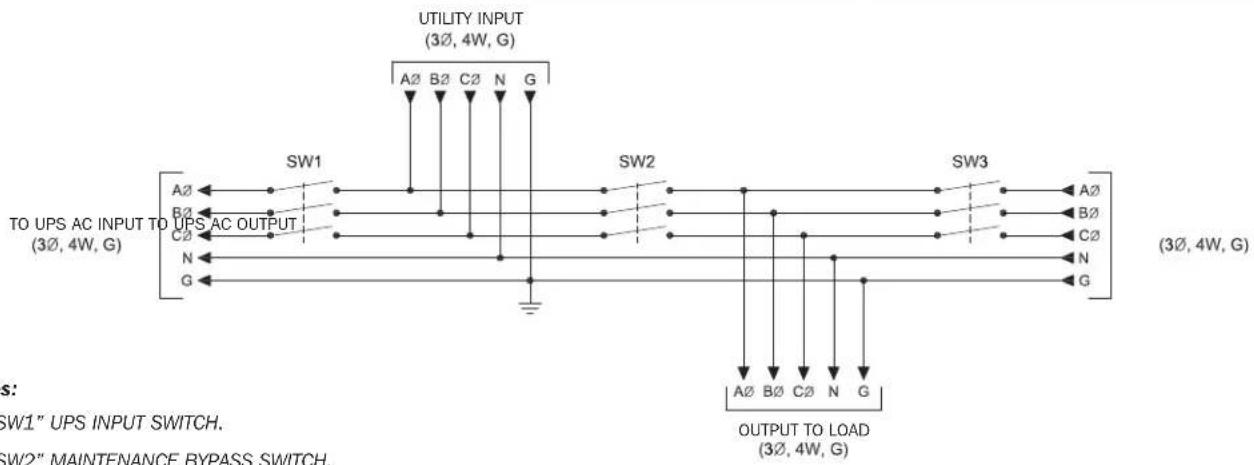
Reference the Equipment Schematic Drawing for information on the required connections between the Maintenance Bypass Panel, the UPS and the critical load.
7.2.4 Pre-Energizing Inspection

Inspection and maintenance should only be performed on equipment that has been de-energized and electrically isolated so that no accidental contact can be made with energized parts.
The top and bottom panels of the equipment are the recommended designated areas for landing conduit to the equipment. All conduits must be located to avoid interference with structural members and live bus. A set of drawings for the specific configuration of the equipment is included inside the equipment. Reference the equipment drawings in Section 10 Reference Materials.
Before energizing the equipment, it must be thoroughly inspected.
- Remove any foreign materials from inside of the equipment including tools, scraps of wire or other debris.
- Visually inspect the equipment for any damage that may have occurred during the installation process. Be sure to inspect all insulators, busbars and other conductors. Do not energize if any damage is found!
- Verify cable phase orientation at all connection points.
- Verify all field cable connections are properly torqued.
- Manually operate all switches to verify proper operation.
- Verify equipment ground connections are properly terminated.
- Review the bypass operating sequence prior to actuating the switches.
- Verify all covers are installed.
7.2.5 Energizing

Hazardous voltages in electrical equipment can cause severe injury or death!

Only qualified persons should attempt to install or service this equipment. A qualified person is one who has skills and knowledge related to the construction and operation of electrical equipment and installations and has received safety training on the hazards involved.

Ensure maximum continuous loads do not exceed 80% of the overcurrent protective device (switches and fuses) ratings employed in other than motor circuits, except for those circuits employing switches marked as suitable for continuous operation at 100% of their ratings.
Extreme hazards can exist when energizing electrical equipment. Take all precautions necessary to protect people and property when energizing this equipment. Before energizing the equipment, open/turn off all switches. Refer to the UPS manual for proper startup procedures.
8. System Operation

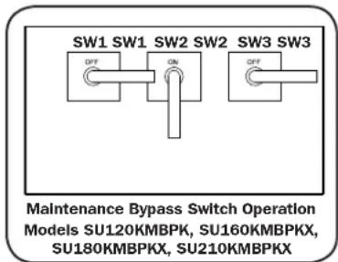
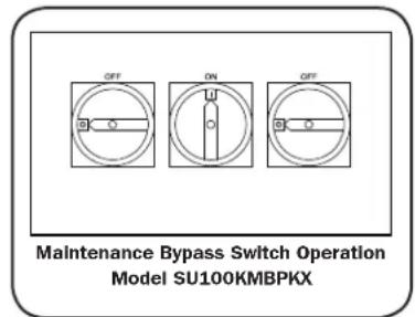
Do not operate the "SW2" switch unless the UPS is in BYPASS mode! Failure to follow the operating instructions for this equipment could result in equipment damage, fire, severe injury or death!
Normal Operation
The "SW1" Switch is closed/on. The "SW2" Switch is Open/Off. The "SW3" Switch is closed/on.
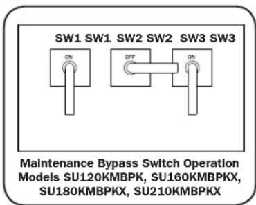
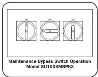
POSITION 1 (NORMAL OPERATION)
Transfer to Maintenance Bypass
- Transfer the UPS to the Bypass mode before proceeding.
- Close/turn on the "SW2" switch.
- Open/turn off the "SW3" switch.
- The UPS is now ready for routine maintenance.
- If further maintenance requires a total shutdown of the UPS and isolation from the input, the "SW1" switch must be opened/turned off and the battery supply to the UPS must be disconnected. Refer to your UPS manual for proper shutdown procedures.
POSITION 2 (IN EXTERNAL BYPASS)
Return to Normal Operation
- If the "SW1" switch was opened/turned off for maintenance, then follow the UPS manual for proper startup procedures. To restore input power to the UPS, close/turn on the "SW1" switch. Make sure the UPS is in Bypass mode before proceeding.
- Close/turn on the "SW3" switch.
- Open/turn off "SW2" switch.
- Transfer the UPS from Bypass mode to Line model (Online mode).
Note: To use Bypass position contacts, refer to your UPS system's owner's manual for connection instructions.
9. Maintenance

Before installing or maintaining this equipment, it is extremely important to read this manual and be sure that all equipment drawings and schematics are reviewed and clearly understood. If there are any questions concerning this manual or any of the installation or maintenance procedures and/or requirements, please contact a Tripp Lite representative before proceeding.

Inspection and maintenance should only be performed on equipment that has been de-energized and electrically isolated so that no accidental contact can be made with energized parts.
9.1 Short Circuits and Overloads

Do not attempt to re-energize a switch after a short circuit or overload until the cause of the event has been identified and corrected. Failure to correct the cause of the event may result in equipment damage, fire, severe injury or death.
Switches will normally prevent electrical damage except at the point where the short circuit occurred. High mechanical stress developed by short circuit currents may cause damage to conductors, insulation or other components. After a fault, thorough inspection of the entire system must be made to verify that there is no damage.
Switches which performed the short circuit interruption must be inspected for possible damage. Do not disassemble the switch or open the switch trip unit.
Replace all damaged insulation materials, conductors and switches. It is recommended that the equipment be hipot tested prior to being placed back in service.
10. Reference Materials
Notes:
APPROXIMATE WEIGHT: 110 LB. (50 KG)
- ASSEMBLY IS UL/CUL LISTED PER UL 1778 AND C22.2 NO. 107.3-14.
- NEMA 1 WALL-MOUNT ENCLOSURE
-
THE BOX AND TRIM ARE CONSTRUCTED OF GALVANIZED 16GA STEEL.
-
THE SWITCHES HAVE REMOVABLE HANDLES TO ALLOW THE TRIM COVER TO BE REMOVED FOR INTERNAL PANEL ACCESS.
-
THE PANEL IS TO BE MOUNTED THROUGH THE ∅0.53" HOLES IN THE BACK OF THE ENCLOSURE.
-
THE SWITCH HANDLES CAN BE PADLOCKED TO LOCK THE SWITCH (MODELS SU120KMBPK, SU160KMBPKX, SU180KMBPKX, SU210KMBPKX)
Models SU120KMBPK, SU160KMBPKX, SU180KMBPKX, SU210KMBPKX

10. Reference Materials
Model SU100KMBPKX
| WIRE RANGE & TORQUE VALUE SUMMARY | ||
| MECHANICAL LUG CONNECTIONS WIRE RANGE TORQUE VALUE | ||
| INPUT #6 - 250 MCM 375 in-lbs. (42.4 Nm) | ||
| OUTPUT #6 - 250 MCM 375 in-lbs. (42.4 Nm) | ||
| NEUTRAL #2 - 600 MCM 500 in-lbs. (56.5 Nm) | ||
| GROUND #6 - 350 MCM 375 in-lbs. (42.4 Nm) | ||
| GROUND #22 - #10 AWG 16 in-lbs. (1.8 Nm) | ||
flowchart
graph TD
    A["UTILITY INPUT (3Ø, 4W, G)"] --> B["A2 B2 C2 N G"]
    B --> C["SW1"]
    B --> D["SW2"]
    B --> E["SW3"]
    C --> F["A2"]
    C --> G["B2"]
    C --> H["C2"]
    D --> I["N"]
    D --> J["G"]
    E --> K["A2"]
    E --> L["B2"]
    E --> M["C2"]
    E --> N["N"]
    E --> O["G"]
    F --> P["TO UPS AC INPUT TO UPS AC OUTPUT (3Ø, 4W, G)"]
    G --> P
    H --> P
    I --> P
    J --> P
    K --> P
    L --> P
    M --> P
    N --> P
    O --> P
    P --> Q["OUTPUT TO LOAD (3Ø, 4W, G)"]
    style A fill:#f9f,stroke:#333
    style B fill:#ccf,stroke:#333
    style C fill:#cfc,stroke:#333
    style D fill:#fcc,stroke:#333
    style E fill:#cff,stroke:#333
    style F fill:#ffc,stroke:#333
    style G fill:#ffc,stroke:#333
    style H fill:#ffc,stroke:#333
    style I fill:#ffc,stroke:#333
    style J fill:#ffc,stroke:#333
    style K fill:#ffc,stroke:#333
    style L fill:#ffc,stroke:#333
    style M fill:#ffc,stroke:#333
    style N fill:#ffc,stroke:#333
    style O fill:#ffc,stroke:#333
Notes:
- "SW1" UPS INPUT SWITCH.
- "SW2" MAINTENANCE BYPASS SWITCH.
- "SW3" MAINTENANCE ISOLATION SWITCH.
- MODELS SU120KMBPK, SU160KMBPKX, SU180KMBPKX, SU210KMBPKX – “SW2” AND “SW3” SWITCHES ARE CONNECTED WITH (2) 1/0 WIRES PER PHASE. MODEL SU100KMBPKX – “SW2” AND “SW3” SWITCHES ARE CONNECTED WITH (1) 1/0 WIRE PER PHASE.
- MODELS SU120KMBPK, SU160KMBPKX, SU180KMBPKX, SU210KMBPKX - "SW1" AND "SW3" SWITCH LUGS ACCEPT (2) #6 - 250 MCM WIRE PER PHASE. MODEL SU100KMBPKX - "SW1" AND "SW3" SWITCH LUGS ACCEPT (1) #6 - 350 MCM WIRE PER PHASE.
- GROUND LUG ACCEPTS (4) #6 - 350 MCM WIRE.
- MECHANICAL LUGS USED FOR THE UTILITY INPUT AND THE OUTPUT TO LOAD HAVE THE SAME WIRE RANGE AS THE SWITCHES.
- THIS DRAWING IS TO BE USED FOR ELECTRICAL PURPOSES ONLY AND DOES NOT REPRESENT THE ACTUAL MECHANICAL LAYOUT OF THE EQUIPMENT.
11. Warranty
LIMITED WARRANTY AND EXCLUSIONS
Tripp Lite strives to produce quality products at reasonable prices. If you are not satisfied with our product because of a defect, we will repair or replace the defective part or parts free of charge for a period of one year from the date of purchase. In the event you claim that the product contains a defect, simply notify Tripp Lite of the defect, and we will arrange for repair or replacement. The sole and exclusive remedy against Tripp Lite relating in any way to a product defect shall be the repair or replacement of defective parts as provided for under this LIMITED WARRANTY. No other remedy, including, but not limited to, incidental or consequential damages for lost profits, lost sales, injury to person or property, or any other incidental or consequential loss, is available. This LIMITED WARRANTY shall not be deemed to have failed of its essential purpose so long as Tripp Lite is willing and able to repair or replace defective parts in the manner prescribed in this LIMITED WARRANTY.
Certain integrated products, which are not manufactured by Tripp Lite, will be warranted by the applicable manufacturer. These warranties shall be between the manufacturer and the user. Terms and conditions may vary. These integrated products include, but may not be limited to, the following products: Batteries, Inverters and UPS Systems.
Use of this equipment in life support applications where failure of this equipment can reasonably be expected to cause the failure of the life support equipment or to significantly affect its safety or effectiveness is not recommended.
Any action for breach relating to the sale of a Tripp Lite product must be commenced within one year after the cause of action has been accrued.
THIS LIMITED WARRANTY IS IN LIEU OF ANY OTHER WARRANTY, EXPRESS OR IMPLIED, AND ALL SUCH WARRANTIES ARE EXCLUDED, INCLUDING, BUT NOT LIMITED TO, ANY IMPLIED WARRANTY OF MERCHANTABILITY OR FITNESS FOR A PARTICULAR PURPOSE.
Tripp Lite has a policy of continuous improvement. Specifications are subject to change without notice. Photos and illustrations may differ slightly from actual products.


Manufacturing Excellence.
1111 W. 35th Street, Chicago, IL 60609 USA • www.tripplite.com/support
natural_image
Isometric line drawing of a rectangular enclosure with three circular mounting holes on its side (no text or symbols)
natural_image
Isometric line drawing of a rectangular enclosure with three internal mounting brackets (no text or symbols)Índice
www.tripplite.com/support

natural_image
Isometric view of a rectangular enclosure with three internal components, labeled 'VISTA ISOMETRICAVISTA LATERAL' at the bottom (no other text or symbols)natural_image
Isometric line drawing of a rectangular enclosure with three circular mounting holes on its side (no text or symbols)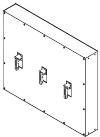
natural_image
Isometric line drawing of a rectangular enclosure with three internal compartments (no text or symbols)Table des matières
1111 W. 35th Street, Chicago, IL 60609 USA • www.tripplite.com/support
www.tripplite.com/support
CONSERVEZ CES INSTRUCTIONS!
natural_image
Isometric view of a rectangular enclosure with three small mechanical components on its side (no text or symbols visible)1111 W. 35th Street, Chicago, IL 60609 USA • www.tripplite.com/support
natural_image
Isometric line drawing of a rectangular enclosure with three circular mounting holes on its side (no text or symbols)
natural_image
Isometric line drawing of a rectangular enclosure with three internal compartments (no text or symbols)Содержание
1111 W. 35th Street, Chicago, IL 60609 USA • www.tripplite.com/support
1. Введение
www.tripplite.com/support

1111 W. 35th Street, Chicago, IL 60609 USA • www.tripplite.com/support
- Installation and Operation Manual
- Maintenance Bypass Panel
- Contents
- Introduction
- Tripp Lite
- Technical Support
- Important Information About This Manual
- SAVE THESE INSTRUCTIONS!
- Manual Symbols
- Warning:
- Electrical Hazard:
- Important:
- Safety Precautions
- Inspection Upon Receipt of Goods
- General
- Visible Damage
- Concealed Damage
- Return of Damaged Goods
- System Overview
- System Specifications
- Electrical
- Environmental
- General
- Installation
- Preparation
- Equipment Inspection
- Necessary Equipment and Tools
- Installation Safety Precautions
- AC VOLTAGE WARNING
- Storage
- Installation Steps
- Equipment Location
- Equipment Mounting
- Equipment Connections
- Pre-Energizing Inspection
- Energizing
- System Operation
- Normal Operation
- Transfer to Maintenance Bypass
- Return to Normal Operation
- Maintenance
- Short Circuits and Overloads
- Reference Materials
- Notes:
- Warranty
- LIMITED WARRANTY AND EXCLUSIONS
- Índice
- Table des matières
- CONSERVEZ CES INSTRUCTIONS!
- Содержание
- Введение
Brand : Tripp Lite
Model : SU100KMBPKX
Category : Electrical panel