
B3028HX8H4K - HDMI switch Tripp Lite - Free user manual and instructions
Find the device manual for free B3028HX8H4K Tripp Lite in PDF.

| Product Type | HDMI Matrix Switch |
| Brand | Tripp Lite |
| Model | B3028HX8H4K (B302-8HX8H-4K) |
| HDMI Inputs | 8 (female) |
| HDMI Outputs | 8 (female) |
| Maximum Resolution | 4096 × 2160 @ 60 Hz (4K) |
| HDMI Bandwidth | 18 Gbit/s |
| HDCP | HDCP 2.2 |
| Power Supply | DC 12V, 4A (power adapter included) |
| Power Consumption | 40.5 W |
| Dimensions (W × D × H) | 440 × 250 × 44 mm |
| Weight | 3,145 g |
| Operating Temperature | 0 to 45 °C |
| Storage Temperature | -10 to 80 °C |
| Operating Humidity | 10 to 85% RH (non-condensing) |
| Storage Humidity | 5 to 90% RH (non-condensing) |
| Control Methods | Front panel, IR remote, RS-232, TCP/IP (GUI) |
| Additional Functions | Stereo audio extraction, configurable EDID, Smart/Default mode, panel lock |
| Warranty | 3-year limited |
Frequently Asked Questions - B3028HX8H4K Tripp Lite
S1X2. to send input 1 to output 2. End each command with a period.User questions about B3028HX8H4K Tripp Lite
0 question about this device. Answer the ones you know or ask your own.
Ask a new question about this device
Download the instructions for your HDMI switch in PDF format for free! Find your manual B3028HX8H4K - Tripp Lite and take your electronic device back in hand. On this page are published all the documents necessary for the use of your device. B3028HX8H4K by Tripp Lite.
USER MANUAL B3028HX8H4K Tripp Lite
HDMI Matrix Switch/Splitters with Audio Extractor, IP Access and Multi-Resolution Support
Model: B302-4HX4H-4K, B302-8HX8H-4K
Español 15 • Français 29 • Русский 43
WARRANTY REGISTRATION
Register your product today and be automatically entered to win an ISOBAR ® surge protector in our monthly drawing!
tripplite.com/warranty


1111 W. 35th Street, Chicago, IL 60609 USA • tripplite.com/support
Copyright © 2021 Tripp Lite. All rights reserved.
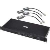
Package Contents
• B302-4HX4H-4K or B302-8HX8H-4K HDMI Matrix Switch/Splitter
- IR Remote Control
- IR Receiver Cable, 4 ft.
• International Power Supply (Input: 100–240V)
• (x4) International Plug Adapters (North America, U.K., Europe, Australia)
- Mounting Hardware
- Driver CD
- Owner's Manual
Optional Accessories
• P569-XXX-CERT High-Speed HDMI 2.0 Cables
• P312-Series 3.5 mm Audio Cables
• N202-Series Cat6 24 AWG Solid-Wire Patch Cables
Product Features
- Shares true 4K video from 4 different HDMI sources among 4 separate displays (B302-4HX4H-4K) or 8 different HDMI sources among 8 separate displays (B302-8HX8H-4K)
- Displays any audio/video signal on any display or the same signal on all displays
• Supports true 4K resolutions up to 4096 x 2160 @ 60 Hz
• Transmits analog stereo audio - Switches between sources and displays via front-panel pushbuttons, IR remote control, RS-232 serial commands or control software
- Multi-resolution support allows mixing and matching of monitors of various resolutions
• HDR (High Dynamic Range) offers richer contrast and expanded color accuracy - Audio extraction allows connection of speakers, amplifiers or sound bars
- Remotely access the software GUI by configuring your network to match the pre-assigned IP address
Panel Descriptions
The following panels depict the 8x8 HDMI Matrix Switch/Splitter. It is identical to the 4x4 model, except with 4 more input and output ports.
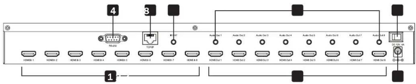
1 HDMI Inputs – Connect up to 8 HDMI source devices.
2 HDMI Outputs – Connect up to 8 HDMI display devices.
3 DC 12V – Connect the included 12V DC power supply.
4 RS-232 Port – Connect a PC or laptop to send RS-232 serial commands to the unit via terminal.
5 TCP/IP Port – Connect a PC or laptop via Cat6 cable to remotely control the unit via GUI.
6 IR EXT – Connect the included IR Receiver Cable for IR signal reception from the included IR Remote Control.
7 Audio Outputs – Connect up to 8 sets of speakers or amplifiers.
8 Power – Switch to turn the unit on and off.
![graph LR A["TRIPP-LITE 8x8 HDMI MATRIX SWITCH<br>Model: B302-8HX8H-4K"] --> B["9"] B --> C["IN/OUT Select"] C --> D["ADD Select"] D --> E["12"] E --> F["LOCK"] F --> G["R"] style A fill:#f9f,stroke:#333 style B fill:#ccf,stroke:#333 style C fill:#cfc,stroke:#333 style D fill:#fcc,stroke:#333 style E…](/content/2026/04/585534/images/5a8655b92039a2617e6a8dbf50fea92e25fb2cf96c3a39c1a0dad6538dcdea17.jpg)
9 LCD Screen – Displays the unit's information and settings.
10 In/Out Select – Let you mix and match any input to any output. Press "ALL" to send one input to all connected displays.
1.1 EDID Select – Let you set EDID information for the Input and Output ports.
12 Lock – Locks all front-panel buttons to prevent accidental changes. Press “LOCK” again to unlock buttons.
13 Enter – Press to confirm commands.
14 IR - IR signal receptor for the included remote control.
Installation
Refer to the following steps and diagram to set up your HDMI matrix switch installation.
Note: Before making any connections, make sure power to all devices connected to the switch is turned off.
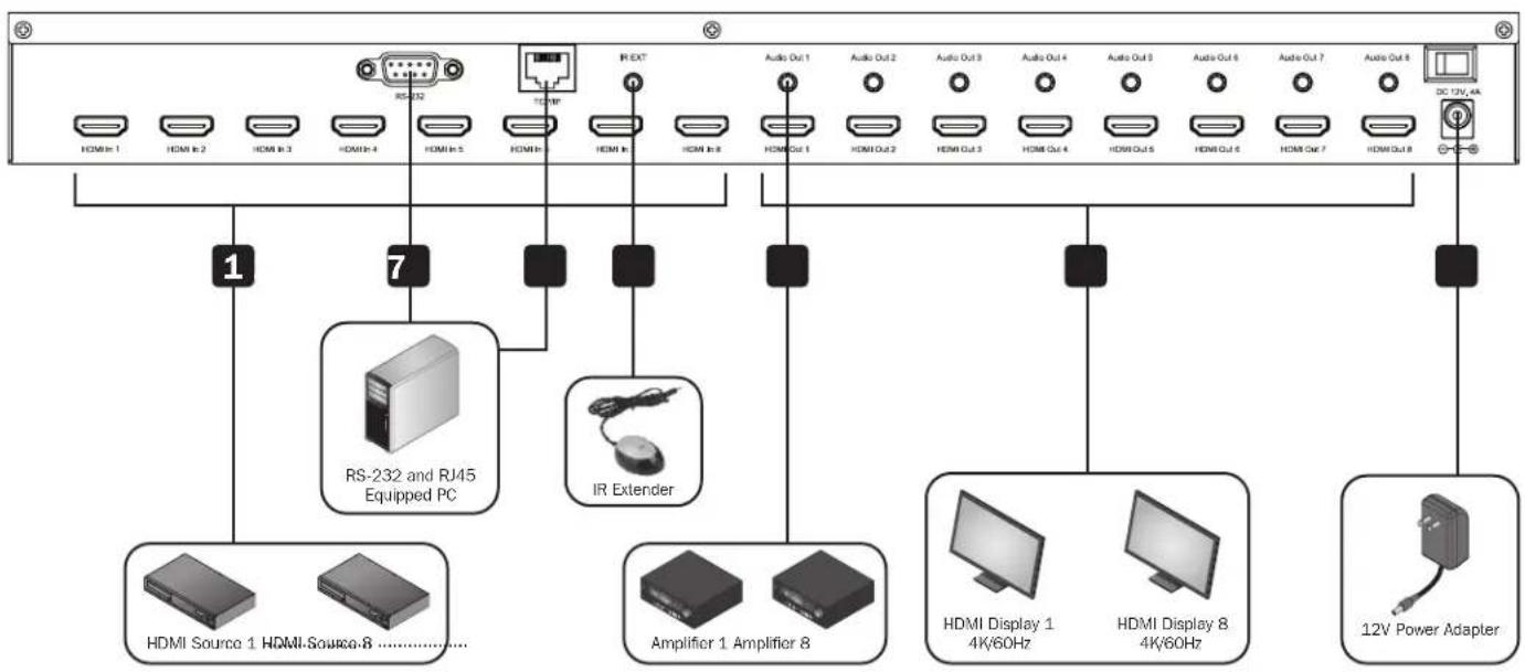
1 Connect up to 8 (B302-8HX8H-4K) or 4 (B302-4HX4H-4K) HDMI sources to the switch with user-supplied cables.
2 Connect up to 8 (B302-8HX8H-4K) or 4 (B302-4HX4H-4K) HDMI displays to the switch with user-supplied cables.
3 (Optional) Connect up to 8 (B302-8HX8H-4K) or 4 (B302-4HX4H-4K) speakers or amplifiers to the switch with user-supplied 3.5 mm audio cables.
4 (Optional) Connect a PC or laptop to the RS-232 port to control the switch via RS-232 commands.
5 (Optional) Connect a PC or laptop to the TCP/IP port with a user-supplied Cat6 cable to control the switch via the GUI.
6 (Optional) Connect the included IR Receiver Cable to the IR EXT port.
7 Connect the included power supply to the 12V DC port and turn on the power using the power switch. Within 20–30 seconds, each input signal will be displayed with its corresponding output port.
Operation
The following instructions are for the 8x8 HDMI Matrix Switch/Splitter, but apply equally to the 4x4 model.
The B302-Series HDMI Matrix Switch/Splitter features three different methods of control:
1) Front-panel pushbuttons
2) IR remote control
3) TCP/IP or RS-232 control via PC or laptop
Front-Panel Pushbuttons
The following section describes how to change the inputs and outputs manually.
*INPUT 12345678 *OUTPUT 12345678
1) To change an input to a specific output, press the desired input (IN 1–8), then the desired output (OUT 1–8). Press "ENTER" to confirm the new settings.
2) If you wish to send one input to more than one output display, press the desired input (IN 1-8), then the desired outputs (OUT 1–8). Once you have selected all the desired outputs, press "ENTER" to confirm the setting changes. To select all the outputs at once, press "ALL."
3) To preset the output EDID settings of one or all inputs, press the desired input (IN 1–8), then "EDID MENU." The LCD screen will display the input source settings as shown below. Press "UP/DOWN" to select a preset EDID. Please see EDID Table for a list of all the preset resolutions. Hit "ENTER" to confirm the setting.
*IN : 1 4KX2K(444)/60Hz
4) To enter the output mode selection menu, press "UP." In the menu, users can choose between Default and Smart mode.
a) Default: All displays are defaulted to output 4K x 2K @ 60 Hz or the user-defined EDID setting.
b) Smart: Outputs the lowest capable resolution of the connected displays.
MODE: Default
MODE: Smart
To switch the mode, press "DOWN." By default, the unit comes preset in Default mode.
Operation
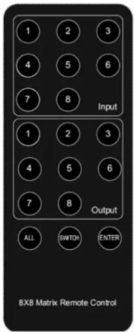
IR Remote Control
The following section describes how to operate the remote. "N" indicates a number value (1–8). "+" indicates continuous pressing. There is no "+" button.
1) The format of switching channels (inputs to outputs) with the remote control is as follows: Input (N) + Switch + Output (N), Input (N) + Switch + Output (N), .... + Enter. For example: If you wish to send Input 1 to Output 2 and Input 2 to Output 4, the sequence will be: Input (1) + Switch + Output (2) + Input (2) + Switch + Output (4) + Enter.
2) To select multiple outputs for one input, an example would be:
Input (1) + Switch + Output (2) + Output (5) + Output (8) + Enter.
3) "ALL" is the shortcut button to select all output channels (displays). It works in the following fashion: ALL + Input (N) + Enter.
TCP/IP GUI Control
The GUI Control software is available on the included CD and at triplite.com. GUI software is not compatible with macOS ® .
1) Run the dedicated GUI software on the target computer to be used.
2) Set the correct COM port number and the following communication parameters: 9600 bps, 1 start bit, 1 end bit, no check bit. Set the data format as ASCII and open the serial port.
3) The Matrix Control System has four different tabs. Each one will be explained in the following steps.
Operation
Switch Interface: Scene entering and configuring.
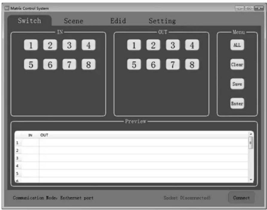
Select the inputs and outputs through the IN/OUT area. The selections will be displayed in the table below.
- ALL: Shortcut button to select all outputs.
- Clear: Clear the contents of the table.
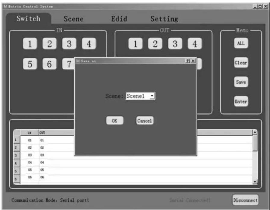
- Save: Save the current scene of the table.
- Enter: Enter the current scene.
Operation
Scene Interface: Scene selection, current scene and recall.
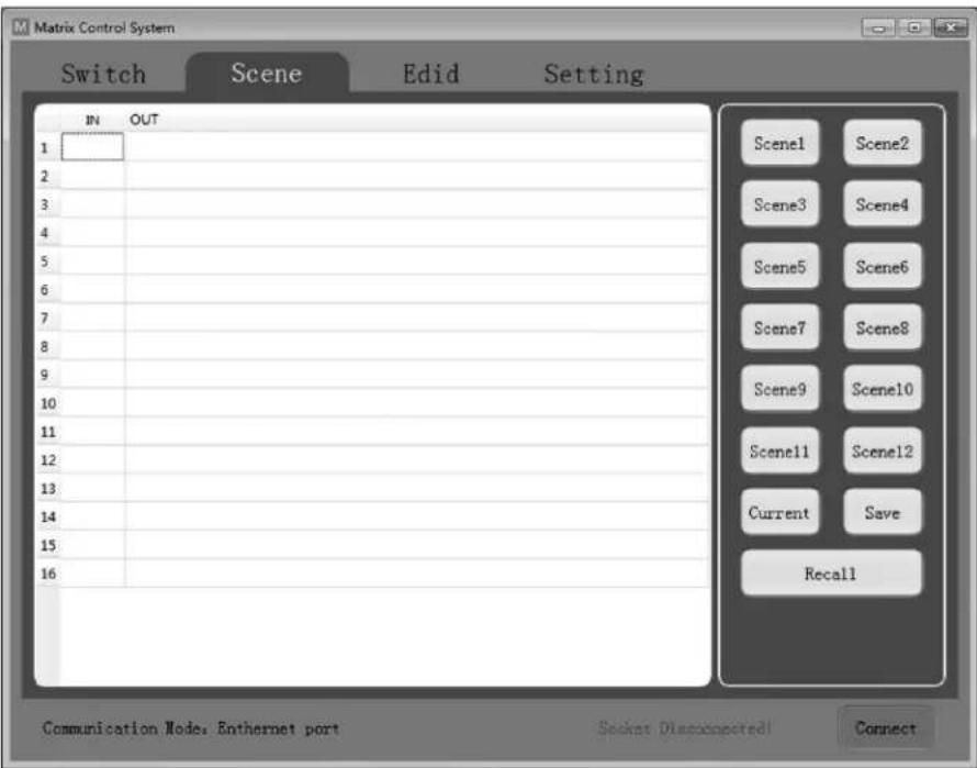
The table on the left side of the interface displays the current scene or the scene that is recalled.
- Scene1-12: User-saved scenes.
- Current: Obtain the current scene of the device.
- Save: Save the current obtained scene of the device.
- Recall: Recall the last scene selected.
Operation
EDID Interface: EDID management.
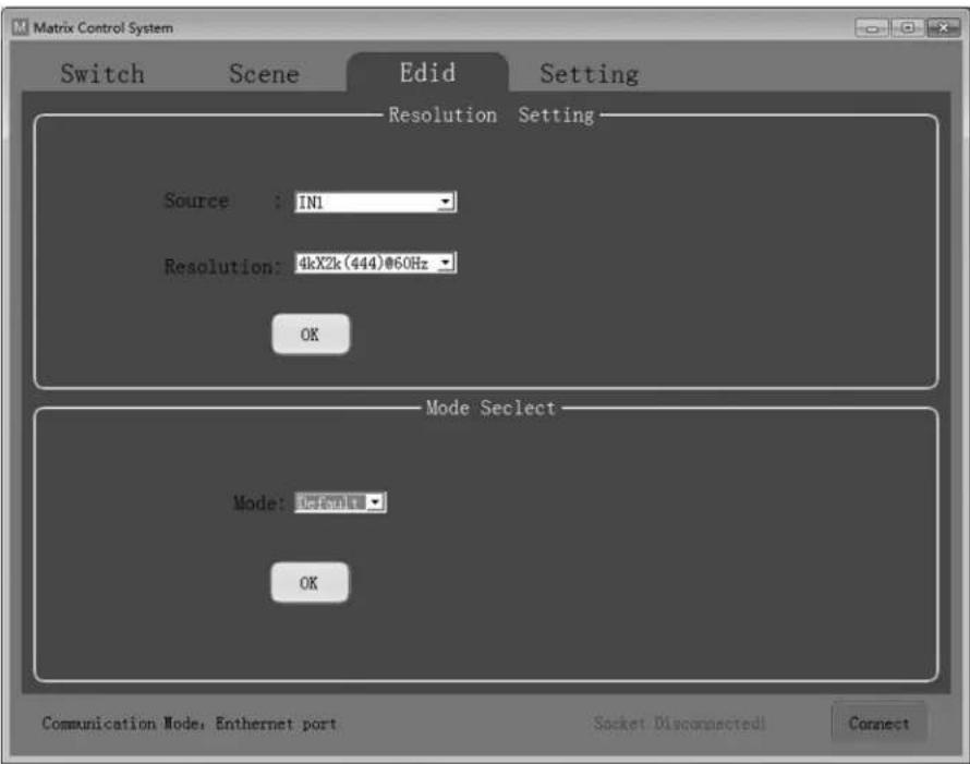
Set the output resolution of each input as well as the mode.
- Source: IN1-8 or IN1-4.
- Resolution: See EDID Table for a full list of available options to choose from.
- Mode: Set the output mode to either Default or Smart.
Operation
Setting Interface: RS-232 and TCP/IP Settings.
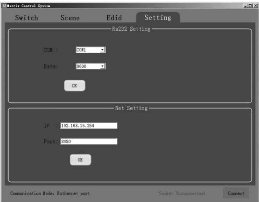
The default communication mode is the RJ45 Ethernet port. Users can configure the communication mode through the RS-232 and Net Setting boxes. Click "OK" in the corresponding box to set the desired communication mode, then click "Connect" to connect. The status bar should change, as shown below.

RS-232 Setting
To control the switch using RS-232 commands, ensure the following communication parameters are set: 9600 bps, 1 start bit, 1 end bit, no check bit. Set the data format as ASCII and open the serial port.
Net Setting
The B302-4HX4H-4K and B302-8HX8H-4K come with a pre-assigned static IP address. They can be accessed remotely by configuring your network to match the pre-assigned IP address style. Simply connect a user-supplied RJ45 cable between the matrix switch and your target computer, and then configure your network settings (IPv4) accordingly.
Note: The pre-assigned IP address will never change even if you disconnect and reconnect the target computer.
Operation
RS-232 Control Commands:
1) In the table below, "a" represents Input and "b" represents Output. The number value range of "a" and "b" depends on the number of inputs and outputs of the controlled matrix. If out of range, it is considered a command input error, and the unit will not execute the command.
2) Please note there is a punctuation mark (.) at the end of every command. This cannot be omitted.
3) Note the uppercase and lowercase letters.
| Control Command Description Instruction/Function | ||
| N. Get the number of channels of the current matrix. | Send the command “N.” and the unit will return “N8.” with 8 representing 8x8 matrix. | |
| C. Get the current state of the matrix. | Send the command “C.” If the current state is 1→1,2→2,3→3,4→4,5→5,6→6,7→8,8→7, the unit will return C1X1, 2X2, 3X3, 4X4 ,5X5, 6X6, 7X8, 8X7. | |
| SaXb. Switch Input | “a” to Output “b.” Send the command and “S1X2.” and the unit will switch Input 1 to Output 2. | |
| Sa1Xb1, a2Xb2, a3Xb3. | Switch input a1, a2, a3 to corresponding output b1, b2, b3. | Send the command “S1X3, 1X4.” and the unit will switch Input 1 to Output 3, 4. |
| Mc. Switch between Default and Smart EDID modes. “c” = 0 = Default mode “c” = 1 = Smart mode | Send the command “M1.” and the unit will switch EDID mode to Smart Mode. | |
| IaEd. Set EDID of Input “a” to EDID No. “d.” | Send the command “I2E4.” and the unit will set EDID of Input 2 as EDID No. 4 (See EDID Table) | |
Operation
EDID Table
| No. Preset EDID | |
| 1 800 x 600/60 Hz | |
| 2 1024 x 768/60 Hz | |
| 3 1152 x 864/75 Hz | |
| 4 1280 x 720/60 Hz | |
| 5 1280 x 768/60 Hz | |
| 6 1280 x 800/60 Hz | |
| 7 1280 x 1024/60 Hz | |
| 8 1360 x 768/60 Hz | |
| 9 1366 x 768/60 Hz | |
| 10 1600 x 900/60 Hz | |
| 11 1600 x 1200/60 Hz | |
| 12 1680 x 1050/60 Hz | |
| 13 1920 x 1080/60 Hz | |
| 14 1920 x 1200/60 Hz | |
| 15 1920 x 1440/60 Hz | |
| 16 2560 x 1080/60 Hz | |
| 17 2560 x 1600/60 Hz | |
| 18 4K x 2K (444)/30 Hz | |
| 19 4K x 2K (420)/60 Hz | |
| 20 4K x 2K (8b)/60 Hz | |
| 21 4K x 2K (444)/60 Hz | |
Specifications
| Models B302-4HX4H-4K / B302-8HX8H-4K | |
| Input (Female) (x4) HDMI / (x8) HDMI | |
| Output (Female) (x4) HDMI / (x8) HDMI | |
| Maximum Resolution 4096 x 2160 @ 60 Hz (4K x 2K) | |
| HDMI Bandwidth 18 Gbps | |
| HDCP Specification HDCP 2.2 | |
| Operating Temperature 32° to 113°F (0° to 45°C) | |
| Storage Temperature 14° to 176°F (-10° to 80°C) | |
| Operating Humidity 10% to 85% RH, Non-Condensing | |
| Storage Humidity 5% to 90% RH, Non-Condensing | |
| Power Input DC 12V 3A / DC 12V 4A | |
| Power Consumption 24.2W / 40.5W | |
| Dimensions (H x W x D) 440 x 200 x 44 mm / 440 x 250 x 44 mm | |
| Weight 2477 g / 3145 g | |
Warranty and Product Registration
3-Year Limited Warranty
Seller warrants this product, if used in accordance with all applicable instructions, to be free from original defects in material and workmanship for a period of 3 years from the date of initial purchase. If the product should prove defective in material or workmanship within that period, Seller will repair or replace the product, at its sole discretion.
THIS WARRANTY DOES NOT APPLY TO NORMAL WEAR OR TO DAMAGE RESULTING FROM ACCIDENT, MISUSE, ABUSE OR NEGLECT. SELLER MAKES NO EXPRESS WARRANTIES OTHER THAN THE WARRANTY EXPRESSLY SET FORTH HEREIN. EXCEPT TO THE EXTENT PROHIBITED BY APPLICABLE LAW, ALL IMPLIED WARRANTIES, INCLUDING ALL WARRANTIES OF MERCHANTABILITY OR FITNESS, ARE LIMITED IN DURATION TO THE WARRANTY PERIOD SET FORTH ABOVE; AND THIS WARRANTY EXPRESSLY EXCLUDES ALL INCIDENTAL AND CONSEQUENTIAL DAMAGES. (Some states do not allow limitations on how long an implied warranty lasts, and some states do not allow the exclusion or limitation of incidental or consequential damages, so the above limitations or exclusions may not apply to you. This warranty gives you specific legal rights, and you may have other rights which vary from jurisdiction to jurisdiction.)
WARNING: The individual user should take care to determine prior to use whether this device is suitable, adequate or safe for the use intended. Since individual applications are subject to great variation, the manufacturer makes no representation or warranty as to the suitability or fitness of these devices for any specific application.
Product Registration
Visit tripplite.com/warranty today to register your new Tripp Lite product. You'll be automatically entered into a drawing for a chance to win a FREE Tripp Lite product!*
* No purchase necessary. Void where prohibited. Some restrictions apply. See website for details.
Tripp Lite has a policy of continuous improvement. Specifications are subject to change without notice. Photos and illustrations may differ slightly from actual products.


1111 W. 35th Street, Chicago, IL 60609 USA • tripplite.com/support
20-10-226 • 93-3CA2_RevB
1111 W. 35th Street, Chicago, IL 60609, EE UU • tripplite.com/support
Operación
1111 W. 35th Street, Chicago, IL 60609, EE UU • tripplite.com/support
20-10-226 • 93-3CA2_RevB
1111 W. 35th Street, Chicago, IL 60609 USA tripplite.com/support
Fonctionnement
Réglage RS-232
1111 W. 35th Street, Chicago, IL 60609 USA tripplite.com/support
20-10-226 • 93-3CA2_RevB
1111 W. 35th Street, Chicago, IL 60609 USA - tripplite.com/support
- HDMI MATRIX SWITCH/SPLITTERS WITH AUDIO EXTRACTOR, IP ACCESS AND MULTI-RESOLUTION SUPPORT
- WARRANTY REGISTRATION
- PACKAGE CONTENTS
- OPTIONAL ACCESSORIES
- PRODUCT FEATURES
- PANEL DESCRIPTIONS
- INSTALLATION
- OPERATION
- FRONT-PANEL PUSHBUTTONS
- IR REMOTE CONTROL
- TCP/IP GUI CONTROL
- RS-232 SETTING
- NET SETTING
- RS-232 CONTROL COMMANDS
- SPECIFICATIONS
- WARRANTY AND PRODUCT REGISTRATION
- 3-YEAR LIMITED WARRANTY
- PRODUCT REGISTRATION
- OPERACIÓN
- FONCTIONNEMENT
- RÉGLAGE RS-232
Brand : Tripp Lite
Model : B3028HX8H4K
Category : HDMI switch