SMX1050SLT - Inverter Tripp Lite - Free user manual and instructions
Find the device manual for free SMX1050SLT Tripp Lite in PDF.

User questions about SMX1050SLT Tripp Lite
0 question about this device. Answer the ones you know or ask your own.
Ask a new question about this device
Download the instructions for your Inverter in PDF format for free! Find your manual SMX1050SLT - Tripp Lite and take your electronic device back in hand. On this page are published all the documents necessary for the use of your device. SMX1050SLT by Tripp Lite.
USER MANUAL SMX1050SLT Tripp Lite
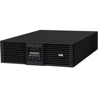
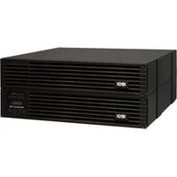
Intelligent, Line-Interactive UPS System
• 220/230/240V Pure Sine Wave Input/Output
Agency Models
AG-0020, AG-0021, AG-0022
Not suitable for mobile applications.
Important Safety Instructions 2
Quick Installation 3
Optional Installation 4
Basic Operation 4
Battery Replacement 7
Storage and Service 8
Español 9
Français 18
Русский 27
Deutsch 35

text_image
TRIPP·LITE
Manufacturing Excellence.
1111 W. 35th Street, Chicago, IL 60609 USA • www.tripplite.com/support
Copyright © 2019 Tripp Lite. All rights reserved. SmartPro® is a trademark of Tripp Lite
Important Safety Instructions

SAVE THESE INSTRUCTIONS
This manual contains important instructions that should be followed during the installation, operation and storage of all Tripp Lite UPS Systems. Failure to heed these warnings may affect your warranty.
UPS Location Warnings
- Use caution when lifting UPS.
• Install your UPS indoors, away from excess moisture or heat, dust or direct sunlight. - For best performance, the ambient temperature near your UPS should be between 0^ C and 40^ C (between 32^ F and 104^ F).
- Leave adequate space around all sides of the UPS for proper ventilation. Do not obstruct its vents or fan openings.
- Do not mount unit with its front or rear panel facing down (at any angle). Mounting in this manner will seriously inhibit the unit's internal cooling, eventually causing product damage not covered under warranty.
UPS Connection Warnings
- The UPS contains its own energy source (battery). The output terminals may be live even when the UPS is not connected to an AC supply.
- Connect your UPS to a properly grounded AC power outlet. Do not modify the UPS's plug in a way that would eliminate the UPS's connection to ground. Do not use adapters that eliminate the UPS's connection to ground.
- Do not plug your UPS into itself; this will damage the UPS and void your warranty.
- If you are connecting your UPS to a motor-powered AC generator, the generator must provide filtered, frequency-regulated computer-grade output.
Equipment Connection Warnings
- Use of this equipment in life support applications where failure of this equipment can reasonably be expected to cause the failure of the life support equipment or to significantly affect its safety or effectiveness is not recommended. Do not use this equipment in the presence of a flammable anesthetic mixture with air, oxygen or nitrous oxide.
- Do not connect surge suppressors or extension cords to the output of your UPS. This might overload the UPS and will void the surge suppressor and UPS warranties.
Battery Warnings
- Batteries can present a risk of electrical shock and burn from high short-circuit current. Observe proper precautions. Do not dispose of the batteries in a fire. Do not open the UPS or batteries. Do not short or bridge the battery terminals with any object. Unplug and turn off the UPS before performing battery replacement. Use tools with insulated handles. There are no user-serviceable parts inside the UPS. Battery replacement should be performed only by authorized service personnel using the same number and type of batteries (Sealed Lead-Acid). The batteries are recyclable. Refer to your local codes for disposal requirements or visit www.tripplite.com/UPSbatteryrecycling for recycling information. Tripp Lite offers a complete line of UPS System Replacement Battery Cartridges (R.B.C.).Visit Tripp Lite on the Web at www.tripplite.com/support/battery/index.cfm to locate the specific replacement battery for your UPS.
Quick Installation
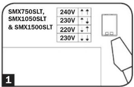
1 With the UPS disconnected from utility power, use a small tool to set the Voltage Dip Switches to match your input voltage. (All models are preset to the 230V setting.)
2 Insert a user-supplied power cord (with country-specific plug) into the UPS System's AC input receptacle. Plug the cord into an AC wall outlet.
NOTE! after you plug the UPS into a live AC outlet, the UPS (in "Standby" mode) will automatically charge its batteries, ^ but will not supply power to its outlets until it is turned ON. ^ The BATTERY CHARGE LED will be the only LED illuminated.
3 Find one of the power cords that came with the UPS. Insert the cord's C13 connector into computer's C14 AC inlet. Insert the cord's C14 plug into any UPS C13 output receptacle.
4 Plug your equipment into the UPS.
Plug your equipment into the UPS. Repeat Step 3 above using the additional power cord(s) that came with the UPS.
Note: Additional power cords (C13 to C14) are available at www.TrippLite.com. Part # P004-006
Your UPS is designed to support computer equipment only. You will overload the UPS if the total VA ratings for all the equipment you connect exceeds UPS output capacity. To find your equipment's VA ratings, look on their nameplates. If the equipment is listed in amps, multiply the number of amps by 240 to determine VA. (Example: 1 amp × 240 = 240 VA). If you are unsure if you have overloaded your UPS's outlets, see "OUTPUT LOAD LEVEL" LED description.
5 Turn the UPS ON.
Press and hold the "ON/OFF/STANDBY" button for one second. The alarm will beep once briefly after one second has passed. Release the button.
Note: UPS system will function properly upon initial startup; however, maximum runtime for the unit's battery will only be accessible after it has been charged for 24 hours.
text_image
SMX750SLT, SMX1050SLT & SMX1500SLT 240V ↑↑ 230V ↑↓ 220V ↓↑ 230V ↓↓ 1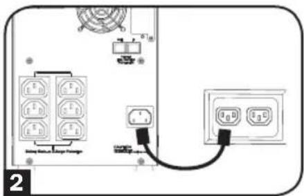
text_image
Diagram showing electrical connections with labeled components and a switch, likely from an industrial or electronic device.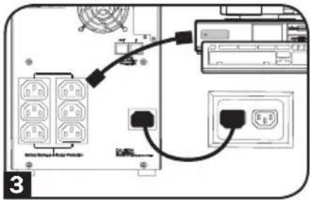
text_image
Diagram showing connection between a device with labeled ports and connections, including a cable or cable connector and a battery terminal.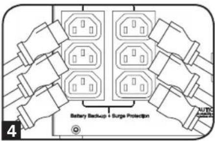
text_image
Battery Backup + Surge Protection AUTIC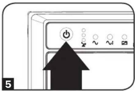
text_image
5Optional Installation
These connections are optional. Your UPS will function properly without these connections.
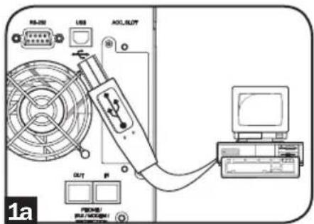
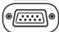
1 USB and RS-232 Serial Communications
Use the included USB cable (see 1a) and/or DB9 serial cable (see 1b) to connect the communication port on your computer to the communication port of your UPS. Install on your computer the Tripp Lite PowerAlert Software appropriate to your computer's operating system.
text_image
RB-201 USB OCL_BLOT OUT PROCH PRO/PROCOM1 1a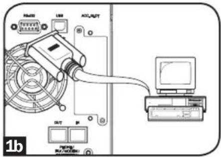
text_image
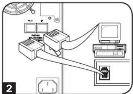
RAM20 USB ACI/AKT OUT P 1b2 Telephone/Network Protection Jacks
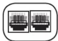
Your UPS has jacks that protect against surges over a telephone line or a network dataline. Using telephone or network data cables, connect your wall jack to the UPS jack marked "IN." Connect your equipment to the UPS jack marked "OUT." Make sure the equipment you connect to the UPS's jacks is also protected against surges on the AC line.
text_image
Diagram showing network connection between computer and printer with labeled ports and cable routingBasic Operation
Buttons (Front Panel)

"ON/OFF/STANDBY" Button
- To turn the UPS ON: with the UPS plugged into a live AC wall outlet*, press and hold the "ON/OFF/STANDBY" button for one second.** Release the button. If utility power is absent, you can "cold-start" the UPS (i.e.: turn it ON and supply power for a limited time from its batteries*** ) by pressing and holding the "ON/OFF/STANDBY" button for one second.**
- To turn the UPS OFF: with the UPS ON and receiving utility power, press and hold the "ON/OFF/STANDBY" button for one second.** Then unplug the UPS from the wall outlet. The UPS will be completely OFF.
* After you plug the UPS into a live AC outlet, the UPS (in "Standby" mode) will automatically charge its batteries, but will not supply power to its outlets until it is turned ON. ** The alarm will beep once briefly after the indicated interval has passed. *** If fully charged.
Basic Operation
"MUTE/TEST" Button
To Silence (or "Mute") UPS Alarms: briefly press and release the MUTE/TEST button.*
To Run a Self-Test: with your UPS plugged in and turned ON, press and hold the MUTE/TEST button. Continue holding the button until the alarm beeps several times and the UPS performs a self test. See “Results of a Self-Test” below.
Note: you can leave connected equipment on during a self-test. Your UPS, however, will not perform a self-test if the UPS is not turned on (see "ON/OFF/STANDBY" Button description).
CAUTION! Do not unplug your UPS to test its batteries. This will remove safe electrical grounding and may introduce a damaging surge into your network connections.
Results of a Self-Test: The test will last approximately 10 seconds as the UPS switches to battery to test its load capacity and battery charge.
- If the “OUTPUT LOAD LEVEL” LED remains lit red and the alarm continues to sound after the test, the UPS’s outlets are overloaded. To clear the overload, unplug some of your equipment and run the self-test repeatedly until the “OUTPUT LOAD LEVEL” LED is no longer lit red and the alarm is no longer sounding.
CAUTION! Any overload that is not corrected by the user immediately following a self-test may cause the UPS to shut down and cease supplying output power in the event of a blackout or brownout.
- If the “BATTERY WARNING” LED remains lit and the alarm continues to sound after the test, the UPS batteries need to be recharged or replaced. Allow the UPS to recharge continuously for 12 hours, and repeat the self-test. If the LED remains lit, contact Tripp Lite for service. If your UPS requires battery placement, visit www.triplite.com/support/battery/index.cfm to locate the specific Tripp Lite replacement battery for your UPS.
* The alarm will beep once briefly after the indicated interval has passed.
Indicator Lights (Front Panel)
All Indicator Light descriptions apply when the UPS is plugged into a wall outlet and turned ON.

"POWER" LED: this green LED lights continuously when the UPS is ON and supplying connected equipment with AC power from a utility source. The LED flashes and an alarm sounds (4 short beeps followed by a pause) to indicate the UPS is operating from its internal batteries during a blackout or severe brownout. If the blackout or severe brownout is prolonged, you should save files and shut down your equipment since internal battery power will eventually be depleted. See "BATTERY CHARGE" LED description below.

"VOLTAGE CORRECTION" LED: this green LED lights continuously whenever the UPS is automatically correcting high or low AC voltage on the utility line without the assistance of battery power. The UPS will also emit a slight clicking noise. These are normal, automatic operations of the UPS, no action is required on your part.
Basic Operation

"OUTPUT LOAD LEVEL" LEDs: the LEDs indicate the approximate electrical load of equipment connected to the UPS's AC outlets. They will turn from green (light load) to yellow (medium load) to red (overload). If the LED is red (either illuminated continuously or flashing), clear the overload immediately by unplugging some of your equipment from the outlets until the LED changes from red to yellow (or green). CAUTION! Any overload that is not corrected by the user immediately may cause the UPS to shut down and cease supplying output power in the event of a blackout or brownout.

"BATTERY CHARGE" LEDs: when the UPS is operating from utility power, the LEDs indicate the approximate charge state of the UPS's internal batteries: red indicates the batteries are beginning to charge; yellow indicates the batteries are roughly midway through charging; and green indicates the batteries are fully charged. When the UPS is operating from battery power during a blackout or severe brownout, the LEDs indicate the approximate amount of energy (ultimately affecting runtime) which the UPS's batteries will provide: red indicates a low level of energy; yellow indicates a medium level of energy; and green indicates a high level of energy. Since the runtime performance of all UPS batteries will gradually deplete over time, it is recommended that you periodically perform a self-test (see MUTE/TEST Button description) to determine the energy level of your UPS batteries BEFORE a blackout or severe brownout occurs. During a prolonged blackout or severe brownout, you should save files and shut down your equipment since battery power will eventually be depleted. When the red LED illuminates and an alarm sounds continuously, it indicates the UPS's batteries are nearly out of power and UPS shutdown is imminent.

"BATTERY WARNING" LED: this LED lights red and an alarm sounds intermittently after you initiate a self test (See "MUTE/TEST" Button description) to indicate the UPS batteries need to be recharged or replaced. Allow the UPS to recharge continuously for 12 hours, and repeat the self-test. If the LED continues to light, contact Tripp Lite for service. If your UPS requires battery replacement, visit www.triplite.com to locate the specific Tripp Lite replacement battery for your UPS.
Other UPS Features (Rear Panel)
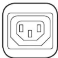
AC Receptacles: Your UPS features IEC-320-C13 outlets. These output receptacles provide your connected equipment with AC line power during normal operation and battery power during blackouts and brownouts. The UPS protects equipment connected to these receptacles against damaging surges and line noise.

Communications Ports (USB or RS-232): These ports connect your UPS to any workstation or server. Use with Tripp Lite's PowerAlert Software and included cables to enable your computer to automatically save open files and shut down equipment during a blackout. Also use PowerAlert Software to monitor a wide variety of AC line power and UPS operating conditions. Consult your PowerAlert Software manual or contact Tripp Lite Customer Support for more information. See “USB and RS-232 Serial Communications” in the “Optional Installation” section for installation instructions.
Telephone/Network Protection Jacks: These jacks protect your equipment against surges over a telephone/network data line. Connecting your equipment to these jacks is optional. Your UPS will work properly without this connection.
Basic Operation
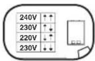
Voltage DIP Switches: These switches enable the UPS to be set to match actual input voltage. If the Voltage DIP Switches are set above or below input voltage, the UPS will treat the input as a continuous overvoltage or undervoltage condition, and will automatically adjust input voltage to match the Voltage DIP Switch setting. This will cause constant, unnecessary wear on the UPS.
Note: The Voltage DIP Switches must be set with the UPS turned OFF and disconnected from utility power. If the switches are set while the UPS is connected to utility power, the setting will not take effect.
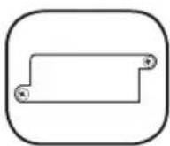
Accessory Slot: Remove the small cover panel from this slot to install optional accessories to remotely monitor and control your UPS. Refer to your accessory's manual for installation instructions. Contact Tripp Lite Customer Support at (773) 869-1234 for more information, including a list of available SNMP, network management and connectivity products.

Input Breaker (SMX1500SLT): Protects your electrical circuit from overcurrent draw from the UPS load. If this breaker trips, remove some of the load, then reset by pressing the breaker in.

Fan: The fan cools the UPS's internal components. It operates only when the UPS is in battery backup mode, is charging its batteries or is carrying a heavy electrical load.
Battery Replacement
Battery Replacement Door: Under normal conditions, the original battery in your UPS will last several years. Battery replacement should be performed only by qualified service personnel. Refer to "Battery Warnings" in the Safety section. Should your UPS require battery replacement, visit Tripp Lite on the Web at www.tripplite.com/support/battery/index.cfm to locate the specific replacement battery for your UPS.
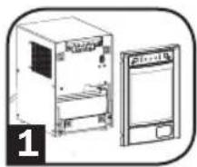
1 Carefully pull the front panel away from the UPS.
Place front panel on top of the unit. Remove the battery support bar.
2 Remove old batteries.
Carefully pull the batteries from the UPS and disconnect them.
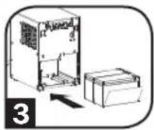
3 Connect new batteries.
Connect the new batteries in exactly the same manner as the old ones: positive (red) connectors together and negative (black) connectors together. Carefully push batteries back into the UPS.
4 Reassemble UPS.
Reinstall the battery support bar and replace the front panel.
natural_image
Illustration of two electronic devices, one with a front panel and the other with a back panel, both without any visible text or symbols.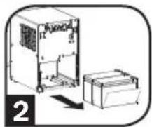
natural_image
Technical line drawing of a mechanical housing and base unit (no text or symbols)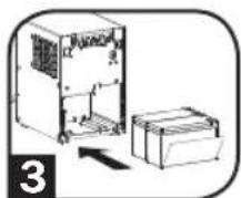
natural_image
Diagram of an electrical enclosure and battery assembly (no text or symbols)Storage and Service
Storage
Before storing your UPS, turn it completely OFF: with the UPS ON and receiving utility power, press and hold the "ON/OFF/STANDBY" button for one second (an alarm will beep once briefly after the interval has passed); then, unplug the UPS from the wall outlet. If you store your UPS for an extended period of time, recharge the UPS batteries once every three months: plug the UPS into a wall outlet; allow it to charge for 12 hours; and then unplug it and place it back in storage. Note: after you plug the UPS in, it will automatically begin charging its batteries; however, it will not supply power to its outlets (see Quick Installation section). If you leave your UPS batteries discharged for an extended period of time, they will suffer a permanent loss of capacity.
Service
A variety of Extended Warranty and On-Site Service Programs are available from Tripp Lite. For more information on service, visit www.tripplite.com/support. Before returning your product for service, follow these steps:
- Review the installation and operation procedures in this manual to insure that the service problem does not originate from a misreading of the instructions.
- If the problem continues, do not contact or return the product to the dealer. Instead, visit www.tripplite.com/support.
- If the problem requires service, visit www.tripplite.com/support and click the Product Returns link. From here you can request a Returned Material Authorization (RMA) number, which is required for service. This simple on-line form will ask for your unit's model and serial numbers, along with other general purchaser information. The RMA number, along with shipping instructions will be emailed to you. Any damages (direct, indirect, special or consequential) to the product incurred during shipment to Tripp Lite or an authorized Tripp Lite service center is not covered under warranty. Products shipped to Tripp Lite or an authorized Tripp Lite service center must have transportation charges prepaid. Mark the RMA number on the outside of the package. If the product is within its warranty period, enclose a copy of your sales receipt. Return the product for service using an insured carrier to the address given to you when you request the RMA.
Regulatory Compliance Identification Numbers
For the purpose of regulatory compliance certifications and identification, your Tripp Lite product has been assigned a unique series number. The series number can be found on the product nameplate label, along with all required approval markings and information. When requesting compliance information for this product, always refer to the series number. The series number should not be confused with the marking name or model number of the product.
Tripp Lite follows a policy of continuous improvement. Product specifications are subject to change without notice.
WEEE Compliance Information for Tripp Lite Customers and Recyclers (European Union)

Under the Waste Electrical and Electronic Equipment (WEEE) Directive and implementing regulations, when customers buy new electrical and electronic equipment from Tripp Lite they are entitled to:
- Send old equipment for recycling on a one-for-one, like-for-like basis (this varies depending on the country)
- Send the new equipment back for recycling when this ultimately becomes waste
Note on Labeling
Two symbols are used on the label.
V\~ : AC Voltage
V = : DC Voltage

text_image
TRIPP·LITE
Manufacturing Excellence.
1111 W. 35th Street, Chicago, IL 60609 USA • www.tripplite.com/support
1111 W. 35th Street, Chicago, IL 60609 USA • www.tripplite.com/support
text_image
Diagram of an electrical control panel with labeled components and connections, including switches and meters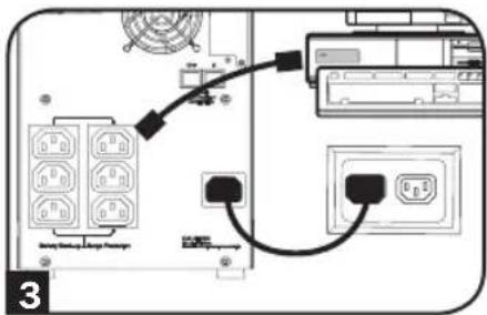
text_image
Diagram showing connection between a device with labeled ports and connectors, including a cable or connector and a control panel.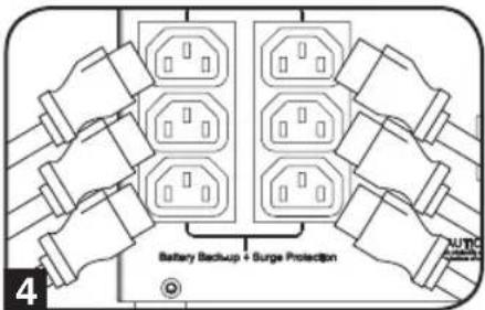
text_image
Battery Backup + Surge Protection 4Instalación rápida
5 Encienda el UPS.
text_image
RAMOS USB ACU/AUT OUT P 1a Piping RUB/ACU/ACU/ACU/ACU/ACU/ACU/ACU/ACU/ACU/ACU/ACU/ACU/ACU/ACU/ACU/ACU/ACU/ACU/ACU/ACU/ACU/ACU/ACU/ACU/ACU/ACU/ACU/ACU/ACU/ACU/ACU/ACU/ACU/ACU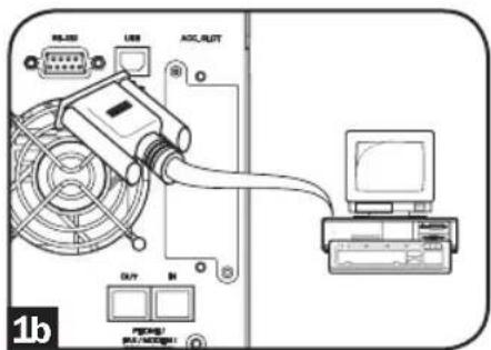
text_image
USB I/O MAX/LUT DAV I/O 1btext_image
Diagram showing network connection between computer and printer with labeled ports and connectionsOperación básica
Botones (Panel frontal)

natural_image
Illustration of two electronic devices, one front view and one side view, with no visible text or symbols.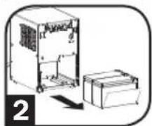
natural_image
Diagram of a mechanical device with a housing and base unit, no visible text or symbols1111 W. 35th Street, Chicago, IL 60609 USA • www.tripplite.com/support
1111 W. 35th Street, Chicago, IL 60609 USA • www.tripplite.com/support
text_image
Diagram showing electrical connections with labeled components and a cable, likely from an industrial or control system.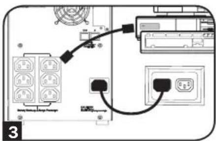
text_image
Diagram showing connection between a device with labeled ports and connectors, including a power outlet and control panel.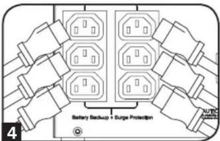
text_image
Battery Backup + Surge Protection AUTO SUGAR PROTECTIONInstallation rapide
natural_image
Illustration of a computer control panel with an arrow pointing to the power button (no text or symbols present)Installation en option
text_image
Diagram showing network connection between computer and printer with labeled ports and cable routingnatural_image
Illustration of two electronic devices, one front view and one side view, with no visible text or symbols.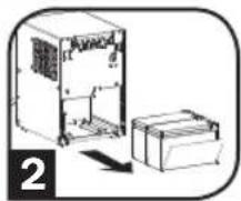
natural_image
Diagram of a device with an open box and a closed box, showing internal components (no text or symbols)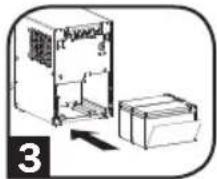
1111 W. 35th Street, Chicago, IL 60609 USA • www.tripplite.com/support
1111 W. 35th Street, Chicago, IL 60609 USA • www.tripplite.com/support
text_image
Diagram showing electrical connections with labeled components and a switch, likely from an electronic device or circuit breaker.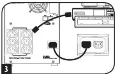
text_image
Diagram showing connection between a device with labeled ports and wiring, including a connector and control panel.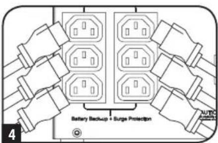
text_image
Battery Backup + Surge Protection AUTO Switch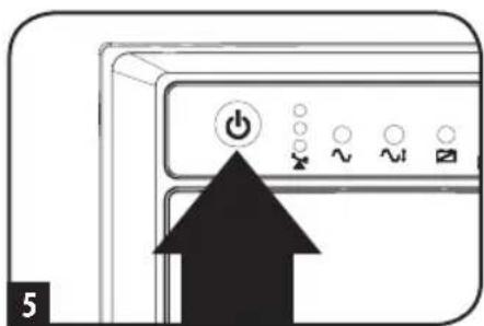
text_image
5text_image
RAMS USB OCL/ACT OUT PROMS/ MULTI/OCT/1text_image
Diagram showing network connection between computer, printer, and network switch with labeled ports and connectionsnatural_image
Illustration of two electronic devices, one with a front panel and the other with a back panel, both enclosed in rounded corners (no text or symbols)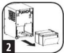
natural_image
Diagram of an electrical enclosure and battery assembly (no text or symbols)
natural_image
Diagram of a refrigerator with an open refrigerator and a box, no text or symbols present1111 W. 35th Street, Chicago, IL 60609 USA • www.tripplite.com/support
Besitzerhandbuch

Manufacturing Excellence.
1111 W. 35th Street, Chicago, IL 60609 USA • www.tripplite.com/support
text_image
Diagram of an electrical control panel with labeled components and connections, including switches and meters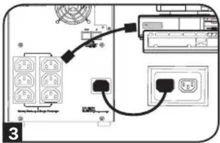
text_image
Diagram showing connection between a device with labeled ports and connectors, including a cable or connector and a battery.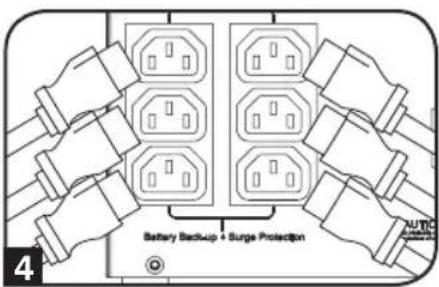
text_image
Battery Backup + Surge Protection 4Installation rapide
natural_image
Close-up of a computer control panel with an arrow pointing to the power button (no text or symbols visible)Optionale Installation
text_image
Diagram showing network connection between computer, printer, and network switch with labeled ports and cable connectionsGrundbetrieb
natural_image
Illustration of two electronic devices, one front view and one side view, with no visible text or symbols.
natural_image
Diagram of a device with an open box and a separate box, no text or symbols present
Manufacturing Excellence
1111 W. 35th Street, Chicago, IL 60609 USA • www.tripplite.com/support