
DMCS70120AMUL - Mobile TV Stand Tripp Lite - Free user manual and instructions
Find the device manual for free DMCS70120AMUL Tripp Lite in PDF.

| Product Type | Mobile screen cart with shelves |
| Brand | Tripp Lite |
| Model | DMCS70120AMUL |
| Intended Use | Indoor only |
| VESA Compatibility | 200x200, 300x200, 300x300, 400x200, 400x300, 400x400, 600x400, 800x400, 800x600, 1000x600 |
| Compatible Screen Type | Flat and curved screens |
| Maximum load per shelf | 5 kg (11 lb) for the AV shelf and video tray |
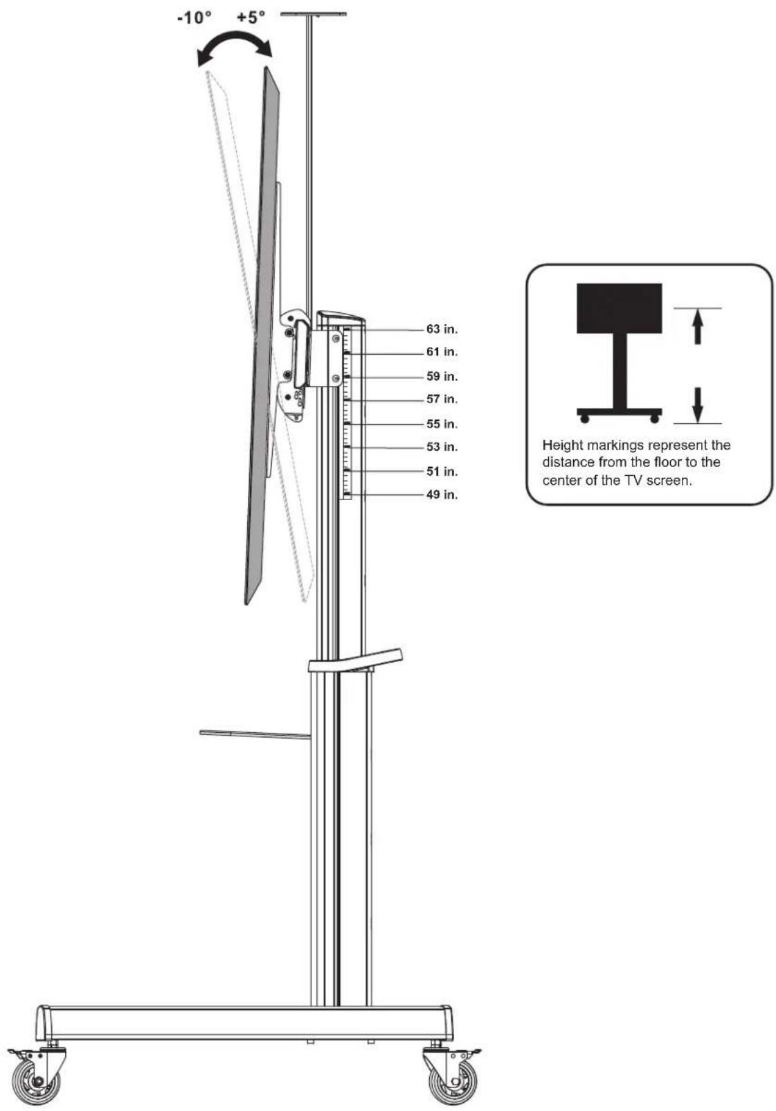
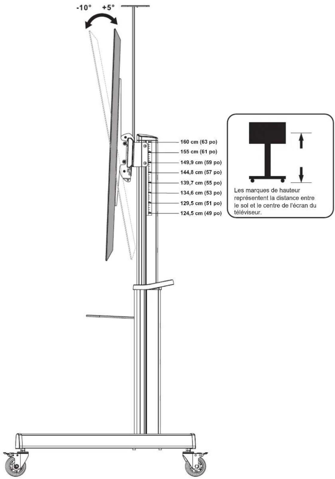
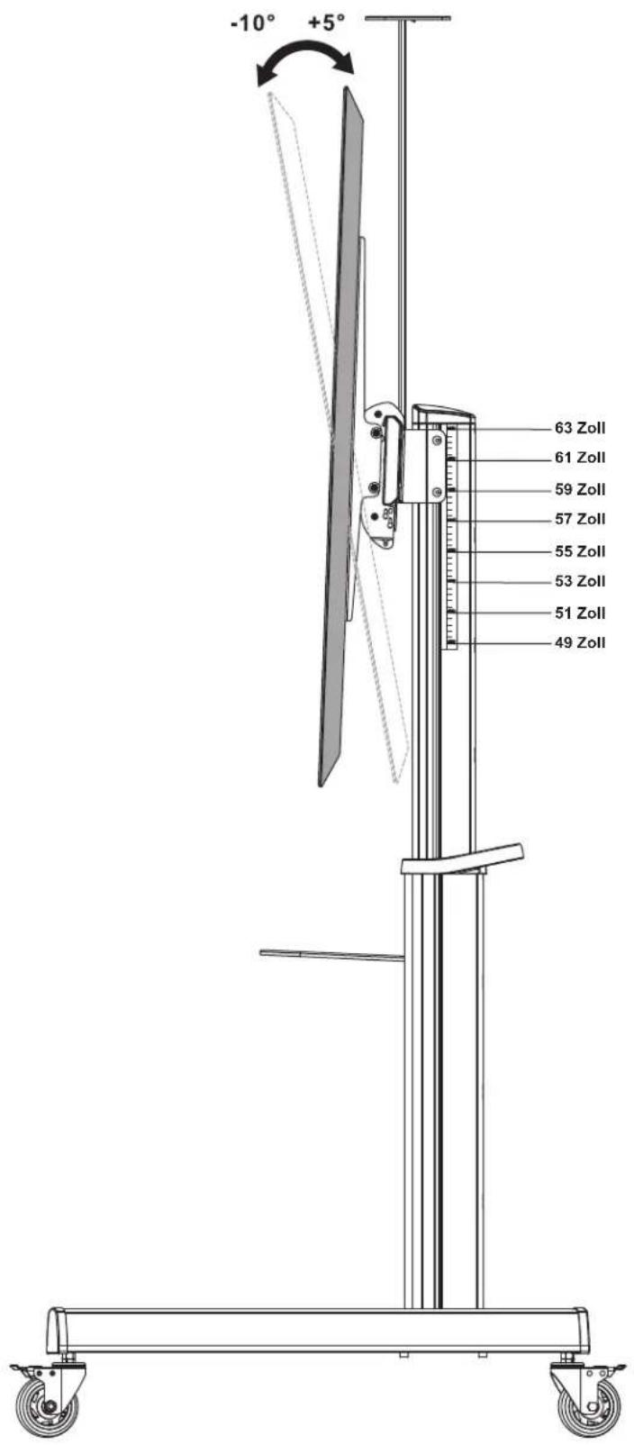
| Adjustable TV Height | Screen center from 124.5 cm to 160 cm from floor |
| Main Material | Steel with antimicrobial coating |
| Certifications | UL |
| Casters | Yes, with brakes |
| Shelves Included | AV shelf, video tray, camera shelf |
| Cable Management | Yes, integrated |
| Screen Tilt | -10° to +5° |
| Anti-theft | Lock slot (lock not included) |
| Warranty | 5-year limited |
| Cleaning | Clean with a soft, dry cloth |
| Country of Origin | Made in China (inferred) |
Frequently Asked Questions - DMCS70120AMUL Tripp Lite
User questions about DMCS70120AMUL Tripp Lite
0 question about this device. Answer the ones you know or ask your own.
Ask a new question about this device
Download the instructions for your Mobile TV Stand in PDF format for free! Find your manual DMCS70120AMUL - Tripp Lite and take your electronic device back in hand. On this page are published all the documents necessary for the use of your device. DMCS70120AMUL by Tripp Lite.
USER MANUAL DMCS70120AMUL Tripp Lite
natural_image
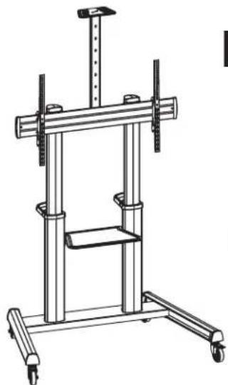
Technical line drawing of a mechanical testing apparatus with vertical supports and wheels (no text or symbols)Super Heavy-Duty Mobile Display Cart with UL Certification & Antimicrobial Protection
Register your product today and be automatically entered to win an ISOBAR® surge protector in our monthly drawing!
tripplite.com/warranty


Manufacturing Excellence.
1111 W. 35th Street, Chicago, IL 60609 USA • tripplite.com/support
Copyright © 2022 Tripp Lite. All rights reserved.
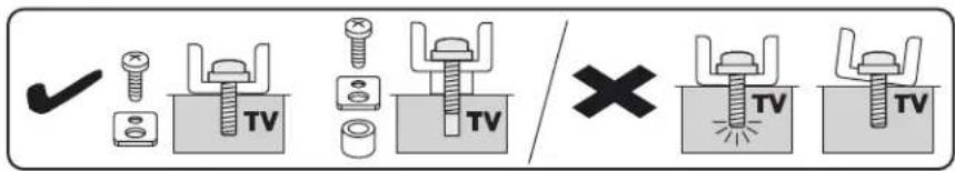
Safety Instructions

WARNING
Do not begin installation until you read and understand the instructions and warnings contained in this manual. If you have any questions regarding any of the instructions or warnings, visit tripplite.com/support.

Death or serious injury may occur when children climb on audio and/or video equipment furniture. A remote control or toys placed on the cart may encourage a child to climb on the cart, causing it to tip over onto the child.

Relocating audio and/or video equipment to furniture not specifically designed to support the audio and/or video equipment may result in death or serious injury caused by the furniture collapsing or turning over onto a child.

Use with equipment heavier than the rated weights indicated may result in instability, causing possible injury.
- Closely follow assembly instructions. Improper installation may result in instability, causing possible injury.
- Safety gear and proper tools must be used. This product should be installed only by qualified professionals.
- Ensure the supporting surface will safely support the combined weight of the equipment and all attached hardware and components.
- Use the mounting screws provided. DO NOT OVERTIGHTEN mounting screws.
- This product contains small items that could be a choking hazard if swallowed. Keep these items away from children.
- This product is intended for indoor use only. Using this product outdoors could lead to product failure and personal injury.
Warranty and Product Registration
5-Year Limited Warranty
Seller warrants this product, if used in accordance with all applicable instructions, to be free from original defects in material and workmanship for a period of 5 years from the date of initial purchase. If the product should prove defective in material or workmanship within that period, Seller will repair or replace the product, in its sole discretion.
THIS WARRANTY DOES NOT APPLY TO NORMAL WEAR OR TO DAMAGE RESULTING FROM ACCIDENT, MISUSE, ABUSE OR NEGLECT. SELLER MAKES NO EXPRESS WARRANTIES OTHER THAN THE WARRANTY EXPRESSLY SET FORTH HEREIN. EXCEPT TO THE EXTENT PROHIBITED BY APPLICABLE LAW, ALL IMPLIED WARRANTIES, INCLUDING ALL WARRANTIES OF MERCHANTABILITY OR FITNESS, ARE LIMITED IN DURATION TO THE WARRANTY PERIOD SET FORTH ABOVE; AND THIS WARRANTY EXPRESSLY EXCLUDES ALL INCIDENTAL AND CONSEQUENTIAL DAMAGES. (Some states do not allow limitations on how long an implied warranty lasts, and some states do not allow the exclusion or limitation of incidental or consequential damages, so the above limitations or exclusions may not apply to you. This warranty gives you specific legal rights, and you may have other rights which vary from jurisdiction to jurisdiction.)
WARNING: The individual user should take care to determine prior to use whether this device is suitable, adequate or safe for the use intended. Since individual applications are subject to great variation, the manufacturer makes no representation or warranty as to the suitability or fitness of these devices for any specific application.
PRODUCT REGISTRATION
Visit tripplite.com/warranty today to register your new Tripp Lite product. You'll be automatically entered into a drawing for a chance to win a FREE Tripp Lite product!*
* No purchase necessary. Void where prohibited. Some restrictions apply. See website for details.
Tripp Lite has a policy of continuous improvement. Specifications are subject to change without notice. Photos and illustrations may differ slightly from actual products.
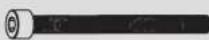
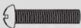
Component Checklist
IMPORTANT: Ensure you have received all parts according to the component checklist prior to installing. If any parts are missing or faulty, visit tripplite.com/support for service.
Package P


P-F
Spacer (x1)
P-G
M6 Wrench (x1)
P-H
M12 Wrench (x1)
P-1
5mm Allen Key
(x1)
P-J
6mm Allen Key
(x1)
P-A
Washer (x8)
P-B
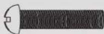
M8x80 (x8)
P-C
M8x20
(x12)
P-D
M5x8 (x2)
P-E
M8x12 (x2)
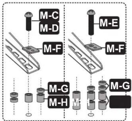
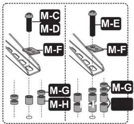
Package M

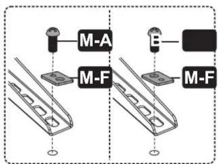
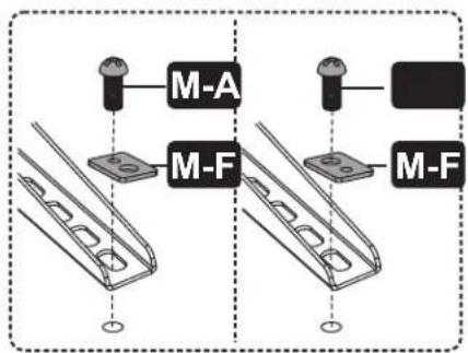
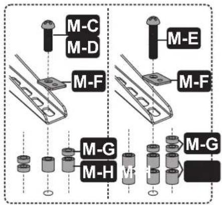
M-A
M5x14 (x4)

M-B
M6x14 (x4)
M-C
M6x30 (x4)
M-D
M8x30 (x4)
M-E
M8x50 (x4)
M-F
Washer (x4)

M-G
Small
Spacer (x8)

M-H
Big Spacer (x8)
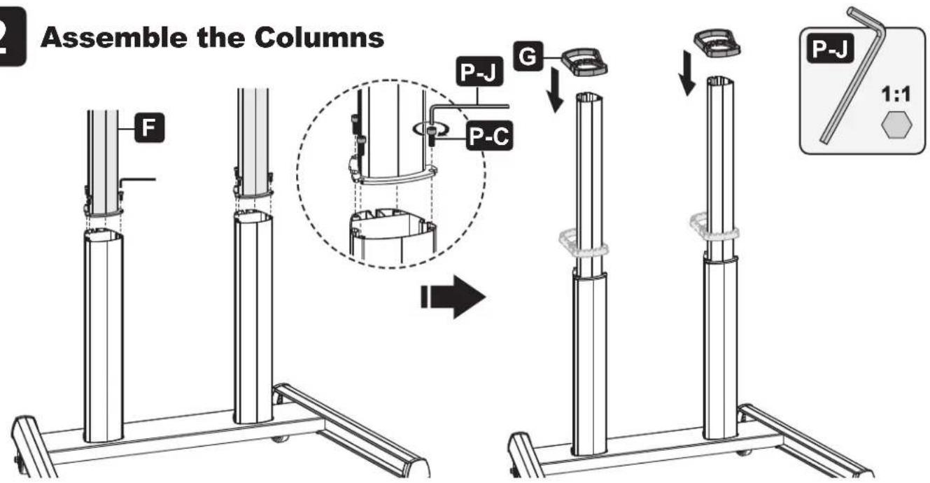
Assembly
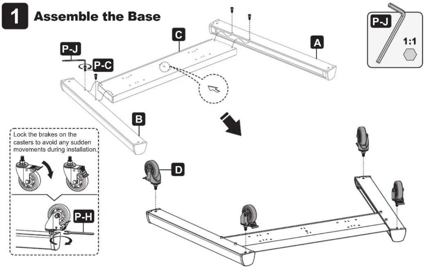
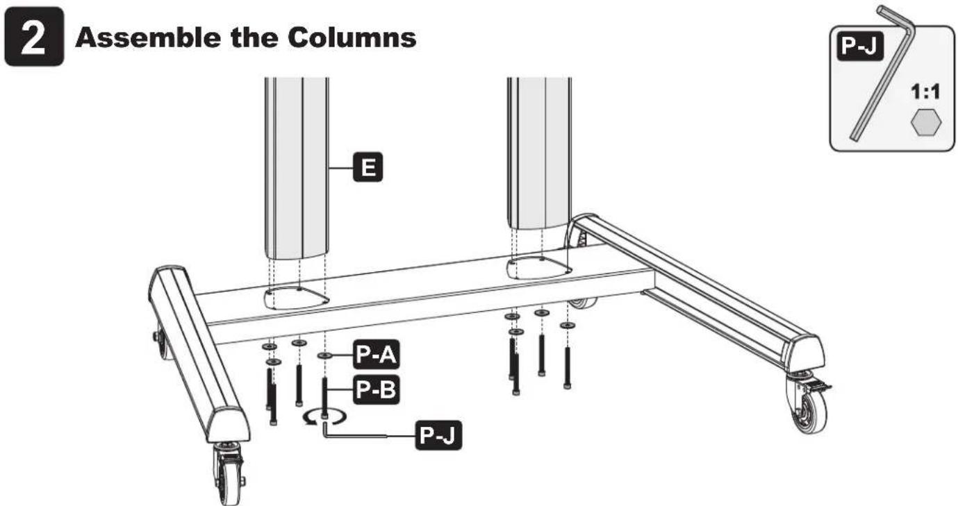
Assembly
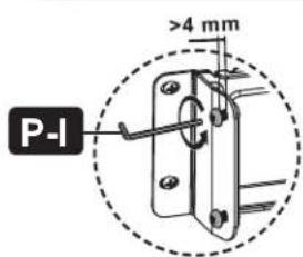
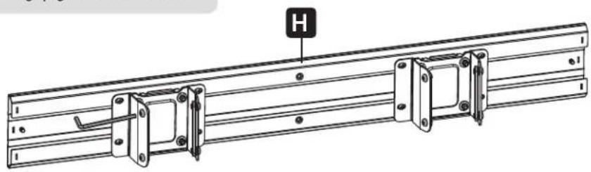
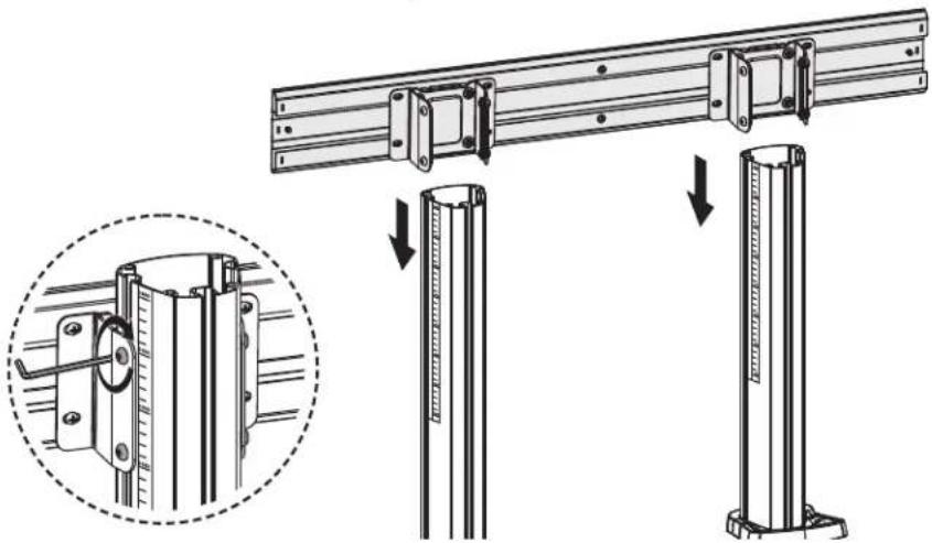
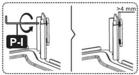
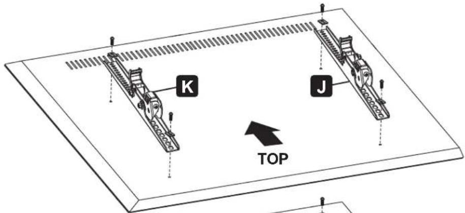
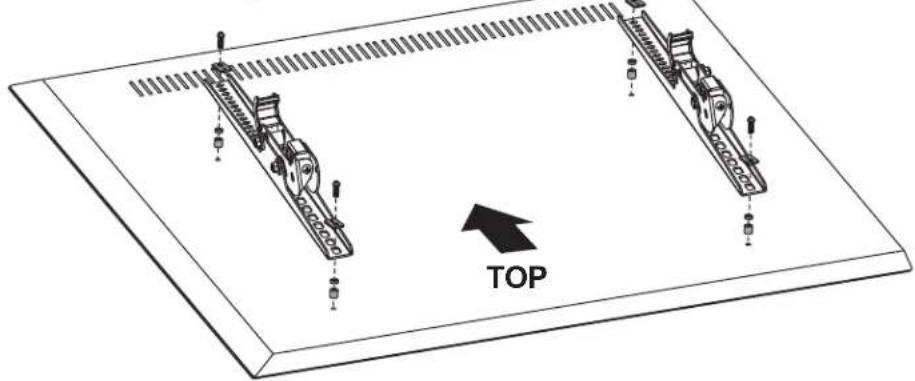
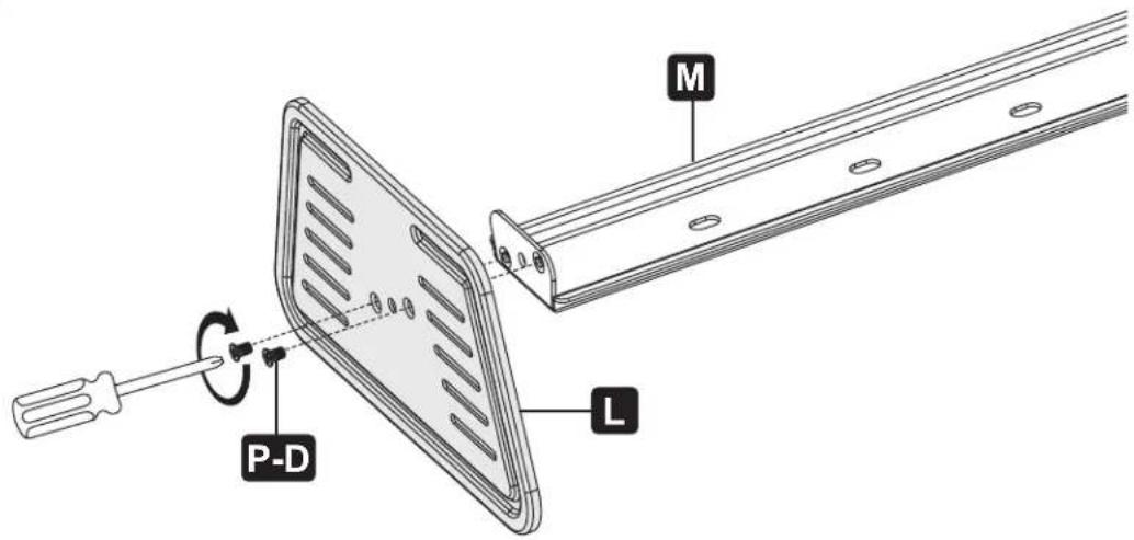
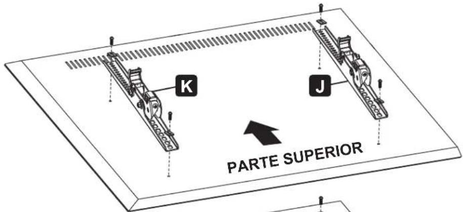
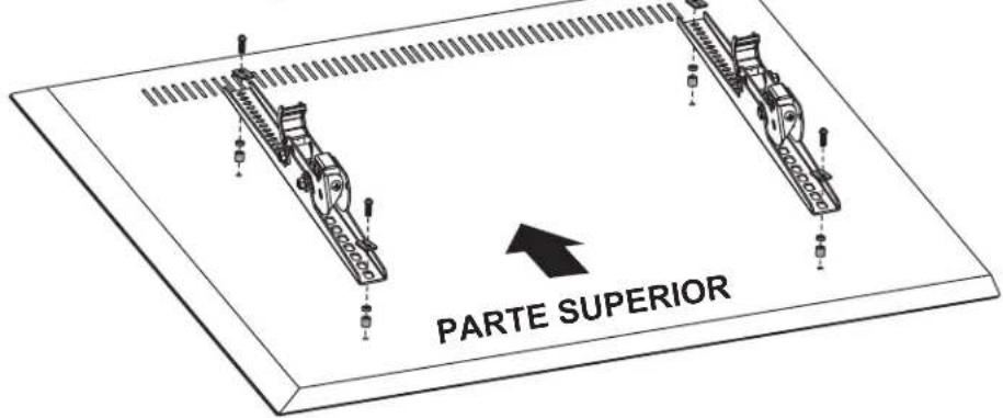
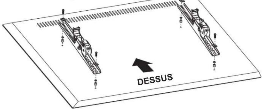
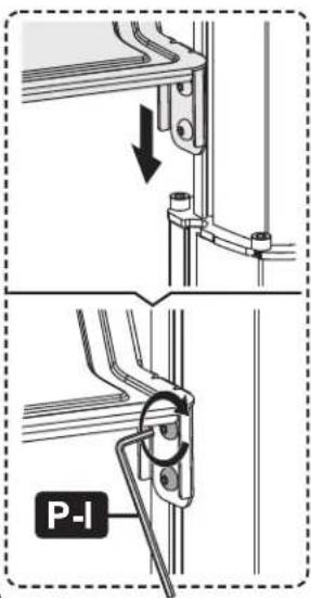
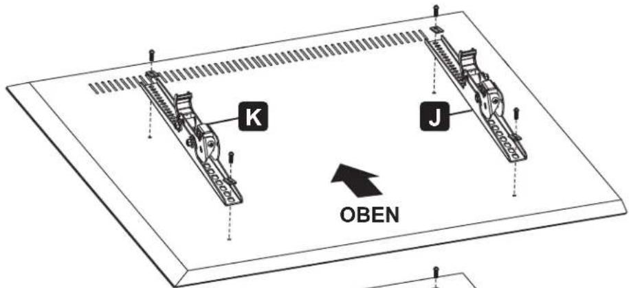
3 Attach the Mounting Plate to the Column
Loosen the screws to leave a gap greater than 4 mm.
natural_image
Technical line drawing of a mechanical rail assembly with mounting brackets and a labeled component 'H' (no text or symbols beyond label)
natural_image
Technical illustration of a mechanical rail assembly with mounting brackets and structural supports, showing a close-up of a component (no text or symbols present)Assembly
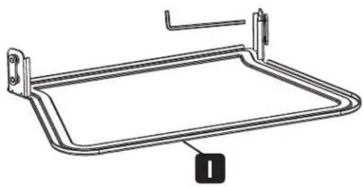
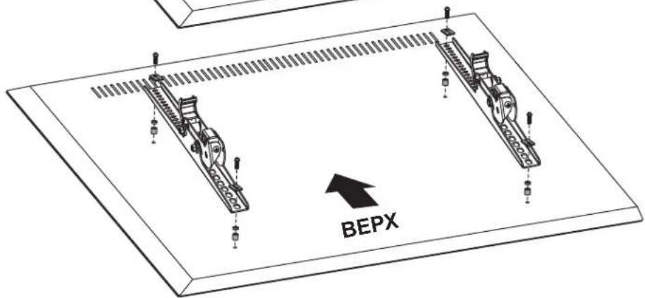
4 Assemble the AV Equipment Shelf
Loosen the screws to leave a gap greater than 4 mm.
natural_image
Technical line drawing of a rectangular metal frame with mounting brackets (no text or symbols)
natural_image
Technical line drawing of a mechanical lifting frame with wheels and structural supports (no text or symbols)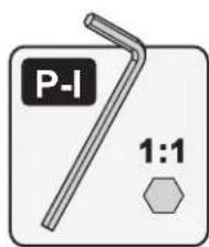

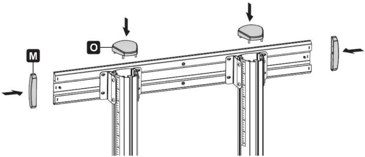
5 Assemble the Top Covers and End Caps
Assembly
6
Attach the TV Bracket to the Back of a Flat or Curved Screen


natural_image
Technical diagram of two mechanical components with a directional arrow labeled 'TOP' pointing to them (no text or symbols on the components themselves)
Assembly
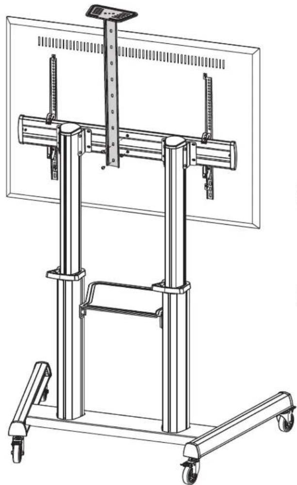
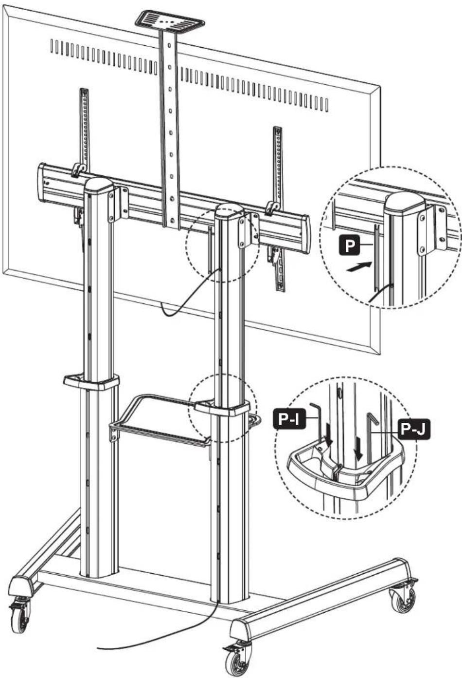
7 Hang and Secure the Screen
natural_image
Illustration of a screwdriver with a plus button symbol (no text or labels)
natural_image
Technical line drawing of a mechanical lifting device with a magnified inset showing the assembly process (no text or symbols present)
natural_image
Three-step diagram showing a screwdriver inserted into a bracket, with no text or symbols present.
natural_image
Technical line drawing of a mechanical support frame with wheels and vertical supports (no text or symbols)- Turn the bottom screw counterclockwise to tighten it.
- Turn the bottom screw clockwise to loosen it.
- Use a padlock (not included) to prevent theft of the display.
IMPORTANT: Ensure the display is correctly mounted before releasing the display.
Assembly
8
Assemble the Camera Shelf
natural_image
Technical line drawing of a mechanical support system with vertical supports and wheels (no text or symbols)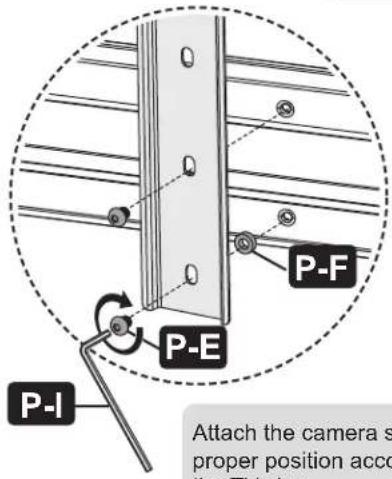
Attach the camera shelf to proper position according to the TV size.
Assembly
9 Cable Management
Adjustment
Troubleshooting
If the columns are not properly aligned, the mouting plate may fail to attach to the columns. Follow the steps below to re-assemble the columns.
Maintenance
- Check that the bracket is secure and safe to use at regular intervals (at least every three months).
- For any additional questions, visit tripplite.com/support.

1111 W. 35th Street, Chicago, IL 60609 USA • tripplite.com/support
21-11-027 9340ED_RevA
natural_image
Technical line drawing of a mechanical lifting device with vertical supports and wheels (no text or symbols)natural_image
Technical line drawing of a mechanical rail assembly with mounting brackets and a labeled component 'H' (no text or symbols beyond label)

natural_image
Technical illustration of a mechanical rail assembly with mounting brackets and structural supports, showing a close-up of a component (no text or symbols present)Ensamble
natural_image
Technical line drawing of a rectangular metal frame with mounting brackets (no text or symbols)
natural_image
Technical line drawing of a mechanical lifting frame with wheels and structural supports (no text or symbols)

Ensamble


Ensamble
natural_image
Illustration of a screwdriver with a plus button symbol (no text or labels)
natural_image
Technical line drawing of a mechanical lifting device with a close-up inset showing the assembly process (no text or symbols present)
natural_image
Three-step diagram showing a screwdriver inserted into a bracket, with no text or symbols present.
natural_image
Technical line drawing of a mechanical support frame with wheels and vertical supports (no text or symbols)natural_image
Technical line drawing of a mechanical lifting device with wheels and vertical supports (no text or symbols)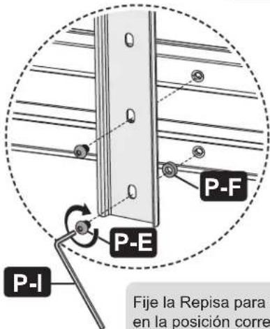
Ajuste
![-10° +5° 160 cm [63"] 155 cm [61"] 150 cm [59"] 145 cm [57"] 140 cm [55"] 135 cm [53"] 130 cm [51"] 125 cm [49"] Las marcas de altura representan la distancia desde el piso hasta el centro de la pantalla de TV.](/content/2026/04/585306/images/f975f2342760dd793fac981dd368ede99d3d3cd2a1ddfb63d74d0ca167bd899a.jpg)
Mantenimiento
natural_image
Technical line drawing of a mechanical testing apparatus with vertical supports and wheels (no text or symbols)1111 W. 35th Street, Chicago, IL 60609 USA • tripplite.com/support
natural_image
Technical line drawing of a mechanical rail assembly with mounting brackets and a labeled component 'H' (no text or symbols beyond label)

natural_image
Technical diagram showing mechanical assembly with a bracket and mounting base, including a close-up inset of a component detail (no text or symbols)Assemblage
natural_image
Technical line drawing of a rectangular metal frame with mounting brackets (no text or symbols)
natural_image
Technical line drawing of a mechanical lifting frame with wheels and structural supports (no text or symbols)
Assemblage


Assemblage
natural_image
Illustration of a screwdriver with a plus button symbol (no text or labels)
natural_image
Technical line drawing of a mechanical lift assembly with mounting bracket and side view (no text or symbols)
natural_image
Three-step diagram showing a screwdriver inserted into a bracket, with no text or symbols present.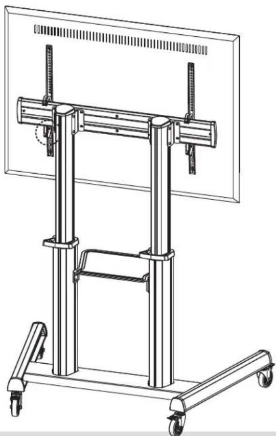
natural_image
Technical line drawing of a mechanical support frame with wheels and vertical supports (no text or symbols)natural_image
Technical line drawing of a mechanical support system with vertical supports and wheels (no text or symbols)
Réglage
Entretien
natural_image
Technical line drawing of a mechanical testing apparatus with no visible text or symbolsПередвижная
1111 W. 35th Street, Chicago, IL 60609 USA • tripplite.com/support
natural_image
Technical line drawing of a mechanical rail assembly with mounting brackets and a labeled component 'H' (no text or symbols beyond label)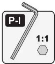

natural_image
Technical illustration of a mechanical rail assembly with mounting brackets and structural supports, showing a close-up of a component (no text or symbols present)Порядок сборки
natural_image
Technical line drawing of a rectangular metal frame with mounting brackets (no text or symbols)
natural_image
Technical line drawing of a mechanical lifting frame with wheels and structural supports (no text or symbols)
Порядок сборки

Порядок сборки
natural_image
Illustration of a screwdriver with a plus button symbol (no text or labels)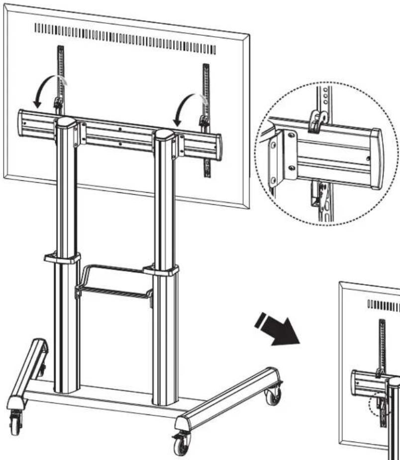
natural_image
Technical line drawing of a mechanical lifting device with a magnified inset showing the assembly process (no text or symbols present)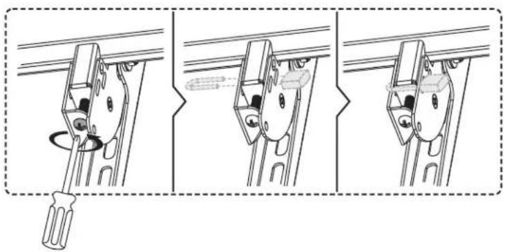
natural_image
Three-step diagram showing a screwdriver inserted into a bracket, with no text or symbols present.
natural_image
Technical line drawing of a mechanical support frame with wheels and vertical supports (no text or symbols)natural_image
Technical line drawing of a mechanical lifting device with wheels and vertical supports (no text or symbols)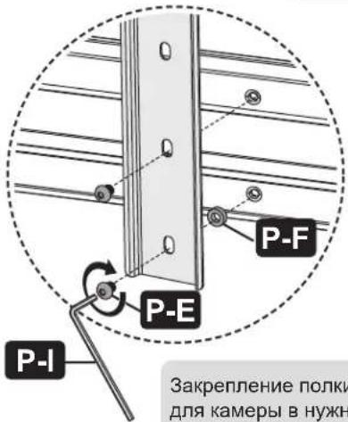
1111 W. 35th Street, Chicago, IL 60609 USA • tripplite.com/support
21-11-027 9340ED RevA
Bedienungsanleitung
natural_image
Technical line drawing of a mechanical testing apparatus with vertical supports and wheels (no text or symbols)1111 W. 35th Street, Chicago, IL 60609 USA • tripplite.com/support
natural_image
Technical illustration of a mechanical rail assembly with mounting brackets and structural supports, showing a close-up of the component (no text or symbols present)Montage
natural_image
Technical line drawing of a rectangular metal frame with mounting brackets (no text or symbols)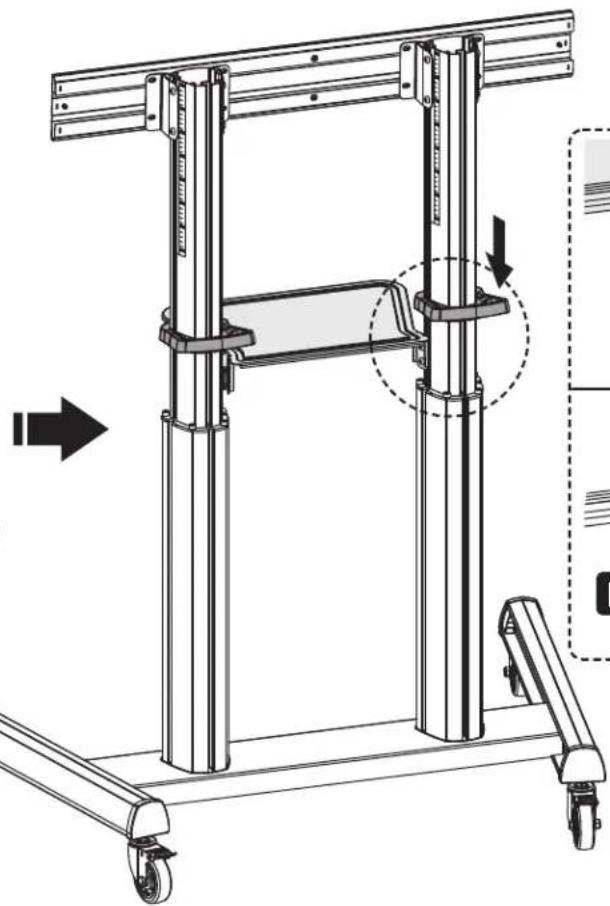
natural_image
Technical line drawing of a mechanical lifting frame with wheels and structural supports (no text or symbols)

Montage

Montage
natural_image
Illustration of a screwdriver with a plus button symbol (no text or labels)
natural_image
Technical line drawing of a mechanical lifting device with a close-up inset showing the assembly process (no text or symbols present)
natural_image
Three-step diagram showing a screwdriver inserted into a bracket, with no text or symbols present.
natural_image
Technical line drawing of a mechanical support frame with wheels and vertical supports (no text or symbols)natural_image
Technical line drawing of a mechanical support system with vertical supports and wheels (no text or symbols)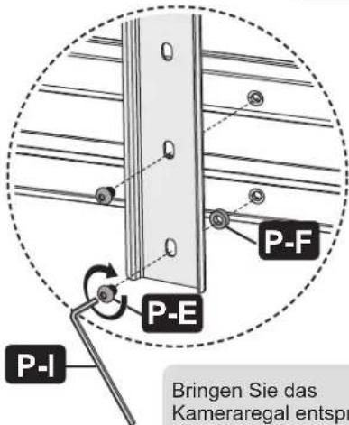
Einstellung
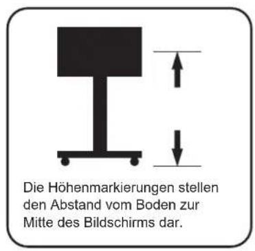
Wartung

Manufacturing Excellence.
1111 W. 35th Street, Chicago, IL 60609 USA • tripplite.com/support
21-11-027 9340ED_RevA
- Super Heavy-Duty Mobile Display Cart with UL Certification & Antimicrobial Protection
- Safety Instructions
- WARNING
- Warranty and Product Registration
- 5-Year Limited Warranty
- PRODUCT REGISTRATION
- Component Checklist
- Assembly
- Assemble the AV Equipment Shelf
- Assemble the Top Covers and End Caps
- Hang and Secure the Screen
- 8
- Assemble the Camera Shelf
- Cable Management
- Adjustment
- Troubleshooting
- Maintenance
- Ensamble
- Ajuste
- Mantenimiento
- Assemblage
- Réglage
- Entretien
- Передвижная
- Порядок сборки
- Bedienungsanleitung
- Montage
- Einstellung
- Wartung
Brand : Tripp Lite
Model : DMCS70120AMUL
Category : Mobile TV Stand