
DMCS60100XXCK - TV Mount Tripp Lite - Free user manual and instructions
Find the device manual for free DMCS60100XXCK Tripp Lite in PDF.

| Product Type | Mobile TV Stand on Wheels |
| Brand | Tripp Lite |
| Model | DMCS60100XXCK |
| Maximum Load Capacity | Approximately 100 kg |
| Compatible Screen Size | 60 to 100 inches |
| Height Adjustment | Yes, via hand crank |
| Casters | 4 swivel casters with lockable brakes |
| Main Material | Sturdy Steel |
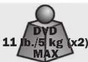
| Included Shelves | Two DVD shelves (upper and lower) and one camera shelf |
| Anti-theft Security | Compatibility with a padlock (not included) to lock the screen |
| Warranty | 5 years |
| Intended Use | Indoor only |
| Approximate Dimensions (H x W x D) | 150 to 180 cm x 80 cm x 60 cm (height adjustable) |
| Approximate Weight | 30 kg |
| Included Accessories | Crank, hex keys, 19 mm wrench, screws, washers, spacers |
| Assembly Required | Yes, with tools provided |
| Power Supply | None (manual operation) |
| Maintenance and Cleaning | Regularly check screw tightness and stability; clean with a dry cloth |
| Spare Parts and Repairability | Parts available through Tripp Lite support |
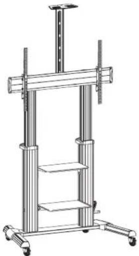
| General Information | Sturdy wheeled cart with telescopic column and crank for easy height adjustment |
Frequently Asked Questions - DMCS60100XXCK Tripp Lite
User questions about DMCS60100XXCK Tripp Lite
0 question about this device. Answer the ones you know or ask your own.
Ask a new question about this device
Download the instructions for your TV Mount in PDF format for free! Find your manual DMCS60100XXCK - Tripp Lite and take your electronic device back in hand. On this page are published all the documents necessary for the use of your device. DMCS60100XXCK by Tripp Lite.
USER MANUAL DMCS60100XXCK Tripp Lite
Heavy-Duty Rolling TV/Monitor Cart with Crank Handle
Model: DMCS60100XXCK
Español 12 • Français 23 • Русский 34 • Deutsch 45

CAUTION: DO NOT EXCEED MAXIMUM LISTED WEIGHT CAPACITY. SERIOUS INJURY OR PROPERTY DAMAGE MAY OCCUR!

200 × 200 / 300 × 300
400 x 200 / 400 x 400
600 x 400 / 800 x 400
800×600/1000×600


WARRANTY REGISTRATION
Register your product today and be automatically entered to win an ISOBAR ® surge protector in our monthly drawing!
tripplite.com/warranty


1111 W. 35th Street, Chicago, IL 60609 USA • tripplite.com/support
Copyright © 2021 Tripp Lite. All rights reserved.
Safety Instructions
NOTE: Read the entire Owner's Manual before you start installation and assembly.

WARNING
- Do not begin the installation until you have read and understood the instructions and warnings contained in this manual. If you have any questions regarding any of the instructions or warnings, please visit tripplite.com/support.
- This mounting bracket was designed to be installed and utilized ONLY as specified in this manual. Improper installation of this product may cause damage or serious injury.
- This product should only be installed by someone of good mechanical ability, with basic building experience and a full understanding of this instruction manual.
- Make sure that the mounting surface can safely support the combined load of the equipment and all attached hardware and components.
- If mounting to wood wall studs, make sure that mounting screws are anchored into the center of the studs. The use of a stud finder is highly recommended.
• Always use an assistant or mechanical lifting equipment to safely lift and position equipment. - Tighten screws firmly, but do not over-tighten. Over-tightening screws can damage the items, greatly reducing their holding power.
- This product is intended for indoor use only. Using this product outdoors could lead to product failure and personal injury.
Warranty and Product Registration
5-Year Limited Warranty
Seller warrants this product, if used in accordance with all applicable instructions, to be free from original defects in material and workmanship for a period of 5 years from the date of initial purchase. If the product should prove defective in material or workmanship within that period, Seller will repair or replace the product, in its sole discretion.
THIS WARRANTY DOES NOT APPLY TO NORMAL WEAR OR TO DAMAGE RESULTING FROM ACCIDENT, MISUSE, ABUSE OR NEGLECT. SELLER MAKES NO EXPRESS WARRANTIES OTHER THAN THE WARRANTY EXPRESSLY SET FORTH HEREIN. EXCEPT TO THE EXTENT PROHIBITED BY APPLICABLE LAW, ALL IMPLIED WARRANTIES, INCLUDING ALL WARRANTIES OF MERCHANTABILITY OR FITNESS, ARE LIMITED IN DURATION TO THE WARRANTY PERIOD SET FORTH ABOVE; AND THIS WARRANTY EXPRESSLY EXCLUDES ALL INCIDENTAL AND CONSEQUENTIAL DAMAGES. (Some states do not allow limitations on how long an implied warranty lasts, and some states do not allow the exclusion or limitation of incidental or consequential damages, so the above limitations or exclusions may not apply to you. This warranty gives you specific legal rights, and you may have other rights, which vary from jurisdiction to jurisdiction).
WARNING: The individual user should take care to determine prior to use whether this device is suitable, adequate or safe for the use intended. Since individual applications are subject to great variation, the manufacturer makes no representation or warranty as to the suitability or fitness of these devices for any specific application.
PRODUCT REGISTRATION
Visit tripplite.com/warranty today to register your new Tripp Lite product. You'll be automatically entered into a drawing for a chance to win a FREE Tripp Lite product!*
* No purchase necessary. Void where prohibited. Some restrictions apply. See website for details.
Tripp Lite has a policy of continuous improvement. Specifications are subject to change without notice. Photos and illustrations may differ slightly from actual products.
Component Checklist
IMPORTANT: Ensure you have received all parts according to the component checklist prior to installing. If any parts are missing or faulty, visit tripplite.com/support for service.
A
Middle Base (x1)
B
Left Leg (x1)
C
Right Leg (x1)

D
Left Cover (x1)
E
F
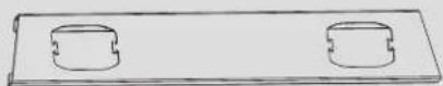
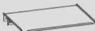
Universal Plate (x1)

G
Plastic Cover (x2)

H
Plastic Handle (x2)
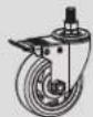
I
Caster (x4)
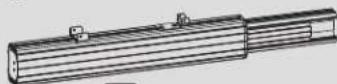
J
Left Column (x1)
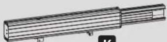
K
Right Column (x1)
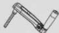
L
Crank Handle (x1)

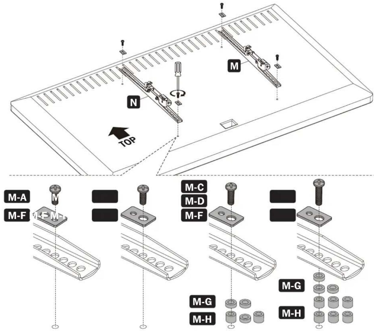
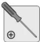
M
Left Adapter Bracket (x1)

N
Right Adapter Bracket (x1)

0
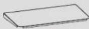
Top Cover (x1)

P
Camera Shelf (x1)
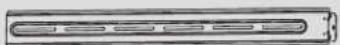
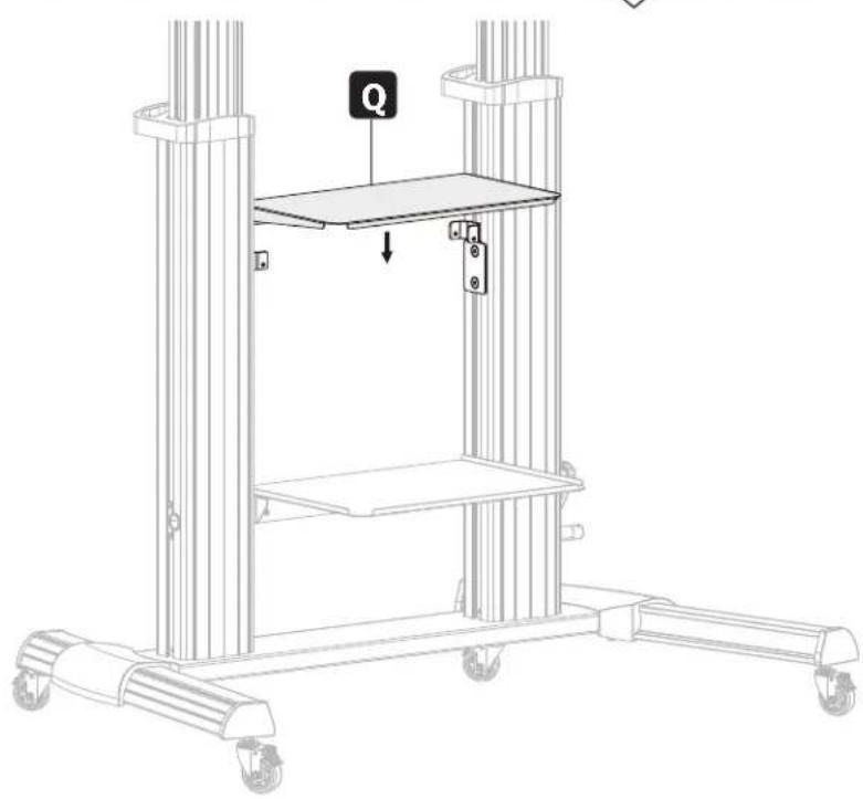
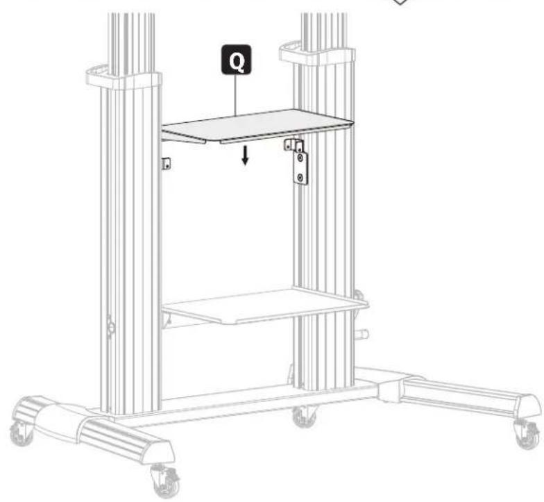
Q
Upper DVD Shelf (x1)
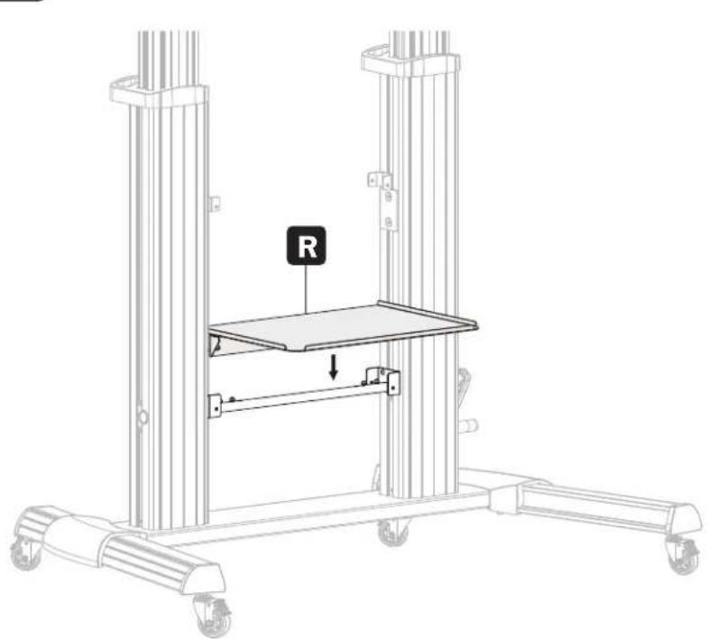
R
Lower DVD Shelf (x1)
S
Connecting Plate (x1)
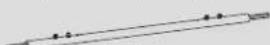
T
Connecting Bar (x1)
Package P

U
M5x40 (x1)

V
M6x25 (x4)

W
M4x6 (x3)

X
M4x6 (x3)

Y
M6x14 (x4)

Z
M8x25 (x12)

A1
M6x8 (x12)

B1
5 mm Hex Key(x1)

C1
19 mm Wrench (x1)
Package M

M-A
M5x14 (x4)

M-B
M6x14 (x4)
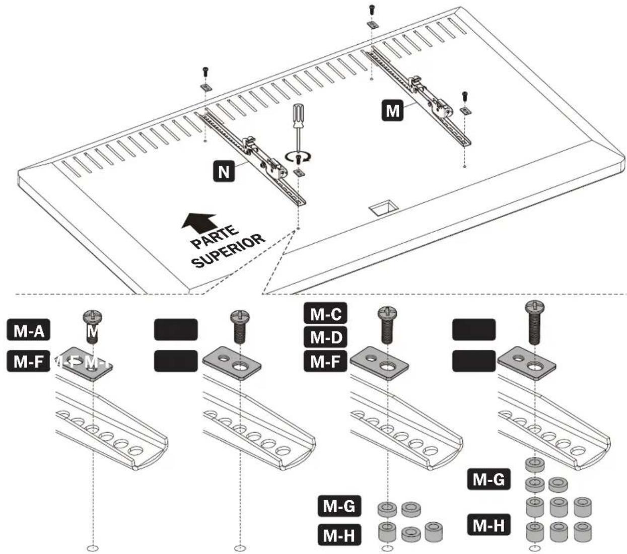
M-C
M6x30 (x4)
M-D
M8x30 (x4)
M-E
M8x50 (x4)

M-F
D5-D8 (x4)

M-G
∅15x∅8x5 (x8)

M-H
∅15x∅8x15 (x8)
Assembly
1
2

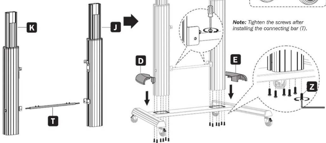
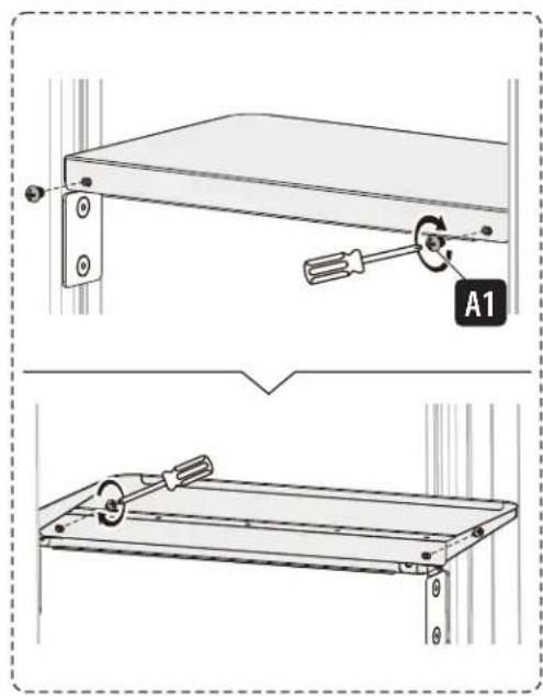
CAUTION: Hold the inner column when loosening screws to adjust height. Adjust to the desired height, then tighten the screws, leaving a small gap between screws (Z) and the outer columns. Also, make sure the left and right inner columns are at the same height.
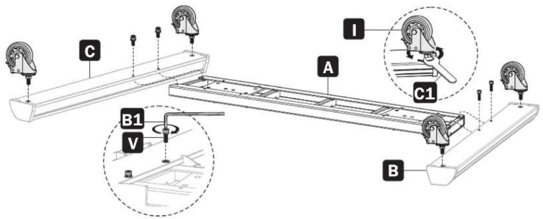
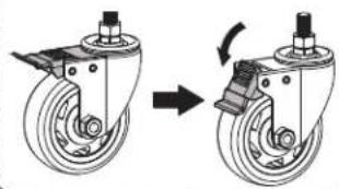
Install the heavy-duty locking casters into the threaded caster slots. Use the wrench (C1) to tighten the casters.
Note: Tighten the screws after installing the connecting bar (T).
Assembly
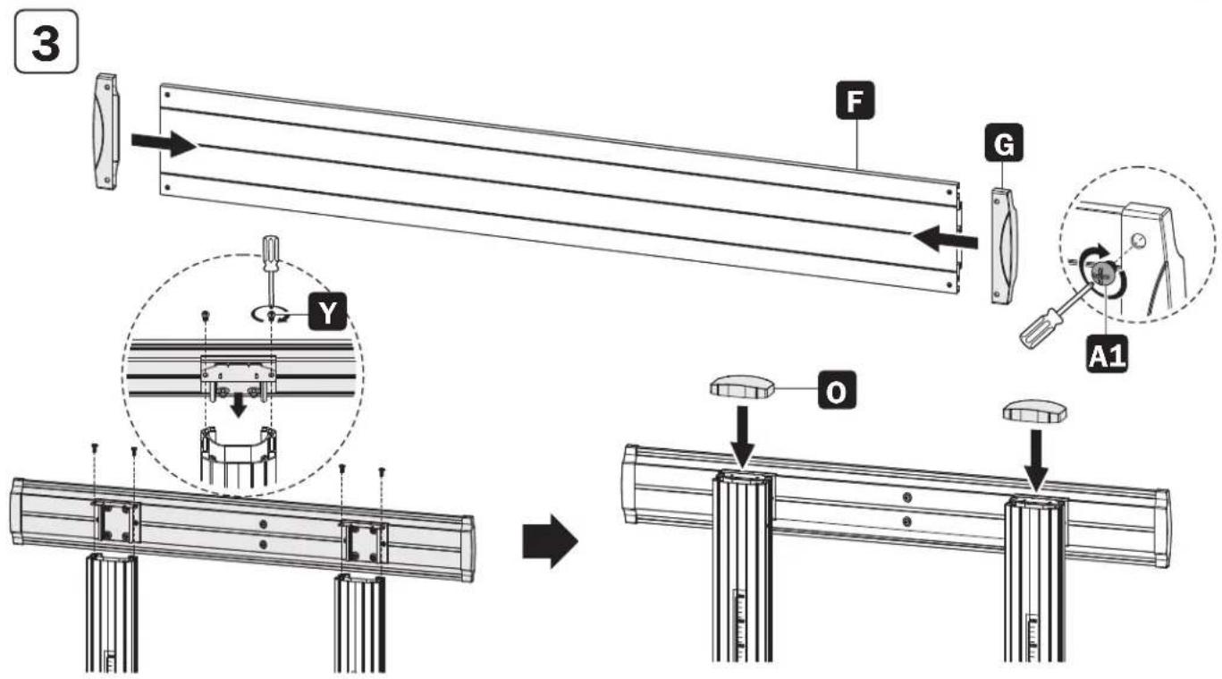

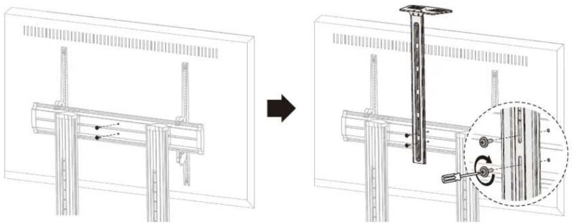
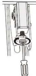
CAUTION: After assembling the universal plate (F) to the columns as shown, tighten the screws (Z).

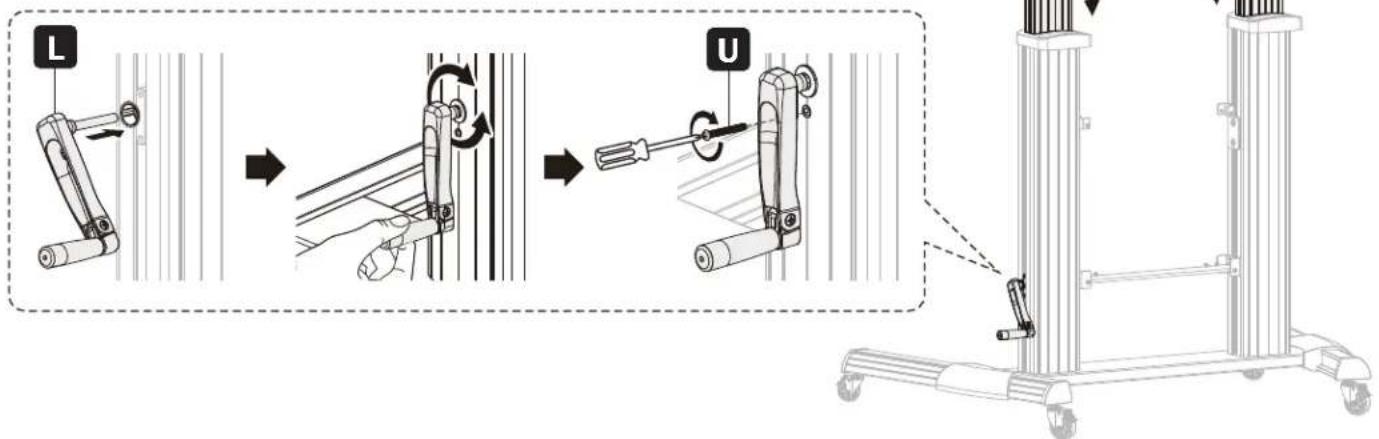
Note: Adjust the height with the crank handle (L), then tighten the screw (U).
Assembly
5


Assembly
6
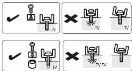
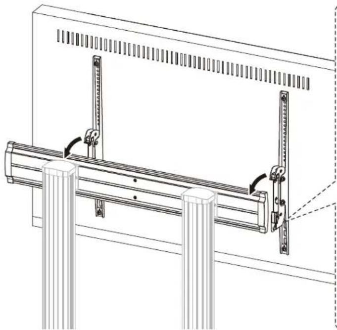
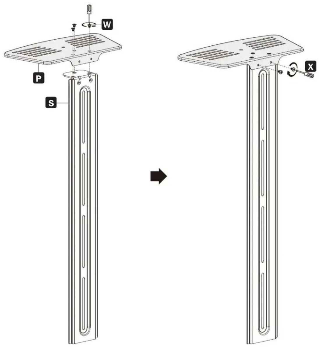
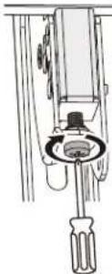
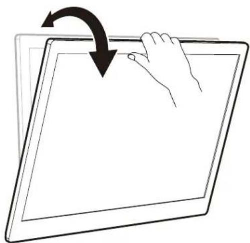
Note: Choose the appropriate screws, washers and spacers (if needed) according to the type of screen. Screw the adapter brackets onto the display.

CAUTION: Tighten all screws but do not over tighten.

Assembly
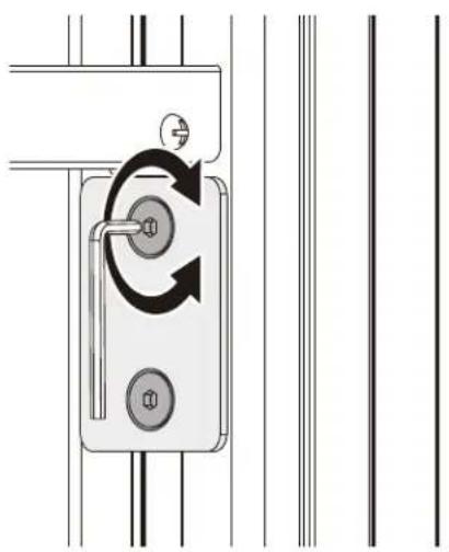
7


Notes:
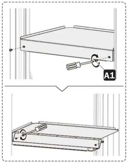
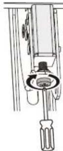
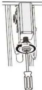
• To lock, rotate the bottom screws counterclockwise.
• To unlock, rotate the bottom screws clockwise.
Note: Use a padlock (not included) to protect the display from tampering or theft.
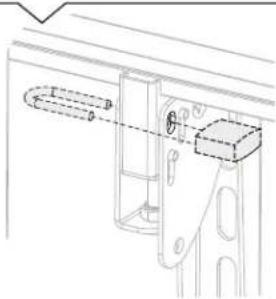

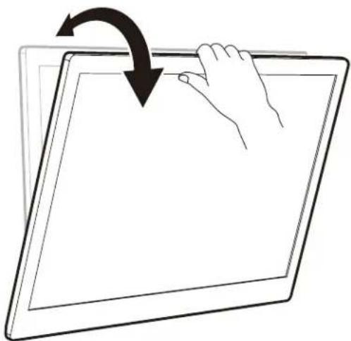
CAUTION: Be sure the display is correctly mounted and the screws are securely tightened before releasing the display.
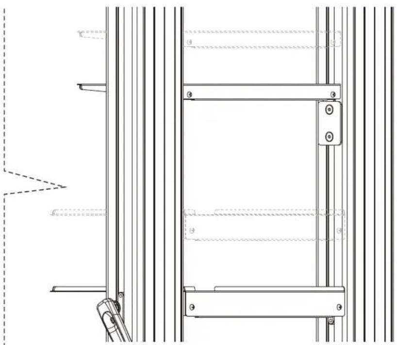
Assembly
8

Adjustment

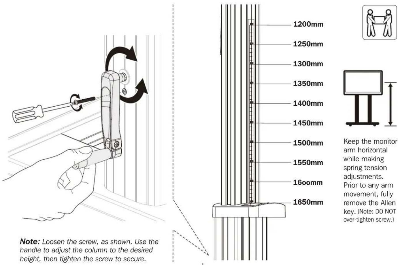
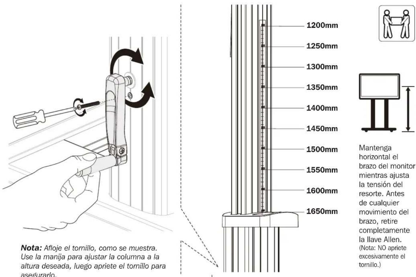
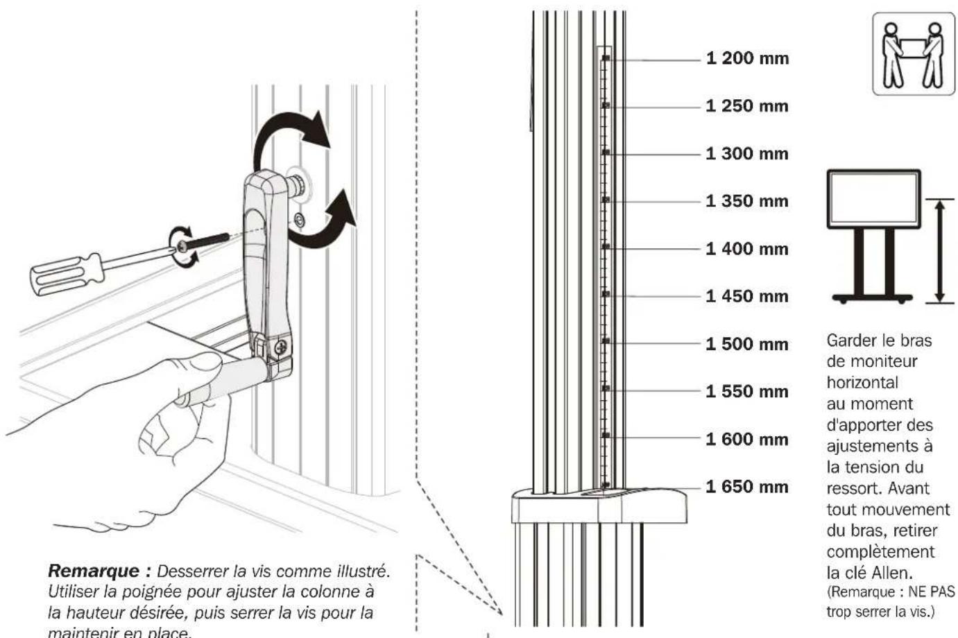
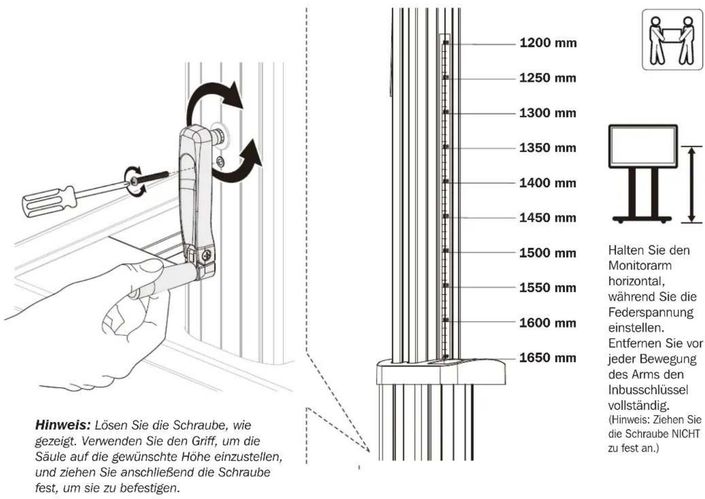
Note: Loosen the screw, as shown. Use the handle to adjust the column to the desired height, then tighten the screw to secure.
Keep the monitor arm horizontal while making spring tension adjustments. Prior to any arm movement, fully remove the Allen key. (Note: DO NOT over-tighten screw.)
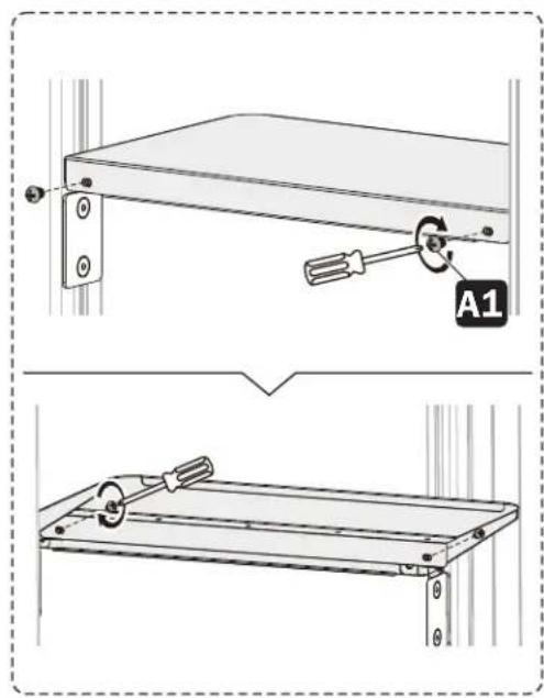
Adjustment
10
Note: To adjust the DVD shelf to the desired height, loosen the screws on both support blocks, then tighten all screws to secure.
Maintenance
- Check that the bracket is secure and safe to use at regular intervals (at least every three months).
- For any additional questions, visit tripplite.com/support.


1111 W. 35th Street, Chicago, IL 60609 USA • tripplite.com/support
21-06-299 932F2F_RerA
English 1 • Français 23 • Русский 34 • Deutsch 45
![TV 100 kg MÁXIMO DVD [220 lb] MÁXIMO 5 kg [11 lb] CÁMARA [x2] kg [11 lb] MÁXIMO](/content/2026/04/585297/images/5f39a22d24c32b29e2339ae0acb46f0409a492b3e88e8af145add737de6869b7.jpg)


1111 W. 35th Street, Chicago, IL 60609, EE. UU. • tripplite.com/support
Ensamble
5


Ensamble
6
Ensamble
7


Notas:

Ajuste

Mantenimiento


1111 W. 35th Street, Chicago, IL 60609, EE. UU. • tripplite.com/support
21-06-299 932F2F_RerA
English 1 • Español 12 • Русский 34 • Deutsch 45

MISE EN GARDE : NE PAS EXCÉDER LA CAPACITÉ PONDÉRALE MAXIMUM INDIQUÉE. CELA RISQUERAIT DE CAUSER DES BLESSURES GRAVES OU DES DOMMAGES MATÉRIELS!

200 × 200/300 × 300
400×200/400×400
600×400/800×400
800 x 600/1 000 x 600


Téléviseur DVD
100 kg/20 lb
MAX.

5 kg/11 lb (x2)5 kg/11 lb MAX.


D'excellence
Industrielle
1111 W. 35th Street, Chicago, IL 60609 USA • tripplite.com/support
Assemblage
5


Assemblage
6
Assemblage
7


Remarques :

Réglage

Entretien
1111 W. 35th Street, Chicago, IL 60609 USA • tripplite.com/support
21-06-299 932F2F_RerA
English 1 • Español 12 • Français 23 • Deutsch 45

∴ m = 3/11
кг
1111 W. 35th Street, Chicago, IL 60609 USA - tripplite.com/support

Порядок сборки
5


Порядок сборки
6
Порядок сборки
7


Примечания:


1111 W. 35th Street, Chicago, IL 60609 USA - tripplite.com/support
21 06 259 932F2F_Rest
Bedienungsanleitung
English 1 • Español 12 • Français 23 • Русский 34

Manufacturing Excellence.
1111 W. 35th Street, Chicago, IL 60609 USA • tripplite.com/support
M
Adapterwinkel links (x1)

C1
19 mm Schlüssel (x1)
Paket M

M-A
M5x14 (x4)

M-B
M6x14 (x4)
M-C
M6x30 (x4)
M-D
M8x30 (x4)
M-E
M8x50 (x4)

M-F
D5-D8 (x4)

M-G
∅15x∅8x5 (x8)

M-H
∅15x∅8x15 (x8)
Montage
1

2

Montage
5


Montage
6
Montage
7


Hinweise:

Einstellung

Wartung


1111 W. 35th Street, Chicago, IL 60609 USA • tripplite.com/support
21-06-299 932F2F_RerA
- HEAVY-DUTY ROLLING TV/MONITOR CART WITH CRANK HANDLE
- WARRANTY REGISTRATION
- SAFETY INSTRUCTIONS
- WARNING
- WARRANTY AND PRODUCT REGISTRATION
- 5-YEAR LIMITED WARRANTY
- PRODUCT REGISTRATION
- COMPONENT CHECKLIST
- PACKAGE P
- PACKAGE M
- ASSEMBLY
- 6
- NOTES
- ADJUSTMENT
- MAINTENANCE
- ENSAMBLE
- NOTAS
- AJUSTE
- MANTENIMIENTO
- ASSEMBLAGE
- REMARQUES
- RÉGLAGE
- ENTRETIEN
- ПОРЯДОК СБОРКИ
- ПРИМЕЧАНИЯ
- BEDIENUNGSANLEITUNG
- PAKET M
- MONTAGE
- HINWEISE
- EINSTELLUNG
- WARTUNG
Brand : Tripp Lite
Model : DMCS60100XXCK
Category : TV Mount