
pAD - Thermostat Carel - Free user manual and instructions
Find the device manual for free pAD Carel in PDF.
| Product Type | Room thermostat / Control terminal |
| Brand | Carel |
| Model | pAD |
| Supply voltage | 24 Vac ±15% (50/60 Hz) or 31 Vdc ±29% |
| Power consumption | Max 1.5 VA (AC) / 70 mA (DC) |
| Integrated sensors | NTC temperature (all models), humidity (models ADPG, ADPH) |
| Communication interface | RS485 (pLAN protocol, Carel/Modbus) |
| Operating modes | Heating, cooling, humidification, dehumidification, automatic |
| Temperature setpoint adjustment | Yes, via UP/DOWN keys |
| Humidity setpoint adjustment | Yes (models with humidity sensor) |
| Time scheduling | 2 time bands for weekdays and weekends |
| Night mode (Sleep) | Yes, timed up to 9 hours |
| Display | LCD with icons (temperature, humidity, mode, clock, alarms) |
| Real-time clock (RTC) | Yes (on models with RTC backup) |
| Fan management | 3 manual or automatic speeds |
| Alarms | Display of pCO controller alarms (offline, defective probe, etc.) |
| Protection | IP30, class III, pollution degree II |
| Operating temperature | 0 to 50 °C |
| Operating humidity | 10 to 85% RH (non-condensing) |
| Maintenance | Clean with soft cloth, do not use water or chemicals |
| Safety | Installation by qualified personnel, follow mounting instructions, protection against electrostatic discharge |
| Weight | Not specified (lightweight estimate, < 200 g) |
| Dimensions | See diagram in manual (wall mounting) |
Frequently Asked Questions - pAD Carel
User questions about pAD Carel
0 question about this device. Answer the ones you know or ask your own.
Ask a new question about this device
Download the instructions for your Thermostat in PDF format for free! Find your manual pAD - Carel and take your electronic device back in hand. On this page are published all the documents necessary for the use of your device. pAD by Carel.
USER MANUAL pAD Carel
CAREL bases the development of its products on decades of experience in HVAC, on the continuous investments in technological innovations to products, procedures and strict quality processes with in-circuit and functional testing on 100% of its products, and on the most innovative production technology available on the market. CAREL and its subsidiaries nonetheless cannot guarantee that all the aspects of the product and the software included with the product respond to the requirements of the final application, despite the product being developed according to start-of-the-art techniques.
The customer (manufacturer, developer or installer of the final equipment) accepts all liability and risk relating to the configuration of the product in order to reach the expected results in relation to the specific final installation and/or equipment.
CAREL may, based on specific agreements, acts as a consultant for the positive commissioning of the final unit/application, however in no case does it accept liability for the correct operation of the final equipment/system.
The CAREL product is a state-of-the-art product, whose operation is specified in the technical documentation supplied with the product or can be downloaded, even prior to purchase, from the website www.carel.com.
Each CAREL product, in relation to its advanced level of technology, requires setup / configuration / programming / commissioning to be able to operate in the best possible way for the specific application. The failure to complete such operations, which are required/indicated in the user manual, may cause the final product to malfunction; CAREL accepts no liability in such cases.
Only qualified personnel may install or carry out technical service on the product.
The customer must only use the product in the manner described in the documentation relating to the product.
In addition to observing any further warnings described in this manual, the following warnings must be heeded for all CAREL products:
- Prevent the electronic circuits from getting wet. Rain, humidity and all types of liquids or condensate contain corrosive minerals that may damage the electronic circuits. In any case, the product should be used or stored in environments that comply with the temperature and humidity limits specified in the manual.
- Do not install the device in particularly hot environments. Too high temperatures may reduce the life of electronic devices, damage them and deform or melt the plastic parts. In any case, the product should be used or stored in environments that comply with the temperature and humidity limits specified in the manual.
- Do not attempt to open the device in any way other than described in the manual.
- Do not drop, hit or shake the device, as the internal circuits and mechanisms may be irreparably damaged.
- Do not use corrosive chemicals, solvents or aggressive detergents to clean the device.
- Do not use the product for applications other than those specified in the technical manual.
All of the above suggestions likewise apply to the controllers, serial boards, programming keys or any other accessory in the CAREL product portfolio.
CAREL adopts a policy of continual development. Consequently, CAREL reserves the right to make changes and improvements to any product described in this document without prior warning.
The technical specifications shown in the manual may be changed without prior warning.
The liability of CAREL in relation to its products is specified in the CAREL general contract conditions, available on the website www.carel.com and/or by specific agreements with customers; specifically, to the extent where allowed by applicable legislation, in no case will CAREL, its employees or subsidiaries be liable for any lost earnings or sales, losses of data and information, costs of replacement goods or services, damage to things or people, downtime or any direct, indirect, incidental, actual, punitive, exemplary, special or consequential damage of any kind whatsoever, whether contractual, extra-contractual or due to negligence, or any other liabilities deriving from the installation, use or impossibility to use the product, even if CAREL or its subsidiaries are warned of the possibility of such damage.
DISPOSAL

INFORMATION FOR USERS ON THE CORRECT HANDLING OF WASTE ELECTRICAL AND ELECTRONIC EQUIPMENT (WEEE)
In reference to European Union directive 2002/96/EC issued on 27 January 2003 and the related national legislation, please note that:
- WEEE cannot be disposed of as municipal waste and such waste must be collected and disposed of separately;
the public or private waste collection systems defined by local legislation must be used. In addition, the equipment can be returned to the distributor at the end of its working life when buying new equipment; -
the equipment may contain hazardous substances; the improper use or incorrect disposal of such may have negative effects on human health and on the environment;
the symbol (crossed-out wheeled bin) shown on the product or on the packaging and on the instruction sheet indicates that the equipment has been introduced onto the market after 13 August 2005 and that it must be disposed of separately; -
in the event of illegal disposal of electrical and electronic waste, the penalties are specified by local waste disposal legislation.
Contents
- INTRODUCTION 22
1.1 Presentation of the pAD 22
1.2 Main functions of the pAD 22
1.3 pAD models 22
- USER INTERFACE 22
2.1 Display 22
2.2 Standard user interface 22
2.3 Main alternative functions of the buttons 22
- INSTALLATION 23
3.1 Assembly and installation instructions 23
3.2 Power supply connections 23
3.3 Serial interface 23
3.4 Installation warnings 23
-
CONFIGURATION AND STARTING 24
-
FUNCTIONS 25
5.1 Device ON/STANDBY 25
5.2 Cooling 25
5.3 Heating 25
5.4 Setting the temperature set point 25
5.5 Humidify 26
5.6 Dehumidify 26
5.7 Setting the humidity set point 26
5.8 Sleep mode 26
5.9 Setting the clock 26
5.10 Time bands.. 27
- LIST OF ALARMS 27
- TECHNICAL SPECIFICATIONS 28
1. INTRODUCTION
1.1 Presentation of the pAD
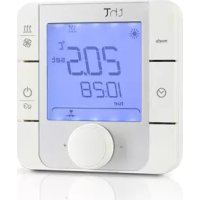
pAD is the wall-mounted LCD room terminal with icon-based display for use with pCO controllers. It is available in two models: with temperature sensor or temperature + humidity sensors.
Depending on the model, pAD can be connected to the pLAN port or Field Bus RS485 port. The clock, available on some models for managing time bands, and the attractive design, make the display suitable for residential or commercial applications.
1.2 Main functions of the pAD
Functions of the pAD include:
- configuration and display of the temperature and humidity set point
- reading of temperature and/or humidity sensors
time band management - manual and automatic heating / cooling mode changeover
manual and automatic fan speed setting (3 speed)
clock setting / display
display of alarms from the pCO controller connected to the pAD
management of "sleep mode"
display of icons (COOLING,HEATING...)
synchronisation of the clock on the pCO controller with the clock on the pAD
1.3 pAD models
| Code | Description |
| ADPB003000 | pAD NTC, buzzer |
| ADPB003010 | pAD NTC, backup RTC, buzzer |
| ADPC003000 | pAD NTC, backlight, buzzer |
| ADPC003010 | pAD NTC, backup RTC, backlight, buzzer |
| ADPG003000 | pAD NTC, humidity sensor, buzzer |
| ADPG003010 | pAD NTC, humidity sensor, backup RTC, buzzer |
| ADPH003000 | pAD NTC, humidity sensor, backlight, buzzer |
| ADPH003010 | pAD NTC, humidity sensor, backup RTC, backlight, buzzer |
2. USER INTERFACE
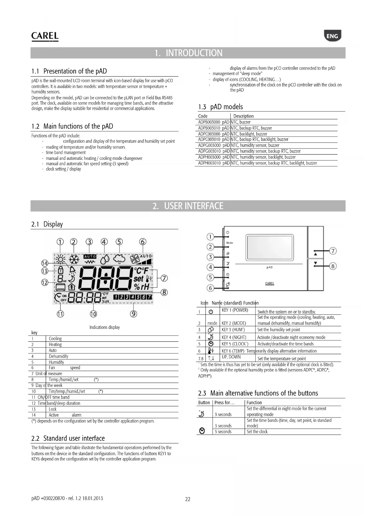
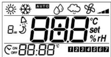
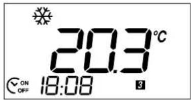
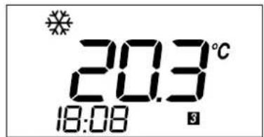
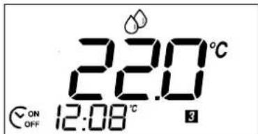
2.1 Display
Indications display
| key | ||
| 1 | Cooling | |
| 2 | Heating | |
| 3 | Auto | |
| 4 | Dehumidify | |
| 5 | Humidity | |
| 6 | Fan speed | |
| 7 | Unit of measure | |
| 8 | Temp./humid./set (*) | |
| 9 | Day of the week | |
| 10 | Tim/tem,./humid,/set (*) | |
| 11 | ON/OFF time band | |
| 12 | Time band/sleep duration | |
| 13 | Lock | |
| 14 | Active alarm | |
(*) depends on the configuration set by the controller application program.
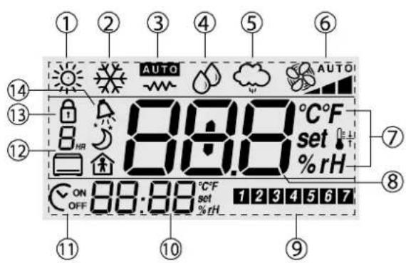
2.2 Standard user interface
The following figure and table illustrate the fundamental operations performed by the buttons on the device in the standard configuration. The functions of buttons KEY1 to KEY6 depend on the configuration set by the controller application program.
Icdn Name (standard) Functi
| 1 | KEY 1 (POWER) | Switch the system on or to standby. | |
| 2 | mode | KEY 2 (MODE) | Set the operating mode (cooling, heating, auto, manual dehumidity, manual humidify) |
| 3 | KEY 3 (HUM') | Set the humidity set point | |
| 4 | KEY 4 (NIGHT) | Activate/deactivate night economy mode | |
| 5 | KEY 5 (CLOCK') | Activate/deactivate the time bands | |
| 6 | KEY 6 (TEMP) Temporarily display alternative information | ||
| 7.8 | ↑,↓ | UP, DOWN | Set the temperature set point |
Sets the time is thus has yet to be set (only available if the optional clock is fitted).
Only available if the optional humidity probe is fitted (versions ADPC, ADPG, ADPH*).
2.3 Main alternative functions of the buttons
| Button | Press for... | Function |
| 3 seconds | Set the differential in night mode for the current operating mode | |
| 3 seconds | Set the time bands (time, day, set point, in standard mode) | |
| 5 seconds | Set the clock |
3. INSTALLATION
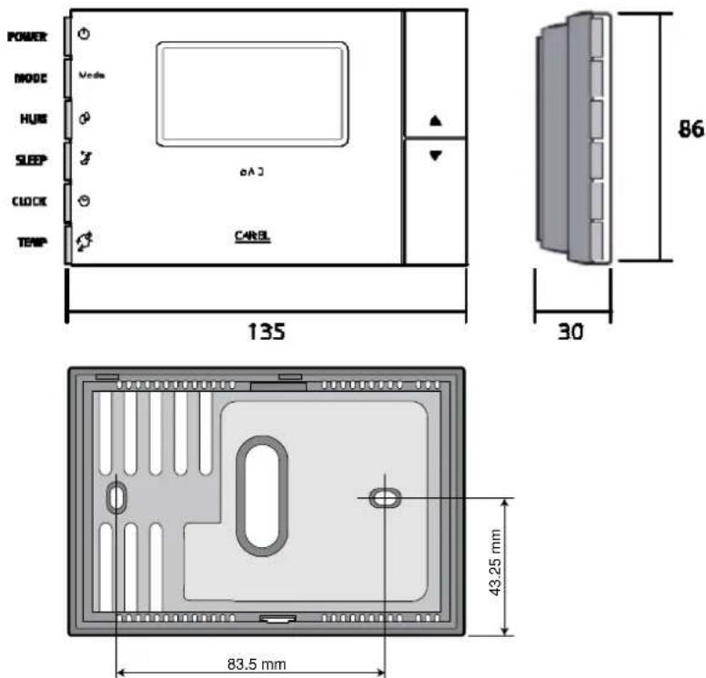
3.1 Assembly and installation instructions.

Disconnect the power supply before working on the device during assembly, maintenance and replacement.
The spacing of the mounting holes is designed so that the device can be fitted to a flush-mounted sockets, compliant with standards CEI C.451 - IEC 670. If a socket is not available, use the mounting holes on the shell as a template for drilling the wall, and then use the screws and wall plugs supplied.
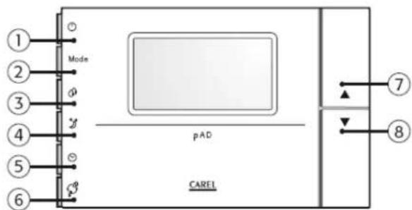
The connection cables must run through the hole in the centre of the rear shell of the device, and must be fastened to the terminals on the shell.
Inside view of the rear shell
To access the connection terminals, release the rear shell by levering the locking tab. The device must be flipped open, with the "hinge" at the top of the instrument and lifting the bottom. When closing, make sure that the pins on the board are inserted into the corresponding terminals, and that the cables do not get in the way.
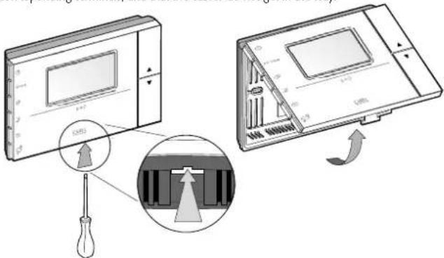
Bottom view

Adopt precautions against electrostatic discharges when handling the board. Do not touch or nearly touch the electronic components on the boards to avoid electrostatic discharges from the person handling the board to the components.
3.2 Power supply connections

Observe the following warnings:
The power supply terminals on the device are marked G and G0. The connection is made using 2-pin screw terminals fastened to the rear shell of the instrument. Use cables with a cross-section from 0.5 to 1.5mm^2
A dedicated 250 mAT fuse must be installed externally, between the power supply and terminal G;
use a class 2 safety transformer with a minimum rating of 4 VA.
If the transformer or power supply used for the device is the same used for the controllers connected in the serial line, then terminal GO on the pAD must be connected to the GO line of the controllers.
Important: if a terminal of the power supply needs to be earthed, use terminal GO (and NOT terminal G), both on the pAD the other powered devices.
- When pAD has a DC power supply, the controllers connected via the serial interface must also have a DC power supply. If the controllers connected do not allow DC power, (see the manual for the controllers) then the pAD cannot have a DC power supply.
The power supply or the power transformer used must guarantee double or reinforced insulation between the high voltage mains and the terminal.
3.3 Serial interface
pAD uses an RS485 serial interface for communication with the controllers, via 3-pin plug-in terminals. Use a shielded twisted pair cable, AWG20-22, with the total length of the network not exceeding 500m . The capacitance between the wires must not be greater than 90~pF / m

To reach the maximum length, use a bus layout with branches that do not 5 m.
Further limits to the length may be required in environments with considerable electrical disturbance. See the controller manual to determine the connections.
Protocols supported:
pLAN protocol via RS485. The pLAN network is made up of a series of controllers and terminals that interact with each other, exchanging variables and information. The physical limit is 32 units, with a maximum of 30 pAD devices.
- Carel / Modbus via RS485 (in the models where available)
3.4 Installation warnings
Avoid installing the boards in environments with the following characteristics:
relative humidity greater than the value specified;
- strong vibrations or knocks;
exposure to water sprays;
-
exposure to aggressive and polluting atmospheres(e.g.: sulphur and ammonia fumes, saline mist, smoke) so as to avoid corrosion and/or oxidation;
-
strong magnetic and/or radio frequency interference (for example, near transmitting antennae);
-
exposure to direct sunlight or the elements in general;
- large and rapid fluctuations in the room temperature;
- environments where explosives or mixes of flammable gases are present;
- exposure to dust (formation of corrosive patina with possible oxidation and reduction of insulation).

Further information
- A power supply other than the one specified may seriously damage the system.
- Important: if the device is used in a way that is not specified by the manufacturer, the protection of the device may be compromised.
- Use cable ends suitable for the corresponding terminals. Loosen each screw and insert the cable ends, then tighten the screws. When the operation is completed, slightly tug the cables to check they are sufficiently tight.
- To clean the display use a soft cloth. Do not use water.
- Operation at particularly low temperatures may cause a visible decline in the response speed of the display. This should be considered normal and does not indicate a malfunction.
- The terminal must be fastened to the wall in such a way as to allow the recirculation of air through the slits on the rear shell. Avoid places where the room temperature measurement may be altered, for example outside walls, near doors leading to the outside or in direct sunlight.
- Separate the cables running to the device from cables that supply inductive loads and power cables, so as to avoid possible electromagnetic disturbance. Never use the same conduits for the power cables (including other electrical cables) and serial communication cables. Do not install the communication cables in the immediate vicinity of power devices (contactors, circuit breakers or similar).
4. CONFIGURATION AND STARTING
When started, the pAD, after having completed the initialisation procedure, shows
888 in the temperature display for a few seconds, indicating that it is researching for the pCO controller connected to the data line.
To access the parameters, proceed as follows:
- press the UP button;
- within three seconds press the DOWN button;
- when "PAr" is displayed in the main area, release the DOWN button while holding the UP button and press KEY6 within three seconds.
Procedure for setting the parameters
In this mode, all the symbols are off, except for the following fields:
888 indicates the value of the parameter currently being set;
88:88 indicates the name of the parameter currently being set
To set the parameters, proceed as follows:
- The 88:88 field flashes. Use the UP/DOWN buttons to select the parameter to be set, then press KEY6 or (PRG).
- The 888 field flashes. Use the UP/DOWN buttons to set the desired value, then press KEY6.
- Repeat the actions from point 1 until completing all the desired operations
- To exit the parameter setting procedure, saving the changes made, simply hold KEY6 for 3 seconds.
To exit the parameter setting procedure without saving the changes, simply wait 60 seconds from when the last button was pressed, or press KEY4; 45 seconds after the last button was pressed the name or the value of the parameter flashes.
If the communication parameters are changed (Ad01 and/or Br01), communication will be re-initialised by the pAD.
The table below describes the meaning of the operating parameters.
| Name | Description | Min | Max | UOM | Def. | |
| Ad01 | pAD pLAN network address 1 | 32 - 2 | ||||
| Ad02 * | Supervisor address | 1 | 255 | - | 1 | |
| Br01 | pLAN baud rate | 0 (62.5 Kbps) | 1 (115.2 kbps) | - | 0 | |
| Br02 * | Supervisor baud rate | 0 | 4 | - | 4 | |
| En01 | Enable buzzer | 0 | 1 | - | 1 | |
| Pc01 | Room probe calibration | -9.9 | +9.9 | °C/°F | 0.0 | |
| rEL | Firmware release | - | - | - | - | |
| Prot * | Select protocol | 1 | 3 | 1 | 1 | |
- indicates the parameters that are only available in the versions that support the Corel/Modbus protocols.
In the models configured for the Carel/Modbus protocols, Supervisor baud rate values correspond to the following parameter settings:
| Br02 | 0 | 1 | 2 | 3 | 4 |
| Baud rate | 1200 | 2400 | 4800 | 9600 | 19200 |
The protocol used is set by parameter Prot, which can have the following values:
| Prot | 1 | 2 | 3 |
| protocol | pLAN | Carel | Modbus |
5. FUNCTIONS
The settings/descriptions of the following functions may change depending on the application program running on the controller that the terminal is connected to.
5.1 Device ON/STANDBY
The POWER button is used to start (ON) and stop (PERMANENT or TEMPORARY) the device. The setting is maintained even when there is no power supply.

pAD does not have an OFF switch; whenever power is connected, it starts operating. The POWER button simply starts/stops the temperature and/or humidity control functions in the area where the terminal is installed.
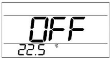
Procedures required based on the message shown on the display pAD in permanent STANDBY
(the display shows OFF)
To enable operation in the previous mode, press the POWER button; OFF is no longer displayed;
If time band operation was NOT previously activated :
time band operation remains OFF;
the ONOFF symbol remains off;
- operation is activated in the mode previously set using the mode button;
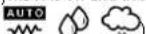
- one or more of the following symbols will be on:

If time band operation was previously activated (see the paragraph on "Time bands"):
time band operation starts again;
- the ON OFF symbol comes on
- operation depends on the active time band.
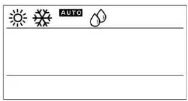
PAD ON - TIME BANDS NOT ACTIVE
(the _OFF^ON symbol is off and the display shows one or more of the following symbols:

To stop the system (PERMANENT STANDBY), press the POWER button for 3 seconds until the main field on the display shows OFF; all the symbols will be switched off.
pAD ON AND TIME BANDS ACTIVE
(the symbol is on)
to temporarily activate/deactivate the operation of the system (ON/TEMPORARY STANDBY, that is, "override" the time bands), briefly press POWER; one or more of the symbols -
- will come on (alternatively, all the
symbols will go off); the ON symbol remains on; when the next switching time is reached (see the paragraph on "Time bands"), pAD will apply the corresponding settings to the system;
to shut down the system, press POWER for 3 seconds: the main field
displays OFF (PERMANENT STANDBY); the ON symbol and all the other symbols will be off.

The possibility to activate cooling in the zone managed and functions of the buttons depend on the configuration set by the controller application program.
5.2 Cooling
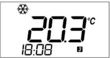
To activate cooling operation in the zone controlled by the pAD terminal.
Make sure that the system is operating (see the paragraph "system ON/STANDBY").
Press MODE repeatedly until the display shows the COOLING symbol

The possibility to activate cooling in the zone managed and functions of the buttons depend on the configuration set by the controller application program.
5.3 Heating
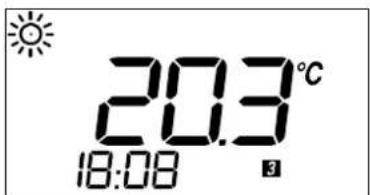
To activate heating operation in the zone controlled by the pAD terminal.
Make sure that the system is operating (see the paragraph "system ON/STANDBY").
Press MODE repeatedly until the display shows the HEATING symbol

The possibility to activate heating in the zone managed and functions of the buttons depend on the configuration set by the controller application program.
5.4 Setting the temperature set point
To set the temperature set point in the zone controlled by the pAD terminal.
- Press the or buttons; the main area of the pAD will display the current set point.
To the right of the value, the set symbol comes on (flashing). - Pressing , again changes the set point.
The procedure for setting the temperature set point ends automatically 3 seconds after the last button was pressed.

If the setting of the temperature set point is not accessible to the user, the lock symbol will be displayed.
If time bands have been configured in pAD mode (see the paragraph on "Time bands") and these are active, the new value will only be valid until the end of the current time band. If, on the other hand, the time bands are managed directly by the pCO controller, these will be controlled exclusively by the pCO, based on the selected set point.
5.5 Humidify
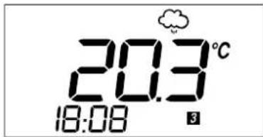
To activate humidification in the zone controlled by the pAD terminal (if the model of pAD purchased features the humidity sensor)
Make sure that the system is operating (see the paragraph "system ON/STANDBY").
Press MODE repeatedly until the display shows the HUMIDIFY symbol

The possibility to activate humidification in the zone managed and functions of the buttons depend on the configuration set by the controller application program.
5.6 Dehumidify

To activate dehumidification in the zone controlled by the pAD terminal (if the model of pAD purchased features the humidity sensor).
Make sure that the system is operating (see the paragraph "system ON/STANDBY").
Press MODE repeatedly until the display shows the DEHUMIDIFY symbol

The possibility to activate dehumidification in the zone managed and functions of the buttons depend on the configuration set by the controller application program.
5.7 Setting the humidity set point
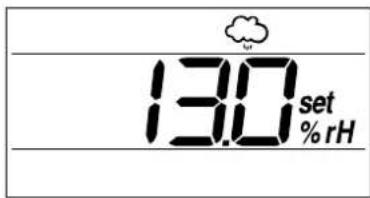
To set the humidity set point in the zone controlled by the pAD terminal.
Press the button associated with the humidity set point setting (default KEY 3)
- Press the buttons or buttons; the main area of the pAD will display the current set point.
To the right of the value the % rH and symbols come on (the latter flashing).
- Pressing , again changes the set point.
The procedure for setting the humidity set point ends automatically 3 seconds after the last button was pressed.

If the setting of the humidity set point is not accessible to the user, the lock
symbol will be displayed.
5.8 Sleep mode
This mode is used to increase the room temperature set point in cooling (an decrease it in heating) at certain times. It is useful for improving comfort and ensuring energy saving.
Procedure:
Press the button (KEY4 by default). If the mode is already active, it is deactivated. If not already active, it will be activated, and the symbol will be displayed. The field displays "1", flashing, indicating that "Sleep" mode will be active for one hour. Pressing the button again within 3 seconds increases the duration of "Sleep" mode, up to a maximum of 9 hours.

The number shown in the field is rounded up to the next hour, that is,
if the remaining time is "1 hour and 1 minute", "2_Hs" is displayed.
The Sleep function also features a differential, which represents the temperature difference from the set point in the area managed by the pAD.
To set the differential:
- Hold the button (KEY4 by default) for 3 seconds.
the 888 field becomes the Sleep differential setting (the value displayed corresponds to the current operating mode set during configuration, or the default value, and the 88:88 field display "diff").
Set the desired value using the UP/DOWN buttons. The range of values available is from 0.0 (disabled) to 10.0^ / ^oF (Default at startup = 2.0 ).
Press the NIGHT button again to confirm or wait 3 seconds for automatic confirmation.
Pressing the button deactivates the Sleep function, displaying the LOCK symbol in the following cases:
when the function is disabled by the pCO controller;
- whenever the instrument is switched on;
- when the preset time has elapsed, the mode is disabled automatically. In OFF status, the setting is disabled, as signalled on the pAD by the flashing message. The pAD has a built-in timer for managing the duration of SLEEP mode, when active.
5.9 Setting the clock
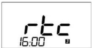
To set the clock on the pAD (if the model of pAD purchased features the RTC).
Press the button for 5 seconds (KEY5 by default), the display shows "rtc" and the current time (flashing).
Press the or button to set the hours (0 to 23),
Press the button to save the hours and set the minutes
Press the or button to set the minutes (0 to 59),
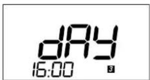
- Press the button to save the minutes and configure the current day.
The display shows "day". The current day field flashes
Press the or button to set the day (0 to 7),
Press the button to end the procedure.

- After extended power failures the time will need to be reset.
- As the pAD is the room terminal for the pCO controller, the choice of whether to use the clock on board the terminal or on the controller depends on the configuration set by the pCO controller application program.
5.10 Time bands
When setting operation controlled by time bands, the status (STANDBY/ON) and the corresponding set point can be programmed for certain times. The following are available:
2 common time bands for the first five days of the week (Monday-Friday)
2 common time bands for the last two days (Saturday-Sunday).
Setting the times and the actions
The time bands menu displays the following settings, in sequence:
time band 1 (HH) for days 1 to 5;
time band 1 (MM) for days 1 to 5;
time band 1 (ACTION) for days 1 to 5;
time band 2 (HH) for days 1 to 5;
time band 2 (MM) for days 1 to 5;
time band 2 (ACTION) for days 1 to 5;
time band 1 (HH) for days 6 to 7;
time band 1 (MM) for days 6 to 7;
time band 1 (ACTION) for days 6 to 7;
time band 2 (HH) for days 6 to 7;
time band 2 (MM) for days 6 to 7;
time band 2 (ACTION) for days 6 to 7.
Procedure:
- press for 3 seconds: the symbol for days 1 to 5 comes on and
the 1234567 field shows the number of the time band. Symbol 17 flashes, field 18 displays time band 1, the hour digits flash;

holding
The
button erroneously for more than 5 seconds
enters clock setting mode; to exit, simply press 3 times, then start again.
-
set the desired value (0 to 23) using or ;
-
press
to set the minutes;
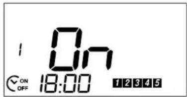
- press to set the action for the time band: the main display shows one of the following values:
OFF: at the set time pAD will switch to STANDBY;
ON: at the set time pAD will switch ON;
A temperature set point: at the set time this set point will be used as the set point on the pAD;
use or to select: OFF, ON or a set point;
- press to continue the settings for time band 2; the display shows the

symbol for days 6 and 7 in the
7234567
times later than the value set for time band 1 are allowed;
- for each setting, the following options are available:
continue setting the other time bands;
or press

to end, saving the settings:
or wait 1 minute without pressing any button: the procedure
will end automatically, saving any settings made
6. LIST OF ALARMS
The settings/descriptions of the following functions may change depending on the application program running on the controller that the terminal is connected to.
If an alarm situation occurs during operation, the terminal will show the symbol flashing and, alternating with the normal display, the alarm code every 2 seconds. The meaning of the codes is shown below:
| Alarm | Meaning |
| Alr * Active | alarm on the controller. Shown while the alarm is active |
| oLn Offline | no communication between the device and the pLAN network |
| AtE | Temperature alarm: internal temperature sensor fault or sensor missing |
| Ahu | Humidity alarm: internal humidity sensor fault or sensor missing |
- This is the default string. The pAD shows the string sent by the controller, if the latter requires, using the corresponding variable (this depends on the application running on the controller).
7. TECHNICAL SPECIFICATIONS
| Power supply (to EN60730-1) | 24 Vac ± 15 %, 50/60 Hz 70 mA 1.5 VA or 31 Vdc ± 29 % 70 mA |
| Classification as per UL873 | Power supply input: 24 Vac, 50/60 Hz, Class 2 25.5 - 36.25 Vdc, Class 2 Power consumption, max 1 watt Outputs: RS485 serial link, Class 2 |
| Operating conditions: 0T50 °C; 10 to 85% rH non-condensing | |
| Storage conditions: -20T70 °C; 0 to 85% rH non-condensing | |
| Dimensions: See the figure below | |
| Environmental pollution: Normal | |
| Degree of pollution: 2 | |
| Category: of resistance to heat and fire A | |
| Software class and structure: A | |
| Index of protection: IP30 | |
| Ball pressure test temperature on the plastic used for the case | 100 °C |
| Classification according to protection against electric shock (EN60703-1) 3, to be integrated into class 1 or 2 appliances | |
| Period of electrical stress across the insulating parts: long | |
| Protection against short-circuits | Must be guaranteed by the manufacturer of the appliance that pAD is integrated into or by the installer |
| Immunity against voltage surges | Category 1 |
| Cross-section of the wires | From 0.5 to 1.5 mm² |
| Precision of temperature measurement | +/-2 °C |
| Precision of humidity measurement (in the models fitted with humidity probe) | +/-10 % rH |
Dimensions:
CAREL reserves the right to modify or change its products without prior warning.
FRE
ATTENTION

pAD ON - TRANCHES HORAIRES NON ACTIVÉS
pAD EN FONCTIONNEMENT ET AVEC TRANCHES HORAIRES ACTIVÉES
5.6 Deshumidification
- DISPOSAL
- INFORMATION FOR USERS ON THE CORRECT HANDLING OF WASTE ELECTRICAL AND ELECTRONIC EQUIPMENT (WEEE)
- Contents
- INTRODUCTION
- Presentation of the pAD
- Main functions of the pAD
- pAD models
- USER INTERFACE
- Display
- Standard user interface
- Main alternative functions of the buttons
- INSTALLATION
- Assembly and installation instructions.
- Power supply connections
- Serial interface
- Protocols supported:
- Installation warnings
- Further information
- CONFIGURATION AND STARTING
- FUNCTIONS
- Device ON/STANDBY
- PAD ON - TIME BANDS NOT ACTIVE
- pAD ON AND TIME BANDS ACTIVE
- Cooling
- Heating
- Setting the temperature set point
- Humidify
- Dehumidify
- Setting the humidity set point
- Sleep mode
- Procedure:
- Setting the clock
- Time bands
- LIST OF ALARMS
- TECHNICAL SPECIFICATIONS
- ATTENTION
- Deshumidification
Brand : Carel
Model : pAD
Category : Thermostat