
Fathom IWSv2SYS213 - Subwoofer JL Audio - Free user manual and instructions
Find the device manual for free Fathom IWSv2SYS213 JL Audio in PDF.
| Product Type | Amplified in-wall subwoofer |
| Brand | JL Audio |
| Model | Fathom IWSv2SYS213 |
| Speakers | 2 x 34 cm (13.5 in) nominal diameter |
| Amplifier Power | 2,000 watts RMS short term |
| Frequency Response (anechoic) | 26 – 101 Hz (±1.5 dB); –3 dB at 25 Hz / 112 Hz; –10 dB at 22 Hz / 150 Hz |
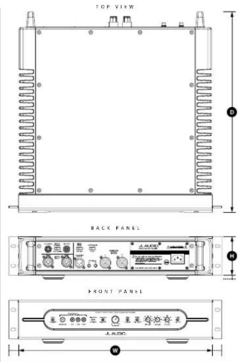
| Amplifier Dimensions (H x W x D) | 89 mm x 442 mm x 455 mm |
| Amplifier Weight | 19.5 kg |
| Grille Dimensions (H x W) | 448 mm x 435 mm |
| Required Wall Opening (W x H) | 406 mm x 419 mm |
| Power Supply | 120 V or 240 V depending on regional configuration (fast-acting fuse 12 A / 8 A) |
| Standby Power Consumption | Less than 10 watts |
| Inputs | Balanced (XLR/TRS) and unbalanced (RCA) stereo or mono |
| Speaker Outputs | Neutrik speakOn® NL2FX connectors (2-pole) |
| Main Functions | DARO (Digital Automatic Room Optimization), variable low-pass filter (30-130 Hz, slopes 12/24 dB/oct), phase adjustment (0-270°), polarity (0/180°), e.l.f. trim filter (-12 dB to +3 dB at 23 Hz), master/slave mode, 12 V trigger |
| Cleaning and Maintenance | Clean with a dry, soft cloth. Do not use abrasive products. Disconnect before cleaning. |
| Safety | Do not expose to water or moisture. Do not block ventilation. Disconnect during thunderstorms or when not in use for extended periods. |
| Spare Parts and Repairability | Main fuse replaceable by user. Any other repair must be carried out by a qualified technician. |
| Warranty | Limited warranty (see manual for details) |
Frequently Asked Questions - Fathom IWSv2SYS213 JL Audio
User questions about Fathom IWSv2SYS213 JL Audio
0 question about this device. Answer the ones you know or ask your own.
Ask a new question about this device
Download the instructions for your Subwoofer in PDF format for free! Find your manual Fathom IWSv2SYS213 - JL Audio and take your electronic device back in hand. On this page are published all the documents necessary for the use of your device. Fathom IWSv2SYS213 by JL Audio.
USER MANUAL Fathom IWSv2SYS213 JL Audio
IMPORTANT SAFETY INSTRUCTIONS
WARNING: TO REDUCE THE RISK OF FIRE OR ELECTRIC SHOCK, DO NOT EXPOSE THIS PRODUCT TO RAIN OR MOISTURE.
CAUTION
RISK OF ELECTRIC SHOCK DO NOT OPEN

CAUTION: TO REDUCE THE RISK OF ELECTRIC SHOCK, DO NOT REMOVE COVER. NO USER SERVICEABLE PARTS INSIDE. REFER SERVICING TO QUALIFIED PERSONNEL.
- Read the Instructions — All safety and operating instructions should be read before the subwoofer is operated.
- Retain the Instructions — The safety and operating instructions should be retained for future reference.
- Heed Warnings — All warnings on the subwoofer and in the operating instructions should be followed.
- Follow Instructions — All operating and use instructions should be followed.
- Water and Moisture — The subwoofer should NOT be used near water – for example, near a bathtub, washbowl, sink, laundry tub, in a wet basement, near a swimming pool, etc.
- Ventilation — The subwoofer amplifier should be situated so that its location or position does not interfere with its proper ventilation. For example, the subwoofer amplifier should not be situated on a bed, sofa, rug, or similar surface that may block airflow over the heatsink fins. If placing the subwoofer amplifier in a “built-in” installation, ensure that airflow to the heat sinks are not impeded. Do not cover the amplifier heatsink with tablecloths, curtains, etc.
- Heat and Flames — The subwoofer and amplifier should be situated away from heat sources such as radiators, heat registers, stoves, fireplaces, or other devices which produce heat. Do not place candles on top of or near the subwoofer or amplifier.
- Power sources — The subwoofer should only be connected to a power supply of the type described in the operating instructions or as marked on the product.
- Power Cord Protection — Power-supply cords should be routed so that they are not likely to be walked on or pinched by items placed upon or against them, paying particular attention to cords at plugs, convenience receptacles, and the point where they exit the subwoofer.
- Cleaning — The subwoofer and amplifier should be cleaned only as recommended in the operating instructions.
- Nonuse Periods — The power cord of the subwoofer amp should be unplugged from the outlet when the subwoofer is left unused for long periods of time.
- Lightning and Power Surges — We recommend that you disconnect the subwoofer amp from the electrical outlet during electrical storms and/or recurring power interruptions to prevent damage due to power surges.
The lightning flash with arrowhead symbol, within an equilateral triangle, is intended to alert the user to the presence of uninsulated “dangerous voltage” within the product’s enclosure that may be of sufficient magnitude to constitute a risk of electric shock to persons.

The exclamation point within an equilateral triangle is intended to alert the user to the presence of important operating and maintenance instructions in the literature accompanying the product.
-
Object or Liquid Entry — Care should be taken so that objects do not fall into and liquids are not spilled onto the subwoofer enclosure. Do not expose the subwoofer to dripping or splashing from liquids. Do not place objects filled with liquids on top of, or near the subwoofer or amplifier. For example: flower vases, beverages, liquid-fueled lamps, etc.
-
Damage Requiring Service — The subwoofer should be serviced by qualified service personnel when:
a. the power-supply cord or plug has been damaged
b. objects have fallen or liquid has been spilled into the subwoofer
c. the subwoofer has been exposed to rain
d. the subwoofer does not appear to operate normally or exhibits a marked change in performance
e. the subwoofer has been dropped or the cabinet has been damaged
f. the subwoofer driver's cone and/or suspension has been physically damaged
- Servicing — The user should not attempt to service the subwoofer beyond what is described in the operating instructions. All other servicing should be referred to qualified service personnel.
- Overloading — Do not overload wall outlets, extension cords, or outlet strips as this can result in a risk of fire or electric shock.
- Grounding — This subwoofer is supplied with a three-prong, grounded power cord. Precautions should be taken so that the grounding means of the subwoofer are not defeated. Defeating the grounding prong on the subwoofer power cord could increase the risk of electric shock and could result in permanent damage to the subwoofer's electronics.
WARNING

THIS SUBWOOFER IS CAPABLE OF PRODUCING VERY HIGH SOUND PRESSURE LEVELS. PLEASE EXERCISE RESTRAINT IN ITS OPERATION TO PROTECT YOUR HEARING FROM PERMANENT DAMAGE.
FCC COMPLIANCE STATEMENT
NOTE: This equipment has been tested and found to comply with the limits of Part 15 of the FCC Rules. These limits are designed to provide reasonable protection against harmful interference in a residential installation. This equipment generates, uses and can radiate radio frequency energy and, if not installed in accordance with the instructions, may cause harmful interference to radio communications. However, there is no guarantee that interference will not occur in a particular installation. If this equipment does cause harmful interference to radio or television reception, which can be determined by turning the equipment off and on, the user is encouraged to try to correct the interference by one or more of the following measures:
- Reorient or relocate the receiving antenna.
- Increase the separation between the equipment and receiver.
- Connect the equipment into an outlet on a circuit different from that to which the receiver is connected.
- Consult the dealer or an experienced radio/TV technician for help.
TABLE OF CONTENTS
Important Safety Instructions: 2-3
Introduction: 4
Product Overview / Package Contents: 5
Placing your Fathom IWSv2 in Your Listening Room:.... 6-10
Front Control Panel Layout:....11
Rear Controls and Connector Panel Layout:....11
Front Panel Controls in Detail:....12-16
Connecting your Fathom IWSv2(s):....17-22
System Connection Diagrams: 23-26
Recommended Setup Procedures: 27-31
Frequently Asked Questions: 32
Troubleshooting: 33
Limited Warranty / Service Information: 35
Specifications: 36
INTRODUCTION
Congratulations on your purchase of a JL Audio Fathom v2 powered subwoofer system. This product has been critically engineered to deliver exceptional performance in your home theater or audio system for many years to come.
As a company, we are intensely committed to core research into high-performance loudspeaker and amplifier technologies. JL Audio's long excursion subwoofer driver designs are widely considered as reference standards for linear behavior and high output. We have also focused our efforts to create powerful amplifier and signal-processing technologies specifically aimed at delivering exceptional low-frequency performance. Your Fathom v2 combines these core disciplines within a compact, beautifully crafted package to deliver an unparalleled listening experience.
We sincerely thank you for your purchase and invite you to read this manual thoroughly in order to achieve the highest level of performance with your Fathom IWSv2 subwoofer system. Enjoy.
JL AUDIO TECHNOLOGIES INCLUDED IN Fathom IWSv2 SUBWOOFERS
DMA-Optimized Motor System
DMA is JL Audio's innovative Dynamic Motor Analysis system aimed at improving dynamic motor behavior. As a result of DMA optimization, loudspeaker motors remain linear in force over an extreme range of excursion and also maintain a highly stable fixed magnetic field over a wide power range. This leads to vastly reduced distortion and faithfully reproduced transients... or put simply: tight, clean, articulate bass.
Concentric Tube Suspension
The suspension technology of the Fathom IWS driver permits high linear excursions within a very shallow frame design.
Floating-Cone™ Attach Method
This assembly technique ensures proper surround geometry in the assembled speaker for better excursion control and dynamic voice coil alignment.
Plateau-Reinforced Spider Attachment
This high-integrity suspension attachment relieves stress from the spider material at high-excursions for enhanced reliability.
High-Damping Feedback Circuit
This innovative, discrete control circuit design allows our Class D switching amplifiers to maintain an excellent damping factor for improved transient behavior and fidelity.
PRODUCT OVERVIEW
JL Audio Fathom IWSv2 subwoofers combine a state-of-the-art JL Audio subwoofer driver and electronics/amplifier package with a highly optimized enclosure to deliver an exceptional listening experience in your home theater or home audio system.
The subwoofer driver in your Fathom v2 subwoofer system is capable of outstanding linear excursion without distress or audible distortion. This reference-quality driver enables your Fathom v2 to reproduce powerful low frequency events with stunning impact and unprecedented accuracy.
To get the most from this long excursion driver platform, prodigious amounts of controlled power are needed. Our electronics engineering team conducted an intense analysis of typical program material and its dynamic demands in order to balance current draw and actual output power requirements relative to the system's impedance characteristics. After careful study, a pair of precisely engineered switching amplifiers employing innovative feedback technology were created. These advanced designs are capable of unclipped output voltages equivalent to 1000 watts (System 1) and 2000 watts (System 2) of RMS power when referenced to the nominal loudspeaker impedance, allowing us to take full advantage of each driver's full excursion envelope.
The beautiful cabinet enclosing the workings of your Fathom v2 is also the result of careful engineering. To contain the pressures created by the Fathom driver, we utilized CNC-cut, cabinet-grade baltic birch plywood with extensive internal bracing features and advanced assembly techniques.
Your listening room is the other enclosure that affects the way your bass will sound. All rooms create a specific sonic signature, which must be effectively managed to achieve well-balanced low frequency performance. To aid in this process, the Fathom v2 includes an extensive set of signal processing tools aimed at optimizing your Fathom v2's performance within your listening space. These features include JL Audio's exclusive Digital Automatic Room Optimization system. This system deploys eighteen bands of digital equalization to tame room acoustics and deliver spine-tingling sub-bass accuracy.
As you can see from this brief introduction, there is a lot of technology in this in-wall subwoofer. The contents of this manual will explain the features, guide you through the setup and tuning of your Fathom v2 subwoofer and help you achieve your ultimate low-frequency listening experience.
If you require assistance, we urge you to contact your authorized JL Audio retailer for expert setup advice and service.
PACKAGE CONTENTS
The Fathom IWSv2 Amplifier is shipped from the factory with:
- Owner's Manual
• (2) Neutrik speakOn® Speaker Connectors (NL2FX)
• (2) Rack Mounting Ears (pre-installed)
• (2) Front Panel End Covers
• (4) Rubber Feet (with mounting hardware)
• IEC Power Cord (3-prong)
• JL Audio Calibration Microphone
IMPORTANT

IMPORTANT! IT IS A VERY GOOD IDEA TO READ THE NEXT SECTION BEFORE UNPACKING YOUR FATHOM IWS. UNPACKING THE SUBWOOFER NEAR ITS FINAL LOCATION IS RECOMMENDED.
PLACING YOUR FATHOM IWSV2 CABINETS IN YOUR LISTENING ROOM:
Your listening room or theater is an integral part of your sound reproduction system. The physical dimensions of the room and its furnishings, materials, doors and windows play an important role in defining how your system sounds.
When you place a sound source in an enclosed rectangular space, “standing waves” are created, resulting from the relationship between the sound’s wavelength and your room’s dimensions. In other words, standing waves result from sound energy that is trapped in the room as it bounces back and forth between opposing walls. Standing waves in the room create acoustic peaks and dips where the sound is either louder or softer, based solely on your physical position in the room. Energy also “builds up” at the room’s boundaries, creating exaggerated bass response at certain frequencies. These fundamental room resonances are called room “modes.”
The moral of this mode story is to try and avoid seating positions in standing wave peak or dip regions. It is highly recommended that you place your listening chairs in areas where modal peaks and dips are moderate and do not reinforce one another. The two most obvious areas to avoid are those near the exact center of the room and those close to any of the room's walls.
Just as your listening seat can be in a peak or dip region, so can your subwoofer. When placed in a room corner, a subwoofer maximally excites the room's mode structure, creating the strongest output with the fewest dips. When the subwoofer is pulled away from a corner or wall, the room modes are excited less, which can alter the sound at your listening seat.
Be sure to experiment with both your listening seat position and subwoofer position to find the best solution. Careful experimentation usually leads to a superior sounding system. Use our setup suggestions (illustrated on the opposing page and the following pages) to get you started.
If you cannot avoid placing your sofa against the back wall or your subwoofer in a less than optimal position, all is not lost. Your Fathom IWSv2's Digital Automatic Room Optimization (D.A.R.O.) System can dramatically improve these less-than-ideal situations.
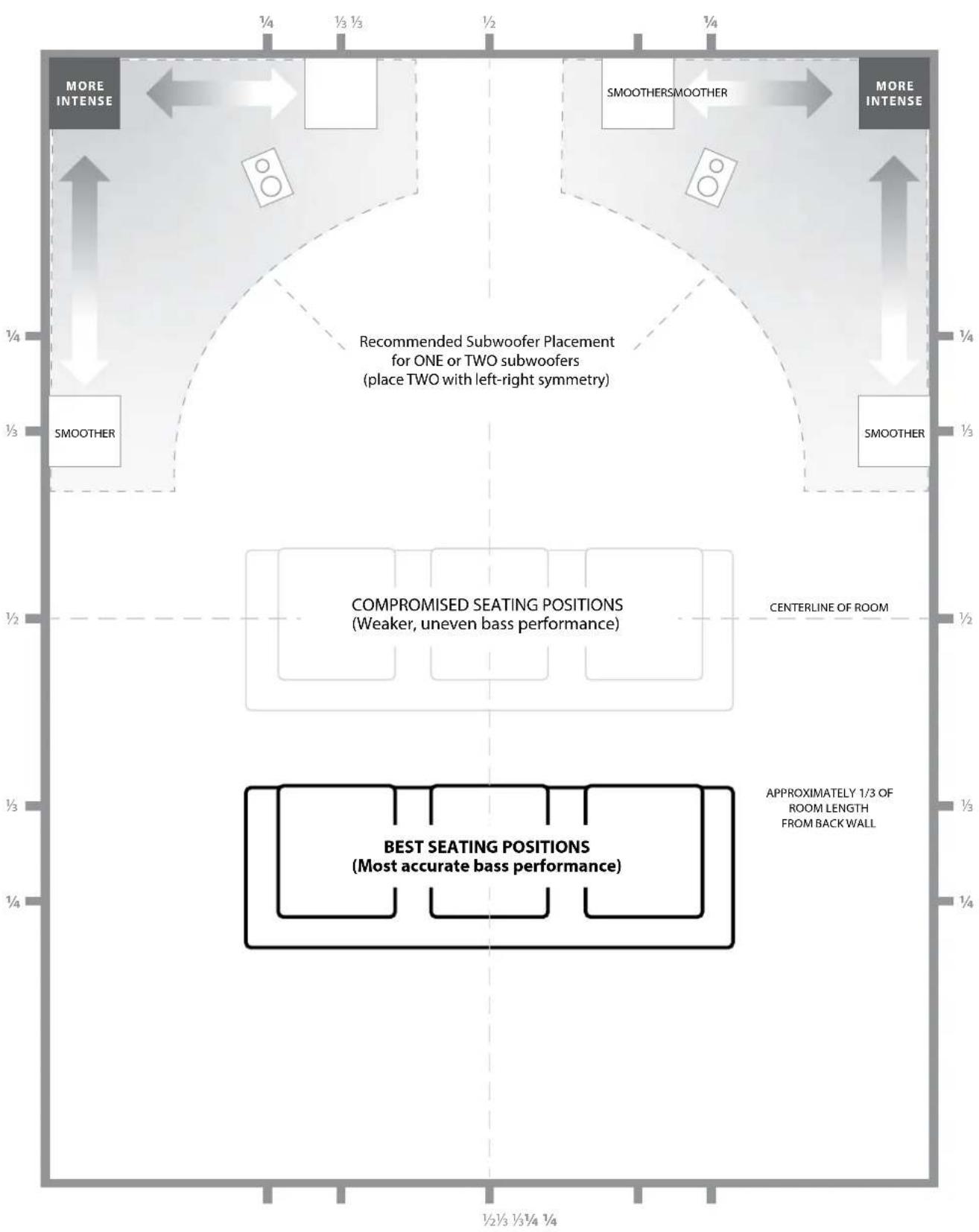
We recommend that you begin by placing your Fathom IWSv2 enclosure in the front of the room, near the front left or right speaker, but not directly in the corner of the room. Because the IWSv2 enclosures are built into the walls, you cannot move them later if the corner-loaded bass turns out to be too strong. Please refer to the following illustrations for further placement ideas.
We recommend that you avoid placing the Fathom IWSv2 enclosures near windows to prevent rattling and sound transmission to the outside world.

If you are planning to install your Fathom IWSv2 amplifier inside a cabinet, please refer to the guidelines on page 8.
Recommended Subwoofer Placement Options for One Fathom IWSv2 Enclosure
flowchart
graph TD
    A["MORE INTENSE"] --> B["SMOOTHER"]
    B --> C["SMOOTHERSMOOTHER"]
    C --> D["MORE INTENSE"]
    D --> E["BEST SEATING POSITIONS (Most accurate bass performance)"]
    E --> F["COMPROMISED SEATING POSITIONS (Weaker, uneven bass performance)"]
    F --> G["CENTERLINE OF ROOM"]
    G --> H["APPROXIMATELY 1/3 OF ROOM LENGTH FROM BACKWALL"]
    H --> I["Recommended Subwoofer Placement for ONE or TWO subwoofers (place TWO with left-right symmetry)"]
    I --> J["1/4"]
    I --> K["1/3"]
    I --> L["1/2"]
    I --> M["1/4"]
    style A fill:#f9f,stroke:#333
    style D fill:#f9f,stroke:#333
    style E fill:#ccf,stroke:#333
    style F fill:#cfc,stroke:#333
    style G fill:#fcc,stroke:#333
    style H fill:#cff,stroke:#333
    style I fill:#ffc,stroke:#333
    style J fill:#fcf,stroke:#333
    style K fill:#cff,stroke:#333
    style L fill:#ffc,stroke:#333
    style M fill:#cfc,stroke:#333
SPECIAL AMPLIFIER CONSIDERATIONS FOR RACK MOUNTING OR CUSTOM CABINET INSTALLATIONS
Fathom IWSv2 amplifiers are designed to be "built-in" friendly. All typically needed controls are located on the front panel. A Fathom IWSv2 amp can be easily integrated into an equipment rack or custom cabinetry by following a few simple guidelines.
- Allow adequate clear space around the Fathom IWSv2 amp's side-mounted heatsinks for adequate cooling. Also allow space behind the amp for connector clearance.
- The Fathom IWSv2 amp ships ready to be mounted in a standard equipment rack.
- The Fathom IWSv2 amplifier also includes table-top hardware. Special front-panel end covers that replace the rack ears and rubber feet are included with the IWSv2 amp. To use the amp on a table top, simply remove the hex screws that attach the rack ears and then install the covers. The rubber feet screw into threaded holes in the bottom of the amplifier case. WARNING: The rubber feet attach using M6-1.0 x 10mm screws. If lost or misplaced, only replace with the same type and length of screws. Using longer screws will cause damage to the internal circuit board.
- While the Fathom IWSv2 amp generally runs only warm during spirited operation, we do recommend that adequate heat vents are included in any custom cabinet which encloses the Fathom IWSv2 amp. A pair of 3 inch (7.5 cm) diameter vents near the bottom of the cabinet and near the top of the cabinet, will allow cool air to circulate over the heatsinks of your Fathom IWSv2 amp, keeping it cool and happy.
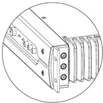
natural_image
Technical line drawing of a mechanical component with multiple spring-like elements and mounting holes (no text or symbols)Rack Ears

natural_image
Technical line drawing of a mechanical component with multiple spring-like elements and mounting holes (no text or symbols)End Covers
Using Two Fathom IWSv2 Enclosures
When using two Fathom IWSv2 boxes, try placement along the front wall near the front left and right speakers, or at the center points of opposing walls as shown at right.
Experimentation with listener placement is recommended to achieve the best results - the benefits can be substantial.
High-resolution measurements and professional system calibration are recommended for the best possible results & system performance.
Recommended Subwoofer Placement Options for Two Fathom IWSv2s
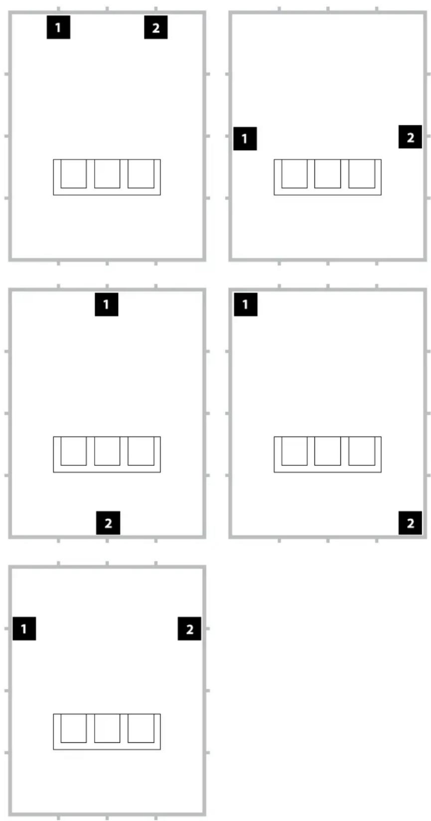
Recommended Subwoofer Placement Options for Three Fathom IWSv2s
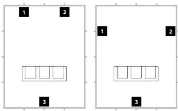
Recommended Subwoofer Placement Options for Four Fathom IWSv2s

Using Three or Four Fathom IWSv2 Enclosures
Research indicates that the smoothest bass response for a large listening area can be achieved using four subwoofers, placing one at the midpoint of each of the four walls (although using two or three subwoofers can be almost as good).
Experimentation with subwoofer and listener placement is recommended to achieve the best results – the benefits can be substantial.
High-resolution measurements and professional system calibration are recommended for the best possible results & system performance.
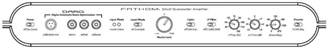
Front Control Panel
The labeled Figure below depicts the front control panel of a Fathom IWSv2 subwoofer.
![D.A.R.O. Page 13-14 Level Mode Page 14 Input Mode Page 14 Master Level Page 14 Lights Page 14 LP freq. (Hz) page 15 e.l.f. trim (dB) page 15 phase (deg.) page 16 Polarity page 16 Power page 12 Digital Automatic Wave Optimization Digital Automatic Wave Optimization Input Mode Level Mode Input Mode Level Mode Power Power Power Power Power Power Power Power Power Power Power Power Power Power Power Power Power Power Power Power Power Power Power Power Power Power Power Power Power Power Power Power Power Power Power Power Power Power Power Power Power Power Power Power Power Power Power Power Power Power Polarity s [100 mg] JL AUDIO.](/content/2026/03/582240/images/9483c6d1ab9da6c0c7b55389c7579a5eb9bca74c8d83c4e92771a583dc578db7.jpg)
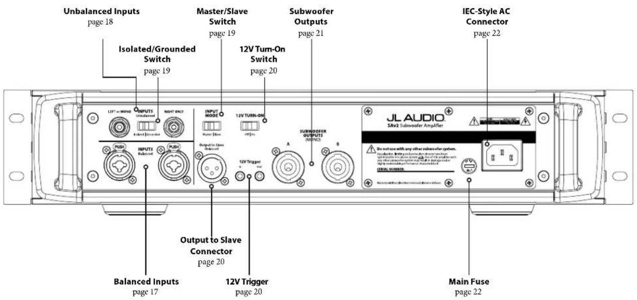
Rear Controls and Connectors
The labeled Figure below depicts the rear panel of a Fathom IWSv2 subwoofer.
FRONT PANEL CONTROLS IN DETAIL
Power Switch
The “Power” switch determines the operational readiness of the Fathom IWSv2 system and should be the only switch used to turn the Fathom IWSv2 amplifier on and off. Do not use a power strip switch, switched outlet or any other external switch as these may result in undesirable and potentially damaging transient pops. Do not unplug the Fathom IWSv2's AC power cord while the unit is turned on.
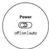
The power switch has three positions:
"off": The Fathom IWSv2's power amplifier is powered down. In this state, a negligible current draw will exist for operating the main power relays. All front panel lights are off.
“on”: The Fathom IWSv2 amp is fully powered at all times. Front panel lights are on unless they have been turned off via the “Lights” switch.
"auto": In this position, the Fathom IWSv2 amp can be activated by the following methods:
Signal Sensing: In this mode, the Fathom IWSv2 amp will power up when an audio signal is present at any of its inputs and will power down its internal amplifier when no signal has been detected at its inputs for thirty (30) minutes. When dormant, the Fathom IWSv2 will draw a very small amount of current (< 10 watts) to power its Signal-Sensing circuitry. Front panel lights will turn off when the Fathom IWSv2 powers down and light when the Fathom IWSv2 powers up (unless they have been turned off via the “Lights” switch).
Note: In the unlikely event that the Auto feature is not sensitive enough for a particular system, use a Y-cable adaptor to split the incoming signal into both RCA or XLR inputs on the Fathom IWSv2. This will increase the input sensitivity by 6 dB. Please be aware that if the Auto sensitivity is too high or if there is significant noise on the input cable, the Fathom IWSv2 may not turn off as desired. If this happens, remove the Y-cable adaptor or look for the noise source in the upstream components.
12VTrigger: Optionally, the Fathom IWSv2 amp can be activated using a 12V DC signal. To enable this mode, flip the "12V TURN-ON" switch located on the back panel (see page 20) to the "On" position. This setting overrides audio Signal-Sensing and will only turn on the Fathom IWSv2 amp when a 12V DC signal is present at its "12V Trigger – In" connection. When the 12V DC signal is removed, the Fathom IWSv2 amp will enter Standby mode immediately. Front panel lights will turn off when the Fathom IWSv2 powers down and light when the Fathom IWSv2 powers up (unless they have been turned off via the "Lights" switch).
Note: Whenever the Fathom IWSv2 amp is ON, its "12V Trigger – Out" output will be active, regardless of the "12V TURN-ON" switch's position. This allows you to control multiple Fathom IWSv2 amps using a single 12V trigger lead by daisy-chaining them together ("12V Trigger – Out" activates the "12V Trigger – In" of the next amp, etc.).


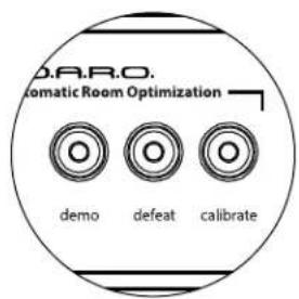
Digital Automatic Room Optimization (D.A.R.O.)
A powerful feature of the JL Audio Fathom IWSv2 subwoofers is their innovative Digital Automatic Room Optimization (D.A.R.O.) technology. This one-touch system includes 18 bands of digital equalization to eliminate the largest acoustic response peaks in your home theater at the main listening seat, greatly improving the in-room low-frequency response. Calibration of the D.A.R.O. system is fully automated. Please consult the next section of this manual for details on how to use the D.A.R.O. system.
Using the included JL Audio calibration microphone, the D.A.R.O. calibration procedure takes less than three minutes. In brief, you will connect the included microphone to the "Calibration Mic." input, press the Calibrate button, and then hold the microphone at ear height in your main listening seat during the test. A noise sequence will be played through the Fathom IWSv2 subwoofer, and the room response will be automatically measured, analyzed and equalized to eliminate the single largest acoustic room response peak at your listening seat. For detailed instructions on the D.A.R.O. setup procedure, refer to pages 29-30.
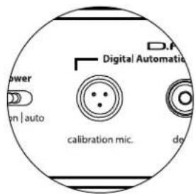
Calibration Mic. Input
This input is for connecting the supplied JL Audio calibration microphone to the Fathom IWSv2 subwoofer. Connect one end of the supplied cable to the microphone and the other end to this jack prior to using the D.A.R.O. system. The D.A.R.O. system is specifically calibrated to this microphone and its connection scheme is specific to the supplied microphone. The calibration sequence will not operate when a different microphone is connected or if no microphone is connected.
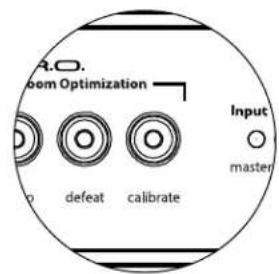
Demo Button
The Demo button triggers a 20 second long tone sequence that briefly demonstrates the sound of the Fathom IWSv2 subwoofer. The Demo function is useful for showcasing the output capability of the Fathom IWSv2 and to verify that the Fathom IWSv2 (or multiple Fathom IWSv2s) are operational during system troubleshooting.
The Demo button is also used (in combination) to clear (return to flat) the D.A.R.O. equalizer settings. To clear the D.A.R.O. settings & turn off the Calibrate light, press and hold the Demo button and then press the Defeat button. Please note that you must perform this button sequence quickly. If you hold the Demo button for more than 2 seconds without touching the Defeat button, the Demo tones will start. Should this happen, simply wait for the Demo sequence to end and try again.
Defeat Button
If “Demo” or “Calibrate” is pressed while the defeat function is active, “Defeat” is automatically canceled. No other front panel controls will alter the D.A.R.O. Defeat state. The Fathom IWSv2’s Defeat setting is stored in non-volatile memory and will not change even if power is disconnected.
The Defeat button is also used (in combination) to clear (return to flat) the D.A.R.O. equalizer settings. To clear the D.A.R.O. settings & turn off the Calibrate light, press and hold the Demo button and then press the Defeat button. Please note that you must perform this button sequence quickly. If you hold the Demo button for more than 2 seconds without touching the Defeat button, the Demo tones will start. Should this happen, simply wait for the Demo sequence to end and try again.
Calibrate Button
During the D.A.R.O. test sequence the Calibrate button's green LED will blink quickly to alert the user to two special conditions:
- "JL Audio Microphone NOT Connected": If you forget to connect the mic before trying to start a Calibration you will get this alert. Press the Calibrate button once to cancel the alert, connect the D.A.R.O. microphone, and try again.
- "Inappropriate Sound Level for D.A.R.O. Calibration": Since the D.A.R.O. sequence is completely automatic, this alert likely indicates a problem with the microphone. Press the Calibrate button once to cancel the alert. Ensure that the JL Audio microphone is properly connected and try again. For further help, please refer to Troubleshooting on page 33.
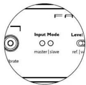
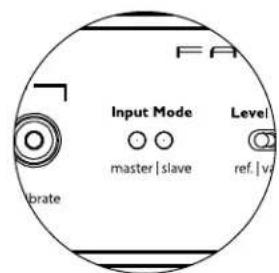
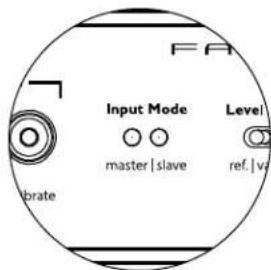
Input Mode Indicators
The Input Mode indicator LEDs show the input mode, either "Master" or "Slave", selected by the switch on the Fathom IWSv2's back panel (unless the "Lights" switch is set to "off"). For further details, see page 19.
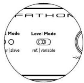
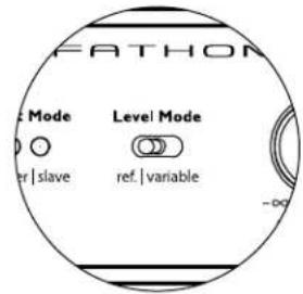
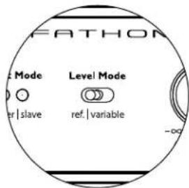
Level Mode
The two-position Level Mode switch allows you to select between the following modes:
"Reference" - In this mode, the Master Level control knob has no effect on the Fathom IWSv2's output level. Use this setting if you will primarily be controlling the subwoofer level via your receiver or preamplifier/processor. For those of us with small children or overenthusiastic teenagers, this mode of operation will prevent direct manipulation of the Master Level.
"Variable" - In this mode, the Master Level control knob determines the output level of the Fathom IWSv2 subwoofer. This mode is also useful when level matching the Fathom IWSv2 subwoofer to a pair of stereo speakers in a two-channel system.
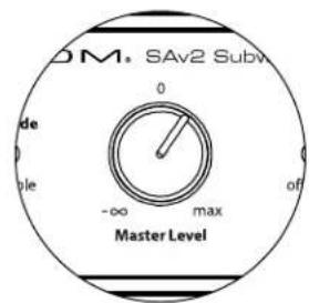
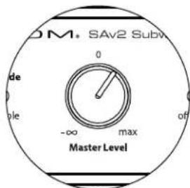
Master Level Knob
The Master Level Knob is used to control the output level of the Fathom IWSv2 when the Variable Level mode is selected on the front control panel.
When rotated fully counter clockwise, the Fathom IWSv2's output will be fully muted. When at the "0" or straight up position, the Variable gain level matches the Reference level setting. When turned fully clockwise, the Fathom IWSv2's output level is 15 dB higher than the Reference setting.
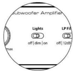
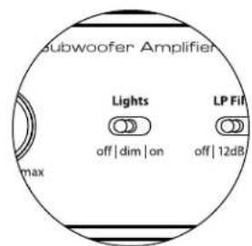
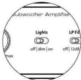
Lights
The “Lights” selector switch allows the user to select one of three indicator light modes.
"Off" turns off all of the front panel LED's at all times.
“Dim” sets all of the front panel LEDs to a low brightness level when the Fathom IWSv2 is turned on.
"On" sets all of the front panel LEDs to full brightness level when the Fathom IWSv2 is turned on.
IMPORTANT! WHEN TROUBLESHOOTING OR CALIBRATING THE D.A.R.O. FEATURE, MAKE SURE THAT THE "LIGHTS" SWITCH IS SET TO "DIM" or "ON."


IMPORTANT

radar
| Parameter | Value | |---|---| | Frequency (Hz) | 50 | | Current (Hz) | 70 | | Power (W) | 90 | | Current (W) | 100 | | Power (W) | 115 | | Current (W) | 130 | | Power (W) | -12 | | Current (W) | -8 | | Power (W) | -3 | | Current (W) | 0 | | Power (W) | 24dB |
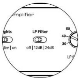
LP Filter
The Low Pass (LP) Filter selector switch determines the operating mode of the Fathom IWSv2's built-in low pass filter.
"Off" defeats the low pass filter, completely removing this circuit from the signal path.
“12 dB” sets the roll off slope of the low pass filter to a 12 dB per octave slope (Butterworth alignment).
“24 dB” sets the roll off slope of the low pass filter to a 24 dB per octave slope (Linkwitz-Riley alignment).
The 24 dB setting more aggressively attenuates high frequencies above the LP Frequency setting (see below). If you are using the Fathom IWSv2's built-in low pass filter, experiment with the LP Filter slope setting to achieve the best transition to your satellite speakers. If you prefer to use the filters and bass management features in your receiver or preamplifier, defeat the on-board filter by selecting the "Off" position.
If the Fathom IWSv2 enclosure is placed close to the listening position, it may be very easy to localize the sub's output. Experiment with the low pass filter to make the subwoofer less easy to localize.
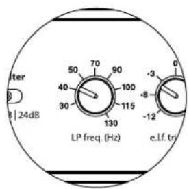
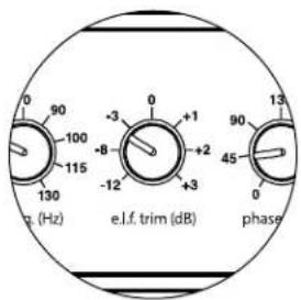
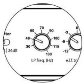
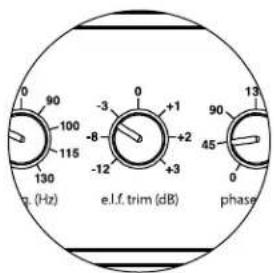
LP Freq
The Low Pass (LP) Frequency selector knob allows the user to choose the roll-off frequency of the Fathom IWSv2's internal low pass filter. The frequency is variable between 30 Hz (full counter-clockwise) to 130 Hz (full clockwise). This knob does not affect the input signal in any way if the LP Filter switch is set to "Off". 80 Hz is a commonly used filter frequency and usually serves as a good starting point for adjustments.
E.L.F. Trim
The Extreme Low Frequency (“e.l.f. trim”) knob allows the user to apply a certain amount of signal equalization at 23 Hertz (extremely low bass). At full counterclockwise rotation, the signal at 23 Hz is cut by 12 dB. At “0” the equalizer is set flat for zero contribution to the signal. At full clockwise rotation, the signal at 28 Hz is boosted by 3 dB.
The E.L.F. Trim feature is useful for tailoring the Fathom IWSv2's very low frequency output for your particular room. Adding some boost can make certain material more exciting. Using the cut function can help to compensate for room or boundary gain in the low frequencies. Room boundaries and the room's finite (limited) size naturally cause very low frequencies to be boosted relative to other parts of the signal. As such, using the E.L.F. Trim feature to cut the lowest frequencies can help to tame "bloat" or unnatural sounding low bass in small to medium sized rooms (and can also reduce unwanted vibrations in the room or throughout the house).
The E.L.F. function affects frequencies 2 to 3 times higher than the 23 Hz specification. This frequency tapering effect may reduce the overall output of the subwoofer and require the user to increase the Main Level control after adjusting the E.L.F. Trim.
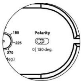
Polarity
The Polarity switch allows the user to select between normal (0 deg) and reversed (180 deg) signal polarity. The Polarity switch will primarily affect the small frequency range around the crossover point between your subwoofer and satellite speakers.
Unlike the Phase control, which effectively adds time delay, the Polarity switch produces an instantaneous reversal of the signal's amplitude peaks. For example, if at a given reference point a sine wave has an amplitude peak, by flipping the phase switch you instantly convert that peak into a trough or amplitude dip. Because the effect of the Polarity switch is immediate, it compliments the operation of the Phase control and cannot be replaced by it.
When placing your Fathom IWSv2 in the room, experiment with the Polarity switch before adjusting the “Phase” control. Either position of the Polarity switch may provide a smoother transition between your Fathom IWSv2 subwoofer and the satellite speakers. Use source material with good mid and upper bass content for evaluation.
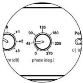
Phase
The Phase control knob allows the user to adjust the “timing” of the subwoofer output relative to the main speakers. The Phase control will primarily affect the small frequency range around the crossover point between your subwoofer and satellite speakers. The Phase control’s labels are referenced to 80 Hz since this is the most common crossover point between satellite speakers and a subwoofer. Phase settings between 0 degrees (full counter-clockwise rotation) and 270 degrees (full clockwise rotation) are possible.
Speaker, subwoofer, and listening seat positions vary greatly in home theater installations. Since physical positioning of speakers relative to the room boundaries and each other greatly affects the perceived quality of sound output, sometimes it is helpful to delay the subwoofer output. This is exactly what occurs when you turn the Phase control beyond 0 degrees.
Once your Fathom IWSv2 has been placed in your listening room to give you the smoothest overall sound and after you have determined the optimum “Polarity” switch position (see preceding section), experiment with the position of the Phase control. Using familiar source material with good mid and upper bass content, adjust the Phase control and listen for better defined mid-bass and a smoother transition between the subwoofer and satellite speaker systems. If no single setting sounds better than another, leave the Phase control at 0 degrees.
The Left and Right inputs on the Fathom IWSv2 are internally summed to a single mono channel. Since the Fathom IWSv2 is inherently a "mono" or single channel device, you can use the Left and Right inputs for the master Fathom IWSv2 and then distribute the summed mono signal to additional slave Fathom IWSv2s in the system.

IMPORTANT
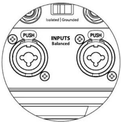
CONNECTING YOUR Fathom IWSv2 Balanced Inputs
If your home-theater receiver or preamplifier/processor provides balanced outputs, the Fathom IWSv2 amp's balanced inputs are the preferred connection. Balanced connections are used extensively in professional studios and sound reinforcement applications for a number of very good reasons. Besides ensuring proper grounding between components, balanced signal transmission is designed to cancel induced cable noise from the surrounding environment (particularly important with long cable runs). The bottom line is that your system will be far less likely to exhibit humming or other extraneous noises if you use balanced connections.
The Fathom IWSv2 subwoofers feature individual left and right balanced input connections with XLR "combo" jacks. These special jacks accept either a three-pin male XLR connector or a "tip-ring-sleeve" (TRS) 1/4-inch (6.3 mm) connector for compatibility with a wide range of equipment.
For systems with a mono subwoofer or "LFE" channel connection, only the jack labeled "Left or Mono" will be used. This applies to most modern multi-channel receivers and preamplifier/processors. Separate left and right input jacks are provided for systems without a dedicated mono subwoofer connection. This typically applies to two-channel audio equipment.
Appropriate balanced cables are available from your JL Audio dealer and are not included with the Fathom IWSv2.
Technical Notes:
- Do not use the balanced inputs with unbalanced signals via adaptors.
The unbalanced inputs of the Fathom IWSv2 are preferable in situations where only an unbalanced signal source is available. Balanced input impedance is 20 kohms. - Input connectors are configured according to Audio Engineering Society recommendations for balanced signal cables as follows:
XLR Connection
Pin 1: Shield
Pin 2: Positive
Pin 3: Negative
TRS connection:
Tip: Positive
Ring: Negative
Sleeve: Shield
IMPORTANT! IF YOUR RECEIVER OR PREAMPLIER/PROCESSOR DOES NOT HAVE XLR OR 1/4-INCH TRS BALANCED OUTPUTS, PLEASE REFER TO THE "UNBALANCED INPUTS" SECTION ON PAGE 18 FOR INPUT CONNECTION INFORMATION. DO NOT ATTEMPT TO CONNECT UNBALANCED OUTPUTS TO THE FATHOM IWSv2'S BALANCED INPUTS VIA ADAPTORS.
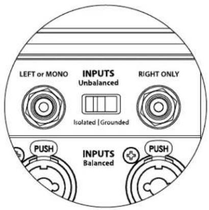
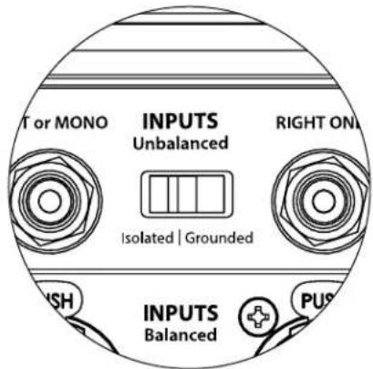
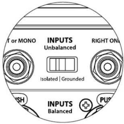
Unbalanced Inputs
The Fathom IWSv2 subwoofer amp features individual left and right unbalanced RCA-type input connectors. These are the most commonly used connectors for home audio applications and must be used if your receiver or preamplifier/processor does not provide balanced outputs. While unbalanced connections are not as noise-immune as a balanced connection, Fathom IWSv2 subwoofers employ ground isolation on the unbalanced inputs to minimize the possibility of noise in your system.
For systems with a mono subwoofer or "LFE" channel connection, only the RCA-type jack labeled "Left or Mono" will be used. This applies to most modern multi-channel receivers and preamplifier / processors. Separate left and right RCA-type input jacks are provided for systems without a dedicated mono subwoofer connection. This typically applies to two-channel audio equipment.
Technical Notes:
- When balanced outputs are not available on the signal source, you must use the RCA-type unbalanced inputs. Fathom IWSv2s feature ground isolation circuitry on the unbalanced inputs to minimize the likelihood of ground loop induced noise. Unbalanced input impedance is 50 kohms.
- Connections are industry-standard for unbalanced signal cables as follows:
RCA-type connection:
Tip: Positive
Sleeve: Negative
IMPORTANT! IF NOISE EXISTS AFTER CONNECTION, FATHOM IWSv2 AMPS ALLOW FOR GROUNDING OR ISOLATION OF THE UNBALANCED INPUTS. PLEASE REFER TO THE "INPUT MODE SWITCHES" SECTION ON PAGE 19 OF THIS MANUAL FOR FURTHER INFORMATION ON MINIMIZING NOISE.
IMPORTANT


IMPORTANT
Input Mode Switches:
Two switches are located on the rear panel to control unbalanced signal grounding and master/slave operation.
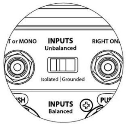
"Isolated / Grounded" Switch
The “Isolated / Grounded” Input Mode switch affects only the unbalanced RCA inputs and is designed to facilitate a quiet, hum-free connection to your audio or home theater system. This feature is included to deal with the signal grounding issues often encountered in home theater systems when several components from different manufacturers are interconnected.
The Fathom IWSv2 ships with this switch in the “Isolated” mode. If, with all system components connected and turned on (but no source material playing), you hear a continuous low-frequency hum through your Fathom IWSv2, flip this switch to the “Grounded” position and evaluate the difference in the noise level. Use whichever switch position provides the least hum or noise.
IMPORTANT! PLEASE NOTE THAT CHANGING ANY COMPONENT IN THE OPTIMIZED SYSTEM (RECEIVER, AMPLIFIER, DVD PLAYER, CABLE OR SATELLITE BOX, ETC.) COULD ALTER THE SIGNAL GROUNDING SCHEME AND CAUSE HUM TO APPEAR IN YOUR PREVIOUSLY QUIET SYSTEM. IF YOU ADD OR CHANGE AN UPSTREAM COMPONENT IN YOUR HOME THEATER SYSTEM, YOU MAY NEED TO REVISIT THIS INPUT MODE SETTING ON THE Fathom IWSv2 SUBWOOFER FOR OPTIMUM NOISE PERFORMANCE. CABLE & SATELLITE BOXES ARE PARTICULARLY TROUBLESOME IN THIS WAY.
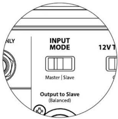
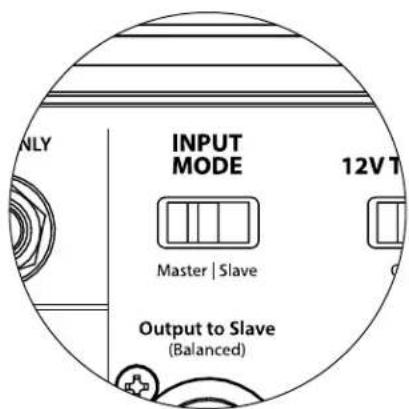
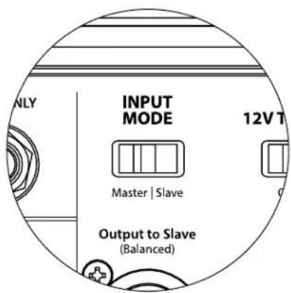
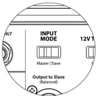
"Master / Slave" Switch
The Fathom IWSv2s are designed to easily accommodate the implementation of multiple subwoofers in your home theater system through a Master/Slave connection chain. This method allows you to utilize the signal processing features of one Fathom IWSv2 to centrally control multiple Fathom IWSv2s in the room. Master/Slave functionality also makes it possible for the D.A.R.O. system to optimize the response of a multiple subwoofer installation.
The Fathom IWSv2 ships with this switch in the "Master" position. If you are using a single Fathom IWSv2 you will use the "Master" position and you need not concern yourself with this section any further.
If your installation incorporates two or more Fathom IWSv2 amplifiers, you will designate one Fathom IWSv2 as the "Master" and all others in the system as "Slave" via the "Master/Slave" switch on the rear amplifier panel of each Fathom IWSv2. LED's on the front panel of the Fathom IWSv2 are provided to indicate whether the "Master" or "Slave" mode is selected for a given subwoofer.
From the Fathom IWSv2 operating in “Master” mode, the “Output to Slave” signal carries any signal processing selected on the Master Fathom IWSv2 (including the Master Level setting and D.A.R.O. processing) to further Fathom IWSv2s operating in “Slave” mode. “Slave” subwoofer signal processing and level controls will be inoperable. In this mode, the user does not have to worry about level, crossover, and other settings for the slave subwoofers.
Technical Notes:
- Selecting the “Slave” position defeats all user-definable signal processing and the master level control. Because of this, there are some special situations in which you may want to operate a single Fathom IWSv2 in “Slave” mode. If you are utilizing outboard signal processing and level-matching controls, activating the “Slave” mode will prevent anyone from affecting system parameters with the manual controls on the Fathom IWSv2.
IMPORTANT! PLEASE REFER TO THE "SYSTEM CONNECTION DIAGRAMS" ON PAGES 23-26 FOR MORE INFORMATION ON USING THE INPUT / OUTPUT CONNECTIONS.
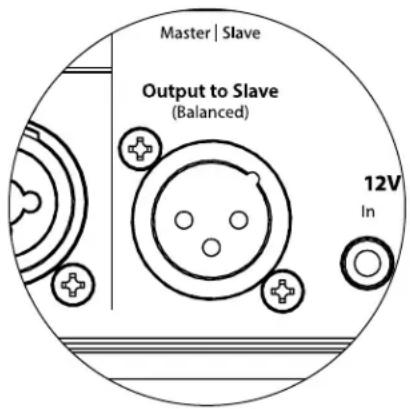
"Output to Slave" Connector
If you are operating more than one Fathom IWSv2 subwoofer in one home theater system, you will designate one Fathom IWSv2 as the Master (see page 19), and then feed signal from it to the remaining “Slave” Fathom IWSv2s via this balanced XLR output. The “Output to Slave” cable can be connected to the “Left or Mono” balanced XLR input on the next Fathom IWSv2. When a Fathom IWSv2 is in “Slave” Mode, its “Output to Slave” connection can be used to pass signal to further Fathom IWSv2s operating in “Slave” mode.
The "Output to Slave" connector is designed to be used as follows:
1) From the "Master" Fathom IWSv2's "Output to Slave" connector to the first "Slave" Fathom IWSv2's "Left or Mono" XLR balanced input.
2) From the first "Slave" Fathom IWSv2's "Output to Slave" connector to the second "Slave" Fathom IWSv2's "Left or Mono" XLR balanced input.
3) From the second “Slave” Fathom IWSv2’s “Output to Slave” connector to the third “Slave” Fathom IWSv2’s “Left or Mono” XLR balanced input. Etc, etc. (up to ten Fathom IWSv2s may be connected in this configuration). Appropriate balanced cables with XLR terminations are available from your JL Audio dealer and are not included with the Fathom IWSv2.
Technical Notes:
- The “Output to Slave” signal carries any signal processing selected on the Master Fathom IWSv2 (including the Master Level setting and D.A.R.O. processing) to further Fathom IWSv2s operating in “Slave” mode.
- From Fathom IWSv2s operating in “Slave” mode, the “Output to Slave” signal is an exact, buffered replica of the balanced input signal, making this method of signal distribution preferable to using Y-adapters or splitters.
- Use only shielded, connection cables with high quality XLR connectors for Master/Slave connection. Never use unbalanced cables with adaptors.
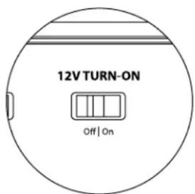
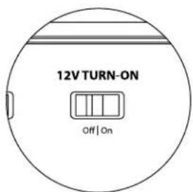
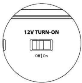
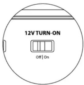
"12V Turn-On" Switch
This switch is used to enable the Fathom IWSv2 amp's 12V Trigger functionality. Refer to 12V Trigger on page 12 for more info. To activate, flip this switch to the "On" position with the front panel "Power" switch set to the "auto" position.
12V Trigger
Equipped with dual mini jacks, the Fathom IWSv2 amp can be activated using a 12V trigger signal (Input) and turn on another component (or additional Fathom IWSv2 amps) any time the Fathom IWSv2 amp is on (Output). Both jacks accept standard 1/8-inch (3.5 mm) plugs (not supplied), with +12V connected to the "tip" conductor and Ground connected to the ring and/or sleeve conductor(s). Refer to 12V Trigger on page 12 for more info.
IMPORTANT


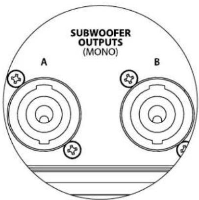
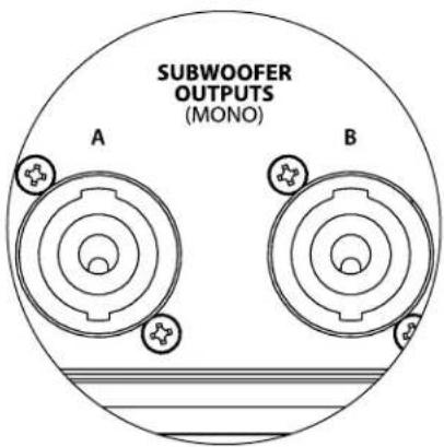
Subwoofer Outputs
The Fathom IWSv2 amp is equipped with a pair of Neutrik speakOn* jacks for speaker connections. Both jacks (labeled A & B) are configured for 2 wire termination (speaker + & speaker - ) and are connected in parallel, inside the Fathom IWSv2 amp, so you can use either output when connecting a single subwoofer.
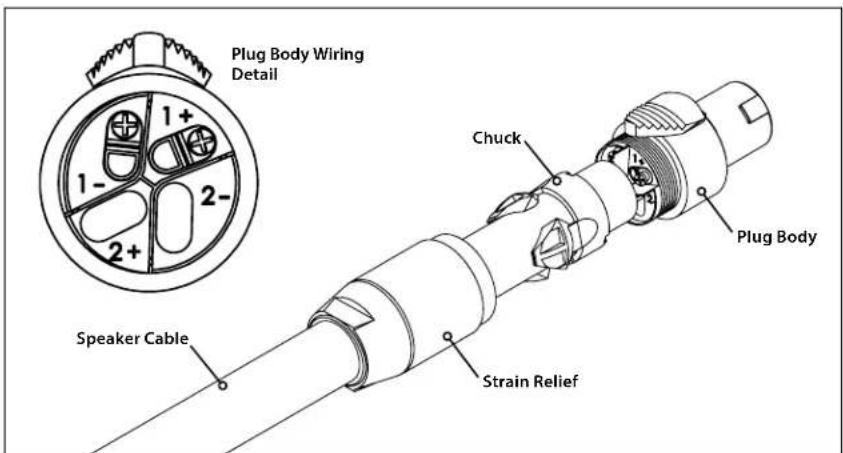
A pair of removable Neutrik speakOn® plugs (NL2FX) are supplied with the Fathom IWSv2 amp for making high-integrity connections. Each plug is keyed for insertion in the rear "SUBWOOFER OUTPUTS" jacks in one direction only. Once inserted, rotate the plug 1/8 turn clockwise to lock in place. To disconnect, slide the thumb latch back and rotate the plug 1/8 turn counter-clockwise to remove. Receptacles in each plug accept 12 AWG to 16 AWG speaker wire. Each wire attaches to the terminals marked "1-" and "1+" (shown below).
To attach wires, insert the speaker cable through the strain relief and chuck. Strip 12 inch (12 mm) of insulation from the end of each wire, then use a small Philips screwdriver to back out the set screws. Insert the bare wire into the receptacle, seating it firmly so that no bare wire is exposed. While holding each wire in place, tighten the set screw firmly, taking care not to strip the head of the screw.
Note: Use caution to ensure correct polarity and wire placement.
Slide the strain relief and chuck over the speaker cable, up to the plug body. Align the chuck with the recesses in the plug body and tighten the strain relief onto the plug body.
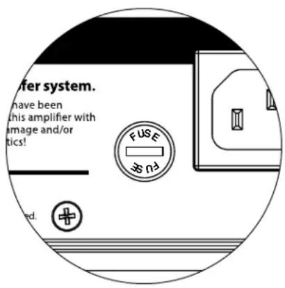
Main Fuse Holder
Located on the rear panel, next to the AC cord receptacle is the main fuse holder's cover. This small spring-loaded cap may be removed, allowing access to inspect or replace the main power fuse. If your AC outlet has power but the Fathom IWSv2 amps's lights do not come on, the main power fuse may be blown.
ToRemove - Unplug the AC power cord. Insert a small flathead screwdriver into the cap's slot and turn counter-clockwise slowly until the fuse holder is released. Once removed, the fuse can be inspected and, if necessary, replaced. Refer to the chart below for fuse values for your specific Fathom IWSv2 amp model.
ToReinstall - Note that the fuse holder's body is keyed to the opening and must be aligned to fit properly. Insert the fuse holder into the opening and gently turn clockwise (about 1/8 turn) to lock in place. Pressing the cap and feeling for the spring to compress will help to locate the correct position. Reconnect the AC power cord.
If the replacement fuse blows immediately after replacing a fuse replacement, the amplifier may require service. Please contact your Authorized JL Audio Retailer or Distributor.
| Fuse Specifications | ||
| Model Fuse Type | Fuse Size | |
| SAv2-1kW (120V version) | 0.25 x 1.25-inch, fast-acting 8A, 120V | |
| SAv2-1kW (240V version) | 5mm x 20mm, fast-acting 5A, 240V | |
| SAv2-2kW (120V version) | 0.25 x 1.25-inch, fast-acting | 12A, 120V |
| SAv2-2kW (240V version) | 5mm x 20mm, fast-acting 8A, 240V | |
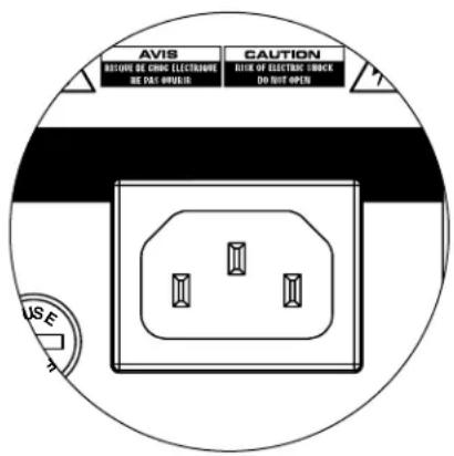
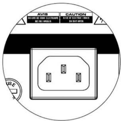
IEC-Style AC Connector
The IEC-style AC cord receptacle receives the heavy-gauge, 6 ft. (1.8 m) long, power cord included with your Fathom IWSv2 subwoofer. Amplifiers sold in different parts of the world are configured for each market's electrical system and include appropriate plugs on the power cords. Please note the voltage markings next to the AC Connector and make sure you are only powering the Fathom IWSv2 amp from a receptacle that matches these markings. Do not use any AC power cord other than the one supplied with the Fathom IWSv2.
The Fathom IWSv2 subwoofer is a very powerful device and can draw a lot of current. If too many components are connected with a Fathom IWSv2 subwoofer to one electrical outlet, you risk tripping a household circuit breaker during very demanding program material. If this happens, split the Fathom IWSv2 and other components between two AC electrical circuits. If possible, for maximum performance, dedicate an AC circuit to each Fathom IWSv2.
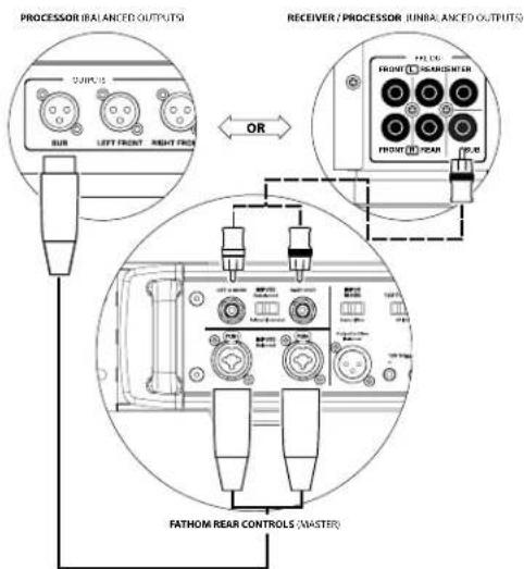
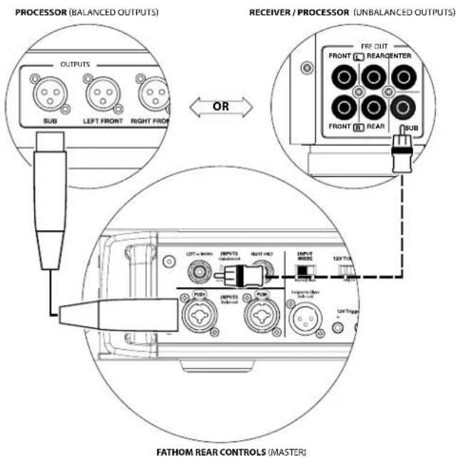
SYSTEM CONNECTION DIAGRAM 1: One Fathom IWSv2 to Home Theater Receiver or Home Theater Preamp/Processor
Most home theater receivers and preamp/processors provide a single (mono) subwoofer output. When connecting a mono subwoofer output to your Fathom IWSv2, you will only use the Fathom IWSv2's "Left or Mono" input.
Two connection types are available for connecting the Fathom IWSv2 to your home theater system: balanced (XLR or 1/4-inch TRS connector) and unbalanced (RCA-type connector). Balanced connections provide superior noise rejection and ensure proper grounding between components. If your receiver or processor has balanced outputs, we highly recommend that you use them.
In the connection diagram at left, balanced connections are shown as solid lines, unbalanced connections are shown dotted. You will only use one of these input connection methods (not both).

WARNING
WARNING! TURN OFF THE FATHOM IWSv2 AND ALL OTHER EQUIPMENT IN THE SYSTEM BEFORE MAKING OR CHANGING ANY CONNECTIONS!
WARNING! TURN OFF THE FATHOM IWSv2 AND ALL OTHER EQUIPMENT IN THE SYSTEM BEFORE MAKING OR CHANGING ANY CONNECTIONS!
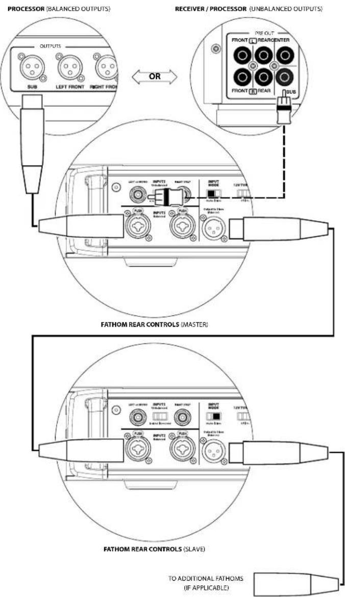
SYSTEM CONNECTION DIAGRAM 2: Multiple Fathom IWSv2s to Home Theater Receiver or Home Theater Preamp/Processor
To greatly simplify using multiple subwoofers in a single home theater system, Fathom IWSv2s incorporate a "Master/Slave" signal distribution system. This allows control of all the Fathom IWSv2s in a system from a single "Master" unit.
First, you will select one of the Fathom IWSv2 subwoofers as the "Master" via its upper "Input Mode" switch. Generally, you will designate the Fathom IWSv2 closest to the receiver/preamp as the master. In some cases; for example, when the control panel of certain units is difficult to access, you may prefer to designate the one which is easiest to access as the master.
Two connection types are available for connecting the master Fathom IWSv2 to your home theater system: balanced (XLR or 1/4-inch TRS connector) and unbalanced (RCA-type connector). Balanced connections provide superior noise rejection and ensure proper grounding between components. If your receiver or processor has balanced outputs, we highly recommend that you use them to connect to the Fathom IWSv2 designated as the master.
In the connection diagram at right, balanced connections are shown as solid lines, unbalanced connections are shown dotted. You will only use one of these input connection methods for the Fathom IWSv2 designated as the master (not both).
The remaining Fathom IWSv2s in the system will be configured as "Slave" units via their "Input Mode" switches. Using balanced XLR cables, you will connect the master Fathom IWSv2's "Output to Slave" to the "Left or Mono" balanced input of the first slave Fathom IWSv2. That slave unit's "Output to Slave" connector will feed the "Left or Mono" input of the next slave unit via another balanced XLR cable. Subsequent slave units will be connected in the same manner.

IMPORTANT
Connections between the "Master" and "Slave" Fathom IWSv2s and between "Slave" Fathom IWSv2s are via balanced XLR cables ONLY.

WARNING
SYSTEM CONNECTION DIAGRAM 3: One Fathom IWSv2 in Mono to Two-Channel Audio System
When connecting a Fathom IWSv2 (or multiple Fathom IWSv2s) in mono to a two-channel audio system you will use both the "Left or Mono" and the "Right" inputs. Summing circuitry in the Fathom IWSv2's input section will sum the stereo signals to mono.
We strongly recommend that you use a high-quality active crossover to divide your preamplifier's signals prior to connection to the Fathom IWSv2 and to the amplifier driving your main speakers. This will allow you to filter low frequencies out of the signals driving the main speakers, resulting in better performance.
If you are not using an active crossover and are comfortable running your main speakers full-range, you can split your preamplifier's output signals using appropriate Y-connectors in place of the active crossover shown in the diagram.
Two connection types are available for connecting the Fathom IWSv2 to your two-channel audio system: balanced (XLR or 1/4-inch TRS connector) and unbalanced (RCA-type connector). Balanced connections provide superior noise rejection and ensure proper grounding between components. If your preamplifier or active crossover offers balanced outputs, we highly recommend that you use them.
In the connection diagram at left, balanced connections are shown as solid lines, unbalanced connections are shown dotted. You will only use one of these input connection methods (not both).
NOTE: If desired, additional Fathom IWSv2s can be connected in "Slave" mode to the Fathom IWSv2 connected as shown on this diagram. See "Connection Diagram 2" on page 24 for slave connection explanation.
WARNING

WARNING! TURN OFF THE FATHOM IWSv2 AND ALL OTHER EQUIPMENT IN THE SYSTEM BEFORE MAKING OR CHANGING ANY CONNECTIONS!
WARNING! TURN OFF THE FATHOM IWSv2 AND ALL OTHER EQUIPMENT IN THE SYSTEM BEFORE MAKING OR CHANGING ANY CONNECTIONS!
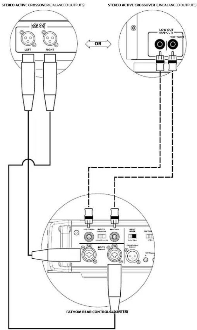
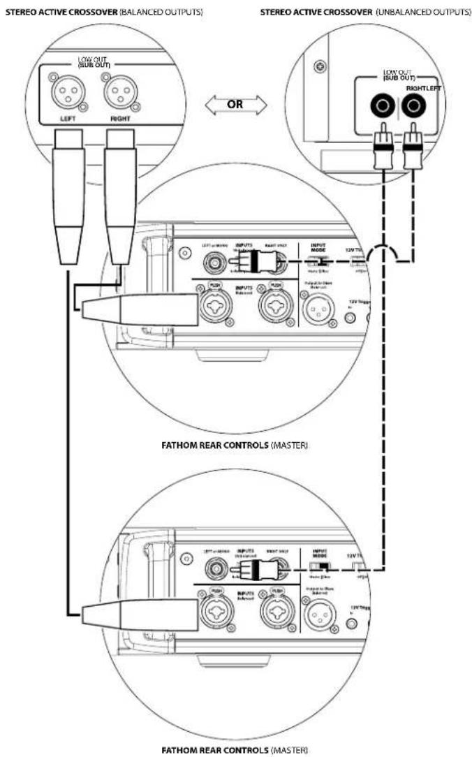
SYSTEM CONNECTION DIAGRAM 4: Two Fathom IWSv2s in Stereo to Two-Channel Audio System
When connecting two Fathom IWSv2s in stereo to a two-channel audio system you will only use the "Left or Mono" inputs of each Fathom IWSv2. The "Input Mode" switch on each Fathom IWSv2 will be set in the "Master" position.
We strongly recommend that you use a high-quality active crossover to divide your preamplifier's signals prior to connection to the Fathom IWSv2 and to the amplifier driving your main speakers. This will allow you to filter low frequencies out of the signals driving the main speakers, resulting in better performance.
If you are not using an active crossover and are comfortable running your main speakers full-range, you can split your preamplifier's output signals using appropriate Y-connectors in place of the active crossover shown in the diagram.
Two connection types are available for connecting the Fathom IWSv2s to your two-channel audio system: balanced (XLR or 1/4-inch TRS connector) and unbalanced (RCA-type connector). Balanced connections provide superior noise rejection and ensure proper grounding between components. If your preamplifier or active crossover offers balanced outputs, we highly recommend that you use them.
In the connection diagram at right, balanced connections are shown as solid lines, unbalanced connections are shown dotted. You will only use one of these input connection methods (not both).
NOTE: If desired, additional Fathom IWSv2s can be connected in "Slave" mode to each Fathom IWSv2 connected as shown on this diagram. See "Connection Diagram 2" on page 24 for slave connection explanation.

WARNING
RECOMMENDED SETUP PROCEDURES
- Preparation for Setup Process: 27-28
- Apply D.A.R.O: 29-30
- Level Setting: 30
- Polarity/Phase Adjustment: 31
- Adjust E.L.F. Trim: ....31
PREPARATION FOR SETUP PROCESS:
Please confirm the following system settings before beginning the setup process. This will ensure a neutral starting point and an effective setup of your subwoofer system.
On your Home Theater Receiver or Preamp/Processor:
Before beginning setup of your Fathom IWSv2 subwoofer system we recommend that you set your receiver or preamp/processor as follows:
1. Speaker Size
In the speaker setup menu of your receiver or preamp/processor, set up all of your high-frequency speakers as "small" with a crossover point of 80 Hz. This will send ALL bass to the Fathom IWSv2(s).
2. Speaker Distance
In the speaker setup menu, properly set all speaker distances to the primary listening seat, including the subwoofer's distance. Use a tape measure to determine these distances (time coherence is important.) If multiple Fathom IWSv2s are being used, average their distances to the primary listening seat and use that number to set the subwoofer distance.
3. Subwoofer Level
Set the subwoofer level in the receiver or preamp/processor "0" or its middle position.
4. Tone Controls / Equalizers
Set all tone controls to "0" and defeat all equalizer features.
On your Active Crossover or Bass Management Processor:
If you are using an active crossover or bass-management processor, we recommend that you set it as follows before beginning setup of your Fathom IWSv2 subwoofer system (please turn off all Fathom IWSv2s in the system prior to making these adjustments):
1. Low-Pass Filter Frequency
Select a low-pass filter frequency of 80 Hz (12dB/octave slope)
2. High-Pass Filter Frequency
Select a high-pass filter frequency of 80 Hz (12dB/octave slope)
3. Low-Pass (Subwoofer) Output Level
Set the subwoofer output level to "0" or its middle position.
On the Fathom IWSv2's Front Panel:
Please turn off the home theater receiver or preamp/processor to make these adjustments.
1. "Power"Switch
Flip each Fathom IWSv2's "Power" switch to the "On" position.
2. "Lights" Switch
Flip each Fathom IWSv2's "Lights" switch to the "On" position. If you don't see any lights on the front panel, you may have forgotten to plug the Fathom IWSv2 in or there may be a problem with the electrical circuit.
3. "Input Mode" Indicator Lights
If you are using a single Fathom IWSv2, confirm that its "Input Mode" indicator light is on the "Master" position. If not, you will need to access the "Input Mode" switch on the rear panel of the Fathom IWSv2. If you are using multiple Fathom IWSv2s in a Master/Slave configuration, confirm that the unit connected directly to your receiver or preamp/processor is indicating "Master" on its "Input Mode" lights and that all other units are indicating "Slave" on their "Input Mode" lights. If not, you will need to access the "Input Mode" switches on the rear panels of the Fathom IWSv2s.
4. "Level Mode" Switch
Flip the master Fathom IWSv2's "Level Mode" switch to the "REF" position.
5. "LP Filter" Switch
If your home theater receiver/processor is handling bass management (speakers set on "small") or if you are using an outboard crossover/bass-management processor, flip the master Fathom IWSv2's "LP Filter" switch to "OFF." If not, select the "12 dB" position.
6. "LP Freq. (Hz)" Knob
Rotate the "LP Freq." knob to the "80 Hz" position.
7. "e.l.f. trim (dB)" Knob
Rotate the "e.l.f. trim" knob to "0"
8. "Polarity"Switch
Flip the "Polarity" switch to "0".
9. "phase (deg.)" Knob
Rotate the "phase" knob to "0" degrees
10. D.A.R.O. Defeat Switch
Press the D.A.R.O. defeat switch so that the red light in the switch remains lit.
natural_image
Technical line drawing of a mechanical component with circular outline and mounting holes (no text or symbols)RECOMMENDED SETUP PROCEDURES (continued) Subwoofer System Setup:
Once you have set the controls on your home theater receiver or preamp/processor and on your Fathom IWSv2(s) to the settings recommended on pages 27-28, you are ready to begin setting up your Fathom IWSv2 for optimum performance.
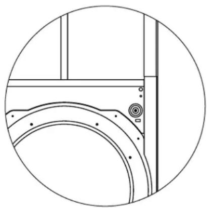
In some systems, the Fathom IWSv2 amplifier will be installed away from the listening environment. For these cases, the D.A.R.O. microphone cable will not be long enough to perform the Calibration.
To facilitate Calibration with the Fathom IWSv2 amplifier in the listening room, the Fathom IWSv2 subwoofer enclosure includes front-mounted speaker terminals (standard banana jacks - see figure). These terminals will allow the user to temporarily connect the amplifier to the enclosure for Calibration, even after the enclosure is permanently installed in the wall cavity.
If your system has a Master / Slave configuration, you only need to have the amplifier designated as Master located in the listening room. You must run a temporary XLR cable to the remotely located Slave unit(s).
1. Applying Digital Automatic Room Optimization (D.A.R.O.)
You are now ready to apply the power of JL Audio's exclusive Digital Automatic Room Optimization system. This system will measure the response of the subwoofer at your primary listening seat and apply a powerful 18-band equalizer to tame the peaks caused by room modes, resulting in smoother, more accurate bass performance. If you are using multiple Fathom IWSv2s in a master/slave configuration, you will only need to address the unit designated as "Master" to perform D.A.R.O. calibration for the entire subwoofer system. Note that all front-panel signal processing is defeated during D.A.R.O. calibration, regardless of the knob settings. Normal operation is restored once calibration is complete.
a) Set the Main Power switch to the "ON" position and be sure the Fathom IWSv2's indicator lights are switched "ON" via the "Lights" switch.
b) Remove the calibration microphone from its protective pouch and connect its cable to the mini-XLR jack on the Fathom IWSv2's front control panel.
NOTE: D.A.R.O. Calibration is only possible when the included JL Audio test microphone is plugged in to the Fathom IWSv2 front panel. The “Calibrate” feature is disabled with no microphone plugged in to prevent accidental loss of settings.
c) Connect the microphone to the other end of the mic cable and temporarily place the mic in the primary listening seat. If you have a microphone stand, you can place the microphone at head height and position in the primary listening seat.
d) On the Fathom IWSv2's control panel, press the "Calibrate" button. The green light on the "Calibrate" button will flash slowly, indicating that calibration will begin in 5 seconds.
IMPORTANT! MAKE SURE THE ROOM IS QUIET DURING D.A.R.O. CALIBRATION! TURN OFF ANY NOISY APPLIANCES NEAR THE LISTENING ROOM (DISHWASHERS, WASHING MACHINES, ETC.)
IT IS PARTICULARLY IMPORTANT TO TURN OFF AIR CONDITIONERS OR HEAT PUMPS DURING CALIBRATION. THESE FORCED-AIR-TYPE HVAC SYSTEMS CAN CREATE MODERATE LEVELS OF 15 – 20 HZ NOISE THAT MAY INTERFERE WITH CALIBRATION.
e) Within 5 seconds of pressing the “Calibrate” button, return to your primary listening seat and hold the microphone in your normal, seated head position at the approximate height of your ears.
f) A low rumbling noise sequence will be played through the subwoofer system that sounds like distant thunder. The sequence will last approximately 3 minutes. During this process, the D.A.R.O. system is taking a frequency response measurement at your seat and correcting the problems it finds. The D.A.R.O. system also compensates for any before & after level differences so that your subwoofer will have a similar perceived loudness after the calibration process. When D.A.R.O. is finished calibrating, the “Calibrate” button will light and stay on, indicating a successful calibration.
Should you wish to run a new calibration, simply repeat the steps above.
To clear the D.A.R.O.'s settings (i.e., return them to flat) & turn off the Calibrate light, press and hold the Demo button and then press the Defeat button. Please note that you must perform this button sequence quickly. If you hold the Demo button for more than 2 seconds without touching the Defeat button, the Demo tones will start. Should this happen, simply wait for the Demo sequence to end and try again. You can perform a new calibration by following the normal procedure outlined above.
2. Level Setting
Using familiar music or movie material with deep bass content, adjust the subwoofer level to blend with the other speakers using your receiver or preamp / processor's subwoofer level control. This method is more immune to tampering than using the Fathom IWSv2's "Master Level" knob (think toddlers or curious visitors).
In the unlikely event that the subwoofer level control in your receiver or preamp/processor cannot be turned up enough to level match the Fathom IWSv2, return that control to "0". Then, flip the Fathom IWSv2's "Level Mode" switch to "Variable" and with "0" as your reference point (REF mode gain and Variable "0" gain are identical) use the "Master Level" control to level match the subwoofer with the other speakers. MAKE NOTE OF THIS SETTING FOR FUTURE USE.
For more detailed information on your Fathom IWSv2's level setting controls, please refer to the "Level Mode" and "Master Level Knob" sections on page 14 of this manual.
3. Polarity and Phase Adjustment
It is often helpful to have a second person operating these controls so that you can easily hear the changes from the primary listening seat.

IMPORTANT
IMPORTANT

Listening to familiar source material (preferably music with good upper bass and midbass response), flip the "Polarity" switch from "0" to "180" and listen for differences. The correct setting will sound most natural with the best upper bass punch and articulation. If both sound similar, choose "0".
Once Polarity is set, use the same music material to audition different "Phase" control settings and choose the one that further enhances the upper and midbass response. If you can't hear a difference, set the control to "0."
4. Extreme Low Frequency (e.l.f.) Trim
Use the “e.l.f. trim” control to adjust the extreme low bass extension of the Fathom IWSv2. This control allows -12 dB of cut or +3 dB of boost at 24 Hertz and is particularly useful when using a Fathom IWSv2 (or two) in a small to medium sized home theater. Since smaller enclosed spaces help to boost the level of the lowest bass frequencies, smaller theaters can be overwhelmed by the strong low-bass output of the Fathom IWSv2 subwoofer. This can create a “thick” or “bloated” character in the lower bass region. Turning down the “e.l.f. trim” knob cuts the extreme low bass level and alleviates this condition. Feel free to experiment and listen to a variety of demanding material until you find the best match for your room and your tastes.
Your Fathom IWSv2 is now optimized for maximum bass performance at your listening seat. Congratulations!

IMPORTANT
IMPORTANT! WRITE DOWN ALL SETTINGS PERFORMED IN STEPS 2-4 FOR FUTURE REFERENCE.

IMPORTANT
IMPORTANT! IF YOU MOVE YOUR PRIMARY LISTENING SEAT IN THE FUTURE, YOU WILL NEED TO RUN D.A.R.O. AGAIN. ANY PARTICULAR CALIBRATION IS UNIQUE TO THAT PARTICULAR SUBWOOFER POSITION AND LISTENING SEAT POSITION COMBINATION. SIMPLY FOLLOW THE STEPS ABOVE TO CREATE A NEW CALIBRATION CURVE.
FREQUENTLY ASKED QUESTIONS
Is the Fathom IWSv2 magnetically shielded?
Fathom IWSv2 subwoofers are not magnetically shielded. To avoid magnetic distortion with certain television types, place the Fathom IWSv2 at least 3-4 feet (1 - 1.5m) from your screen.
Will my electric bill be high if I leave the Fathom IWSv2 in "Auto" mode?
When in “Auto” mode, the Fathom IWSv2 amplifier is only powered up when a significant signal is detected on the inputs. When powered down, only “housekeeping” circuits remain on, which draw negligible amounts of power from the wall (less than 10 watts).
Should I unplug my subwoofer during a thunderstorm or extended absence?
YES. You should unplug your Fathom IWSv2 during (or before) thunderstorms. This will prevent any possible damage from voltage spikes due to lightning. In these conditions, it's a good idea to unplug all of your audio / video components. If you are going to be away from home for several days, it is also a good idea to unplug your home theater components to prevent damage from unexpected storms or power line conditions.
TROUBLESHOOTING
No sound from the subwoofer.
- Verify that Fathom IWSv2 amp is plugged in, turned "ON" & that front panel lights are "ON". If the Fathom IWSv2 amp will not power up, check the circuit breaker that feeds its outlet.
- If the Fathom IWSv2 amp is configured to automatically turn "ON" via Signal Sensing mode, make sure the "12V TURN-ON" switch is set to "Off".
- Test subwoofer using DEMO button on front panel of amp- if sub emits demo tones the subwoofer's internal circuitry is fine and an input problem is likely. Check the input cable connections at the Fathom IWSv2 amp and at the receiver/preamp/processor.
- Verify that your receiver's subwoofer settings have not changed.
- If your other speakers play, but the Fathom IWSv2 does not, try changing the cable that connects the Fathom IWSv2 to the system.
- If the problem persists, call your dealer or JL Audio Technical Support for assistance.
The bass level has changed.
- Make sure your level settings (on the Fathom IWSv2 amp and in your receiver/preamp/processor) have not changed.
- If you are using the Fathom IWSv2's "Master Level" knob to set the subwoofer level, confirm that the "Level Mode" switch is set to "Variable".
- Verify the position of the ELF Trim knob.
Hums or other unusual noises from your Fathom IWSv2
- See "Input Mode Switches" section on page 19 of this manual, especially if any upstream components, cables, etc., have recently changed.
- Turn off the Fathom IWSv2, disconnect all its input and output signal cables, turn the Fathom IWSv2 back on. If the noise disappears, the noise is being caused elsewhere in your system - reconnect cables one at a time to help locate the problem.
Bass sounds "muddy" or "too heavy".
- Try decreasing the 24 Hertz level using the ELF Trim control. Muddy bass can sometimes be caused by too much low frequency output in a moderately sized room.
- Decrease the overall subwoofer level.
- Verify your receiver's subwoofer settings.
- Try a different main listening seat location. Changing your seating location can have a HUGE effect on how your system sounds. See the placement discussion on pages 6-10 of this manual.
D.A.R.O. Calibration attempt gives fast blinking Calibrate light
- Be sure that the included JL Audio Microphone is properly plugged into the front panel jack. Calibration will ONLY proceed with the JL Audio microphone connected. Connecting any other mic will cause the calibration to fail.
- If calibration fails with the JL Audio microphone properly connected, try running calibration again with the microphone placed \~ 6 feet away from the Fathom IWSv2 speaker enclosure. If calibration fails again, the microphone or microphone cable is bad and will need to be replaced. Contact JL Audio Customer Service.
FATHOM IWS
FEATURES
Unbalanced Inputs:
Stereo or Mono (two RCA jacks - Input Impedance of 50k Ohms)
Balanced Inputs:
Stereo or Mono (two female XLR jacks - Input Impedance of 20k Ohms)
Output To Slave:
Balanced (one male XLR jack)
Speaker Outputs:
Neutrik speak-On° 2-Pole Connectors (uses Neutrik part: NL2FX)
Input Modes:
Master or Slave
Level Modes:
Reference (fixed gain) or Variable from full mute to +15dB over reference gain
Power Modes:
Off, On or Automatic
(Signal-Sensing or 12V Trigger)
Light Modes:
Off, On or Dim
Low Pass Filter Mode:
Off, 12 dB per octave or 24 dB per octave
Low Pass Filter Cutoff Frequency:
Variable from 30 Hz - 130 Hz
Polarity:
0 or 180 degrees
Phase:
Variable from 0 - 270 degrees
E.L.F. Trim:
Variable from -12 dB to +3 dB at 23 Hz
Digital Automatic Room Optimization (D.A.R.O.):
Automatic, 18-band equalizer with included laboratory-grade calibration microphone, defeatable.
12V Trigger Output Capacity:
| Specifications | IWSv2-SYS-113Fathom IWSv2 home subwoofer | IWSv2-SYS-213Fathom IWSv2 home subwoofer |
| Enclosure Type: | Single Sealed Enclosure | Two Sealed Enclosures |
| Driver(s): | 13.5-inch(nominal diameter) | 13.5-inch (nominal diameter)in each of two enclosures |
| Frequency Response (anecholic): | 26 Hz - 101 Hz (+/- 1.5 dB)3dB at 25 Hz / 112 Hz10dB at 22 Hz / 150 Hz | 26 Hz - 101 Hz (+/- 1.5 dB)3dB at 25 Hz / 112 Hz10dB at 22 Hz / 150 Hz |
| Effective Piston Area: | 98.26 sq. in. / 0.0634 sq. m. | 196.51 sq. in. / 0.1268 sq. m. |
| Effective Displacement: | 147.3 cu. in. (2.41 liters) | 294.6 cu. in. (4.82 liters) |
| Amplifier Power: | 1000 watts RMS short-term 2000 watts RMS short-term | |
| Grille Dimensions: (H) Height x (W) Width | 17.64 inches x 17.14 inches448 mm x 435 mm | |
| Wall Opening Dimensions: (W) Width x (H) Height | 16 inches x 16.5 inches406 mm x 419 mm | |
| Amplifier Dimensions: (H) Height x (W) Width x (D) DepthHeight Dimensions DO NOT include feet. | 3.5 in. x 17.4 in. x 17.9 in.89 mm x 442 mm x 455 mm | |
| Amplifier Net Weight: | 35 lbs. (15.9 kg) 43 lbs. (19.5 kg) | |
| Cabinet Finish: | Black Texture Coated | Black Texture Coated |
| Grille Finish: | White (paintable) | |
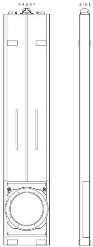
natural_image
Technical line drawing of a vertical cylindrical device with front and side views (no text or symbols)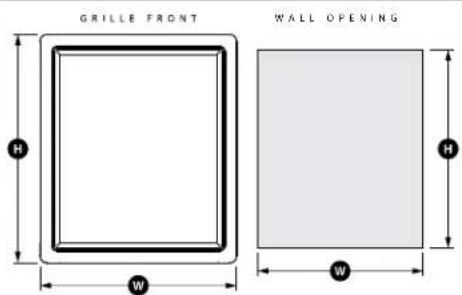

"JL Audio", "Fathom", and the JL Audio logo are registered trademarks of JL Audio, Inc.
©2022 JL Audio, Inc. • For more detailed information please visit us online at www.jlaudio.com. Product images shown are for illustrative purposes only and may differ from the actual product. Due to continuous product development, all specifications are subject to change without notice.
www.jlaudio.com
10369 North Commerce Parkway · Miramar, Florida · 33025 · USA

JLAUDIO®
DÉCLARATION DE CONFORMITÉ FCC
natural_image
Technical line drawing of a mechanical component with multiple spring-like elements and mounting holes (no text or symbols)Équerres de rack

natural_image
Technical line drawing of a mechanical component with multiple slots and mounting holes (no text or symbols)Caches de finition


IMPORTANT


Filtre passe-bas
IMPORTANT


IMPORTANT


natural_image
Technical line drawing of a mechanical assembly with circular outline (no text or symbols)PROCÉDURES DE RÉGLAGE RECOMMANDÉES (suite)
natural_image
Technical line drawing of a vertical cylindrical device with labeled sections 'AVANT' and 'COTE', showing internal components and mounting points (no text or symbols beyond labels)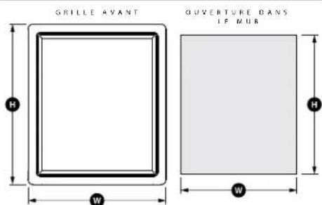

natural_image
Technical line drawing of a mechanical component with multiple spring-like elements and mounting holes (no text or symbols)natural_image
Technical line drawing of a mechanical component with multiple spring-like elements and mounting holes (no text or symbols)CONTROLES DEL PANEL FRONTAL EN DETALLE


radar
| Parameter | Value | |---|---| | Frequency (Hz) | 50 | | Range (Hz) | 70 | | Range (Hz) | 90 | | Range (Hz) | 100 | | Range (Hz) | 115 | | Range (Hz) | 130 | | e.l.f. tr | -3 | | e.l.f. tr | -8 | | e.l.f. tr | -12 | | Power (W) | 24 dB
Filtro LP
IMPORTANTE


IMPORTANTE

Salidas a subwoofer
Portafusible principal

2. Interruptor "Lights"
4. Interruptor "Level Mode"
6. Perilla "LP freq. (Hz)"
10. Interruptor "defeat" de DARO
natural_image
Technical line drawing of a mechanical assembly with circular outline (no text or symbols)Concentric Tube Suspension
Plateau-Reinforced Spider Attachment
High-Damping Feedback Circuit
natural_image
Technical line drawing of a mechanical component with multiple spring-like elements and mounting holes (no text or symbols)Montagewinkel

natural_image
Technical line drawing of a mechanical component with multiple spring-like elements and mounting holes (no text or symbols)Endabdeckungen


Digital Automatic Room Optimization (D.A.R.O.)

WICHTIG

LP-Filter
WICHTIG


WICHTIG

Subwoofer-Ausgänge
10. D.A.R.O. Defeat-Schalter
natural_image
Technical line drawing of a mechanical assembly with circular outline (no text or symbols)Digital Automatic Room Optimization (D.A.R.O.):
natural_image
Technical line drawing of a vertical cylindrical device with front and side views (no text or symbols)
TECNOLOGIE JL AUDIO INCLUSE NEI SUBWOOFER Fathom IWSv2
natural_image
Technical line drawing of a mechanical component with multiple spring-like elements and mounting holes (no text or symbols)Supporti per rack
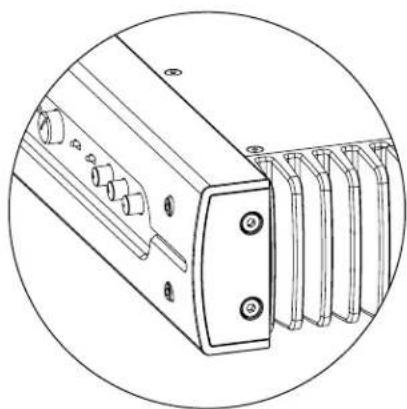
natural_image
Technical line drawing of a mechanical component with multiple spring-like elements and mounting holes (no text or symbols)Coperture terminali


Digital Automatic Room Optimization (D.A.R.O.)
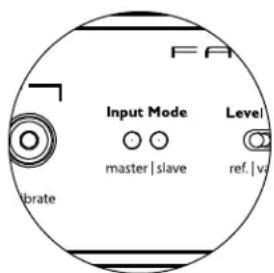
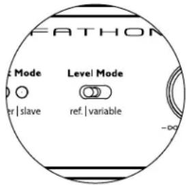
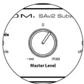
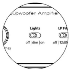

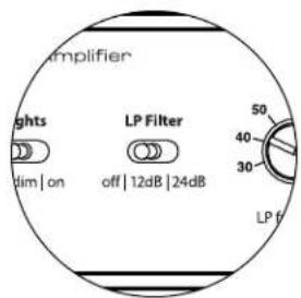
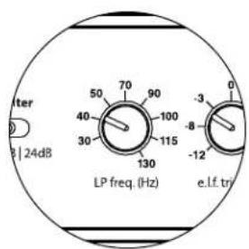
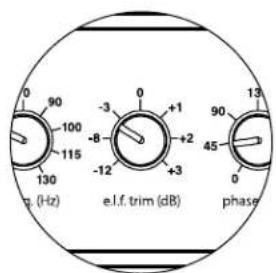
Filtro PB
IMPORTANTE

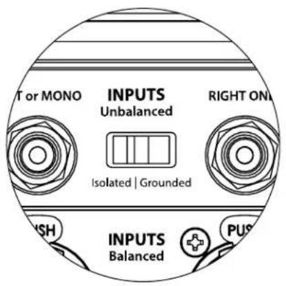

IMPORTANTE
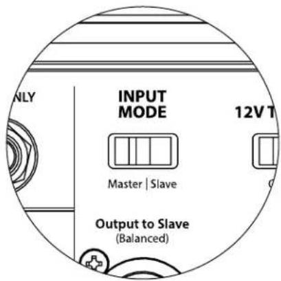
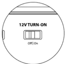
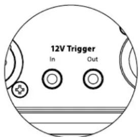

Uscite subwoofer

SCHEMA DI COLLEGAMENTO DELL'IMPIANTO 1:
Sul pannello anteriore del Fathom IWSv2:
3. Spie "Input Mode"
6. Manopola "LP Freq. (Hz)"
natural_image
Technical line drawing of a mechanical assembly with circular outline (no text or symbols)4. E.L.F. (Extreme Low Frequency) Trim
Digital Automatic Room Optimization (D.A.R.O.):
natural_image
Technical line drawing of a mechanical component with multiple circular slots and mounting holes (no text or symbols)机架耳
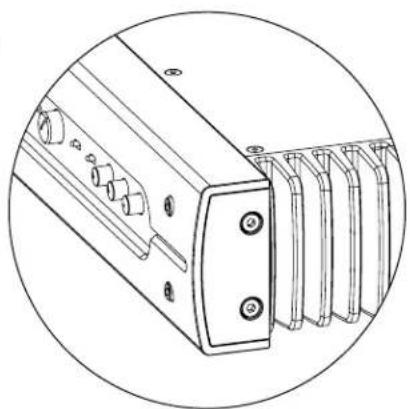
natural_image
Technical line drawing of a mechanical component with multiple slots and mounting holes (no text or symbols)端盖


数字化自动房间优化(D.A.R.O.)
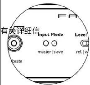

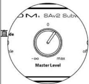
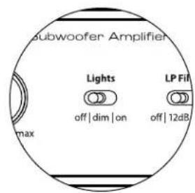

重要


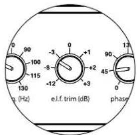
低通滤波器
重要

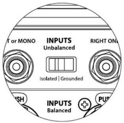

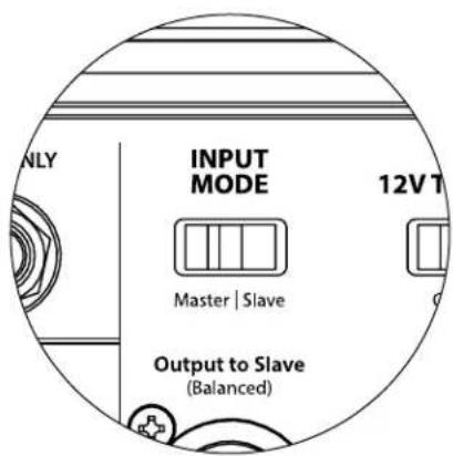
输入模式开关:

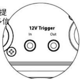
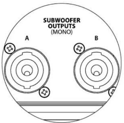
超低音音响输出

系统连接图 1:
natural_image
Technical line drawing of a mechanical assembly with circular outline (no text or symbols)推荐设置流程(续)
超低音音响系统设置:
natural_image
Technical line drawing of a vertical cylindrical device with internal components and mounting holes (no text or symbols)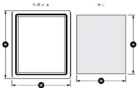
- IMPORTANT SAFETY INSTRUCTIONS
- CAUTION
- FCC COMPLIANCE STATEMENT
- TABLE OF CONTENTS
- INTRODUCTION
- JL AUDIO TECHNOLOGIES INCLUDED IN Fathom IWSv2 SUBWOOFERS
- DMA-Optimized Motor System
- Concentric Tube Suspension
- Floating-Cone™ Attach Method
- Plateau-Reinforced Spider Attachment
- High-Damping Feedback Circuit
- PRODUCT OVERVIEW
- PACKAGE CONTENTS
- PLACING YOUR FATHOM IWSV2 CABINETS IN YOUR LISTENING ROOM:
- SPECIAL AMPLIFIER CONSIDERATIONS FOR RACK MOUNTING OR CUSTOM CABINET INSTALLATIONS
- Using Two Fathom IWSv2 Enclosures
- Using Three or Four Fathom IWSv2 Enclosures
- Front Control Panel
- Rear Controls and Connectors
- FRONT PANEL CONTROLS IN DETAIL
- Power Switch
- The power switch has three positions:
- Digital Automatic Room Optimization (D.A.R.O.)
- Calibration Mic. Input
- Demo Button
- Defeat Button
- Calibrate Button
- Input Mode Indicators
- Level Mode
- Master Level Knob
- Lights
- LP Filter
- LP Freq
- E.L.F. Trim
- Polarity
- Phase
- CONNECTING YOUR Fathom IWSv2 Balanced Inputs
- Technical Notes:
- XLR Connection
- TRS connection:
- Unbalanced Inputs
- RCA-type connection:
- Input Mode Switches:
- "Isolated / Grounded" Switch
- "Master / Slave" Switch
- "Output to Slave" Connector
- The "Output to Slave" connector is designed to be used as follows:
- "12V Turn-On" Switch
- 12V Trigger
- Subwoofer Outputs
- Note: Use caution to ensure correct polarity and wire placement.
- Main Fuse Holder
- IEC-Style AC Connector
- FUS
- SYSTEM CONNECTION DIAGRAM 1: One Fathom IWSv2 to Home Theater Receiver or Home Theater Preamp/Processor
- SYSTEM CONNECTION DIAGRAM 2: Multiple Fathom IWSv2s to Home Theater Receiver or Home Theater Preamp/Processor
- IMPORTANT
- WARNING
- SYSTEM CONNECTION DIAGRAM 3: One Fathom IWSv2 in Mono to Two-Channel Audio System
- SYSTEM CONNECTION DIAGRAM 4: Two Fathom IWSv2s in Stereo to Two-Channel Audio System
- RECOMMENDED SETUP PROCEDURES
- PREPARATION FOR SETUP PROCESS:
- On your Home Theater Receiver or Preamp/Processor:
- Speaker Size
- Speaker Distance
- Subwoofer Level
- Tone Controls / Equalizers
- On your Active Crossover or Bass Management Processor:
- Low-Pass Filter Frequency
- High-Pass Filter Frequency
- Low-Pass (Subwoofer) Output Level
- On the Fathom IWSv2's Front Panel:
- "Power"Switch
- "Lights" Switch
- "Input Mode" Indicator Lights
- "Level Mode" Switch
- "LP Filter" Switch
- "LP Freq. (Hz)" Knob
- "e.l.f. trim (dB)" Knob
- "Polarity"Switch
- "phase (deg.)" Knob
- D.A.R.O. Defeat Switch
- RECOMMENDED SETUP PROCEDURES (continued) Subwoofer System Setup:
- Applying Digital Automatic Room Optimization (D.A.R.O.)
- Level Setting
- Polarity and Phase Adjustment
- Extreme Low Frequency (e.l.f.) Trim
- FREQUENTLY ASKED QUESTIONS
- Is the Fathom IWSv2 magnetically shielded?
- Will my electric bill be high if I leave the Fathom IWSv2 in "Auto" mode?
- Should I unplug my subwoofer during a thunderstorm or extended absence?
- TROUBLESHOOTING
- No sound from the subwoofer.
- The bass level has changed.
- Hums or other unusual noises from your Fathom IWSv2
- Bass sounds "muddy" or "too heavy".
- D.A.R.O. Calibration attempt gives fast blinking Calibrate light
- FATHOM IWS
- FEATURES
- Unbalanced Inputs:
- Balanced Inputs:
- Output To Slave:
- Speaker Outputs:
- Input Modes:
- Level Modes:
- Power Modes:
- Light Modes:
- Low Pass Filter Mode:
- Low Pass Filter Cutoff Frequency:
- Polarity:
- Phase:
- E.L.F. Trim:
- Digital Automatic Room Optimization (D.A.R.O.):
- 12V Trigger Output Capacity:
- JLAUDIO®
- DÉCLARATION DE CONFORMITÉ FCC
- Filtre passe-bas
- PROCÉDURES DE RÉGLAGE RECOMMANDÉES (suite)
- CONTROLES DEL PANEL FRONTAL EN DETALLE
- Filtro LP
- Salidas a subwoofer
- Portafusible principal
- Interruptor "Lights"
- Interruptor "Level Mode"
- Perilla "LP freq. (Hz)"
- Interruptor "defeat" de DARO
- LP-Filter
- Subwoofer-Ausgänge
- D.A.R.O. Defeat-Schalter
- TECNOLOGIE JL AUDIO INCLUSE NEI SUBWOOFER Fathom IWSv2
- Filtro PB
- Uscite subwoofer
- SCHEMA DI COLLEGAMENTO DELL'IMPIANTO 1:
- Sul pannello anteriore del Fathom IWSv2:
- Spie "Input Mode"
- Manopola "LP Freq. (Hz)"
- E.L.F. (Extreme Low Frequency) Trim
- 数字化自动房间优化(D.A.R.O.)
- 低通滤波器
- 输入模式开关:
- 超低音音响输出
- 系统连接图 1:
- 推荐设置流程(续)
- 超低音音响系统设置:
Brand : JL Audio
Model : Fathom IWSv2SYS213
Category : Subwoofer