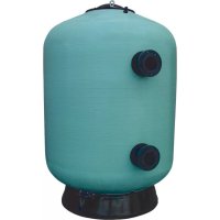
Oslo - Water filter ASTRALPOOL - Free user manual and instructions
Find the device manual for free Oslo ASTRALPOOL in PDF.



| Product type | Sand filter for swimming pool |
| Brand | AstralPool |
| Model | Oslo |
| Usage | Filtration of residential or public swimming pool water |
| Tank material | Polyester resin and fiberglass |
| Filter diameter | From 1050 mm to 3000 mm depending on model |
| Maximum allowable pressure | Indicated on the label (do not exceed) |
| Operating temperature | Ambient temperature (indicated on the label) |
| Filter media | Sand, sand + anthracite or multi-layer |
| Main functions | Filtration, backwash, rinse, drain, closed |
| Number of valves | 4-valve or 5-valve version |
| Accessories included | Pressure gauge, selector valves, diffuser, collector, supports |
| Maintenance | Regular backwash, rinse, periodic change of filter media |
| Cleaning | With soapy water, without solvents |
| Safety | Do not exceed max pressure, bleed air, protect from frost, stop pump before intervention |
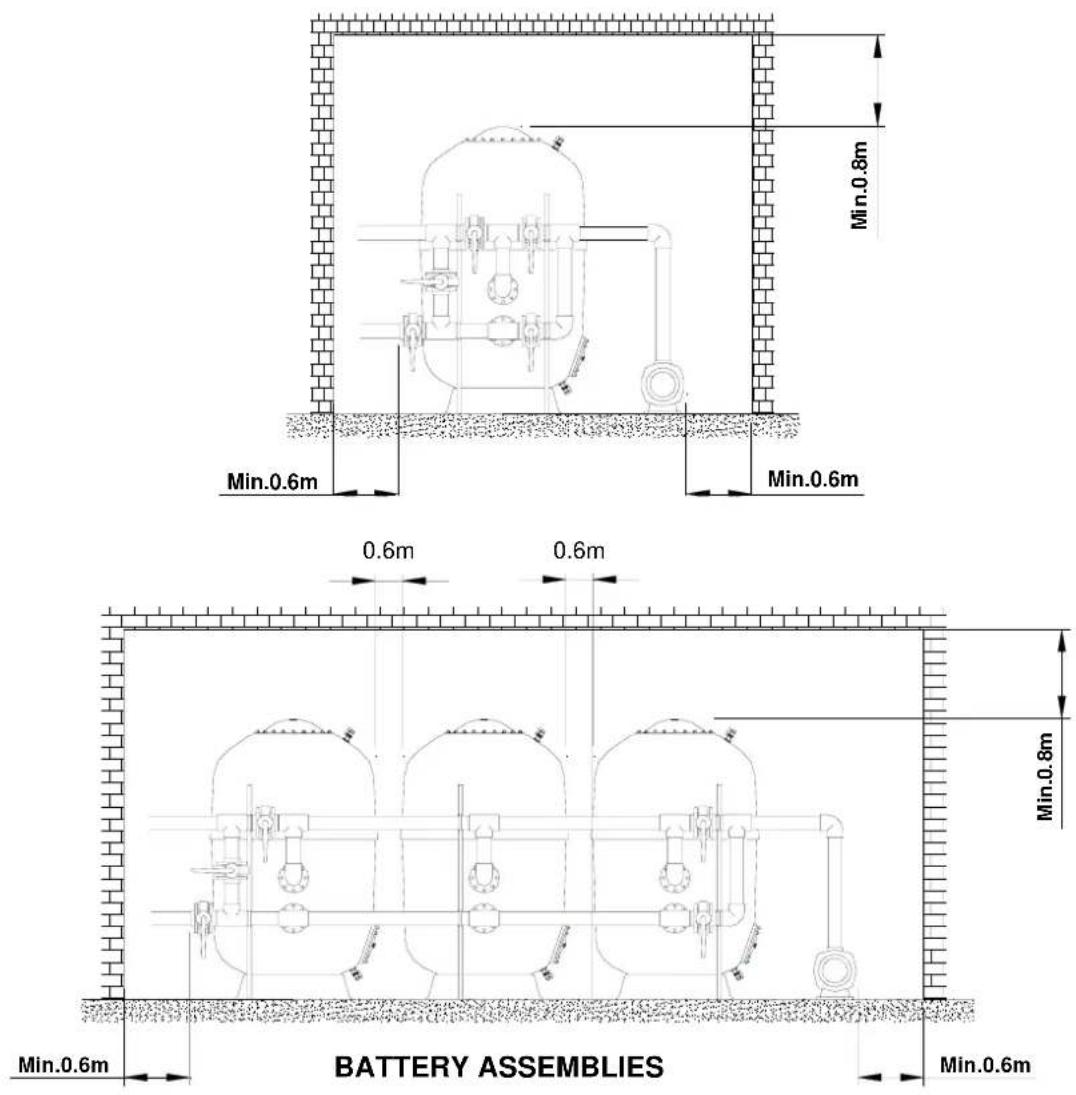
| Installation | On horizontal ground, free space around (0.6 m min.), adjustable supports |
| Spare parts | Seals, valves, pressure gauges, supports, diffuser, collector |
| Winter storage | Drain the filter, close the valves, open the cover for ventilation |
Frequently Asked Questions - Oslo ASTRALPOOL
User questions about Oslo ASTRALPOOL
0 question about this device. Answer the ones you know or ask your own.
Ask a new question about this device
Download the instructions for your Water filter in PDF format for free! Find your manual Oslo - ASTRALPOOL and take your electronic device back in hand. On this page are published all the documents necessary for the use of your device. Oslo by ASTRALPOOL.
USER MANUAL Oslo ASTRALPOOL
natural_image
3D rendering of a large industrial pressure vessel with internal pipes and valves (no text or symbols visible)INDUSTRIAL POLYESTER FILTERS FILTERS INTUSTRIELS EN POLYESTER FILTROS EN POLIÉSTER INDUSTRIALES INDUSTRIEFILTER IN POLYESTER-AUSFÜHRUNG FILTRI IN POLIESTERE INDUSTRIALE FILTROS EM POLIÉSTER INDUSTRIAIS
ASTRALPOOL

CHECK THE PACKAGING 1
1. GENERALITIES----1
1.1 Pool filters 1
1.2 Filters----2
1.3 Choosing the filters and the type of installation 2
1.3.1 Characteristics of the filters----2
1.3.2 Characteristics of the installation----2
2. INSTALLATION 3
2.1 Filter handling 3
2.2 Filter installation 4
a. Install the filter(s) into its (their) exact location----4
b. Assemble the battery(s) or selector valve and the pressure gauges correctly onto the filter(s)---5
c. Install the adequate supports and adjust them (height)----6
d. Connect the battery or selector valve with the pump return tubing, the return tubing to the pool and the drainage tubing----6
3. START-UP 7
5.1 4-valve batteries 9
5.2 5-valve batteries 9
6. TABLE OF HEAD LOSS FROM THE FILTERS, WITH SAND----9
7. MAINTAINING THE POOL FILTERS----10
7.1 Draining the sand from the filter 10
7.2 Wintering the filter 10
8. SAFETY WARNINGS----10
9. POSSIBLE FAULTS 11
CHECK THE PACKAGING
Check that the filter and all its components are in good condition after transportation. There is a box with the filter, which contains pressure gauges, along with other accessories. There will also be a guarantee.
1. GENERALITIES
1.1 Pool filters
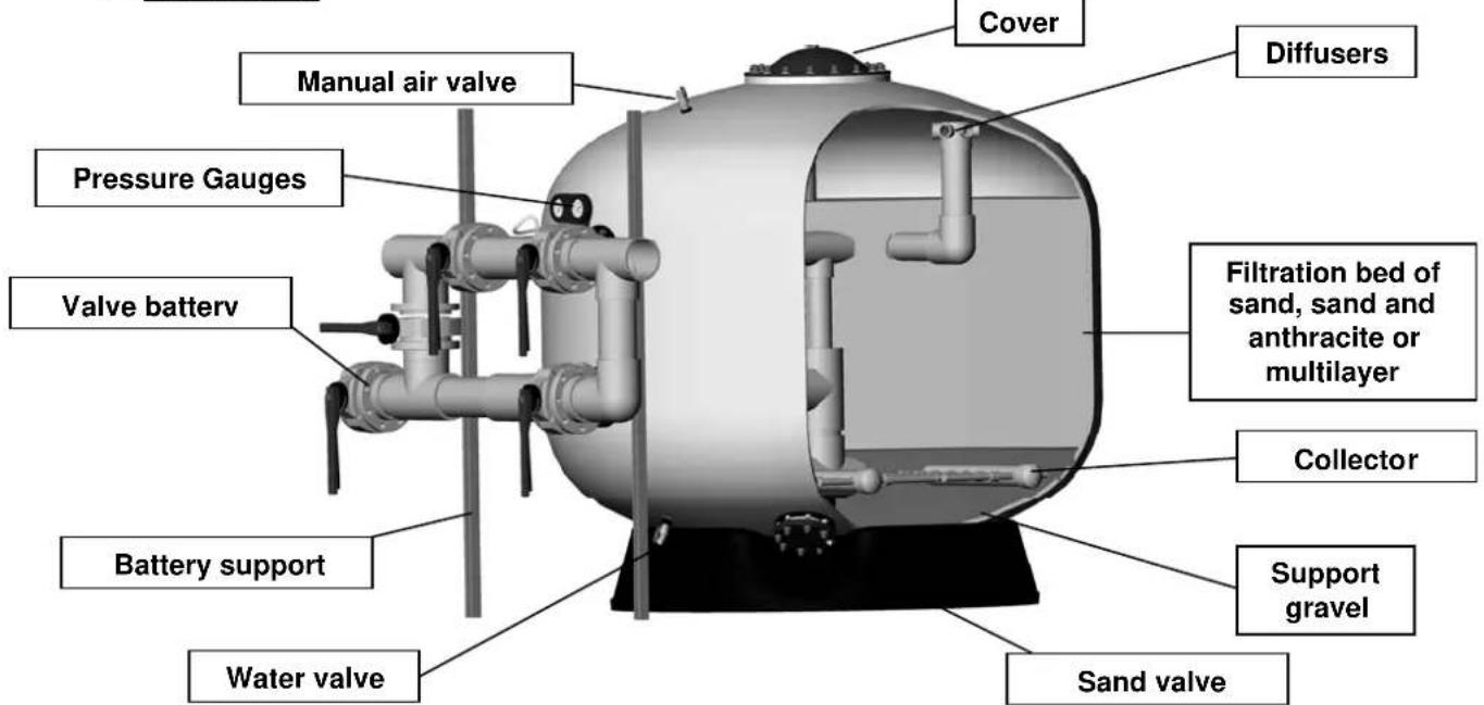
The filters are, without a doubt, the most important accessories for water clarification. And their object is to eliminate suspended materials that pollute the water.
The effectiveness of proper filtration affects the results of the water disinfectant.
The physical principle of filtration consists in trapping the suspended particles found in the water as they pass through the filtration sand bed.
The water filtration and purification process includes a whole variety of elements, besides the filter, to take into account, like the pumps, chemical water treatments, pool structure accessories for ensuring the return and suction of the water, as well as other elements capable of ensuring proper circulation and maintaining water quality.
Normally, each country has its own legislation, and the installers should consult them before carrying out any design or installment. For this reason, the elements and materials of the project should be designed and defined respecting the established standards.
Filtration quality depends on various parameters: the conception and form of the filter, the height of the filtration bed, the characteristics and grading of the filtration mass, etc. It should be noted that the filtration speed is a determining factor for obtaining good filtration quality.
Other important concepts to keep in mind when choosing a filter are the characteristics of the materials used in its manufacture, its working temperature and its working pressure.
1.2 Filters
For manufacturing the filter deposit, materials like polyester resins and fiberglass are used. The collector and diffuser, found inside it, are made of plastic material.
It designed to withstand admissible pressure and temperature showed in filter label. This pressure and temperature must never exceed as they mean maximum value. Regular working level always should be up to 20% below the maximum admissible pressure.
EXCLUSIVE FOR SWIMMING POOL
1.3 Choosing the filters and the type of installation
1.3.1 Characteristics of the filters
For properly filtering pool water, we recommend that the maximum re-circulation time for the entire water volume of the pool be the following:
Public pools 4 hours
Residential pools 8 hours
Public pools for children 1,5 hours
On the other hand, another important parameter that directly affects filtration quality is the speed of the water passing through the filters. We recommend the following speeds:
Public pools: 20 m³/h/m²
Residential pools: 40 m³/h/m²
For other applications, filtration velocity will depend on the effluent water velocity, application and the own installation design. Anyway, territorial legislation should be checked.
For proper filtration, we do not recommend exceeding 40 m^3/h/m^2 , keeping in mind that the filtration quality depends directly upon the grading of the filtration media and the height of the filtration bed.
Filters are designed to work under pressure. If there is some possibility depression happens, it is essential to install a double effect vacuum valve.
It is necessary to ensure that the installation conforms to the filters to prevent overpressure and depression.
1.3.2 Characteristics of the installation
For choosing the pump, you must take the necessary flow of 10 m.c.a. into account.
It is necessary to have installed an appropriate prefilter for the installation.
As for the number of pumps to be installed, we advise placing the same number of pumps as there are filters, each one with the flow necessary to obtain the desired filtration speed in a filter.
However, the return of each pump should flow into the general inlet tubing that is directed towards the filters. In this way, when the filters are filtering the pool water, all the pumps are operating. On the other hand, when you want to wash the filters, they are done alternately, meaning that with all the pumps operating, a determined number of filters will be closed (in order to obtain a wash speed from 40 to 50 m³/h/m²). Once the first group of filters is washed, these will close and then the second group will be washed.
With this set-up, we eliminate the need for having spare pumps for washing the filters.
Just like with the return, we recommend that the suction tubing of each pump comes from the general water suction tubing of the pool.
For obtaining good pool water quality, it is necessary to design the installation in such a way that the water to be filtered comes from both the surface and the bottom of the pool.
When calculating the return and suction tubing for the pool water, keep the following speeds in mind:
- Return line of filtered water to the pool: Maximum speed in the line: 2 m/sec
- Suction line of water to be filtered: Maximum speed in the line: 1.5 m/sec
It is important to design the installation to maintain a minimum stability (avoid excessive starting up and stopping up pumps) in order to avoid unnecessary continuous pressure variations in the filter as it can cause fatigue and reduces its life.
In addition, to reduce this effect, it is recommended to use of an inverter in the pump starts and stops in the pump in order to make the pressure increase or decrease as more linear as possible.
2. INSTALLATION
2.1 Filter handling
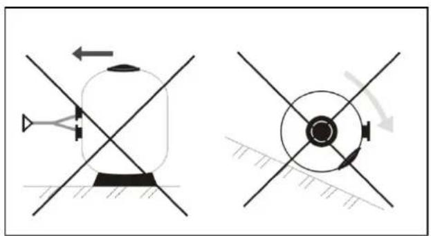
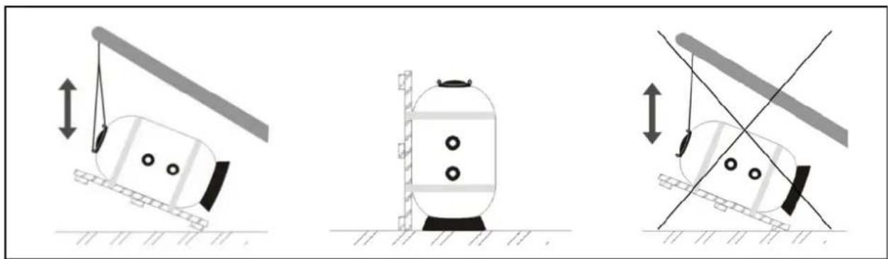
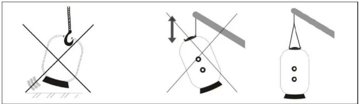
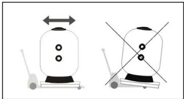
NOTE: Filters are delivered conveniently packed and due to their weight, size and difficulties arising in placing them, we recommend that their handling and movement be done with mechanical apparatus (forklifts, cranes, etc.).
natural_image
Two technical diagrams showing mechanical or fluid system configurations with directional arrows and crosshairs (no text or symbols)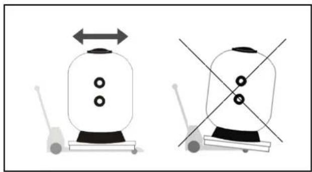
natural_image
Two identical illustrations of a robotic device with bidirectional arrow and crosshair, no text or symbols present.Never drag the filter Use an appropriate folklift filter remove the filter
natural_image
Three diagrams showing different mechanical setups with lifting weights and directional arrows (no text or symbols)Use both elevation rings to place the filter delivered in an horizontal position to vertical position
natural_image
Three diagrams showing different mechanical or structural configurations with no visible text or symbolsHooks are FORBIDDEN for moving filters
Use both elevation rings to move the filters
Sand should be loaded once the filter is installed into its exact location, following the instructions in the START-UP SECTION.
2.2 Filter installation
The steps to be taken for correctly installing the filters are the following:
a. Install the filter(s) into its (their) exact location
We recommend that the housing, where the filters are installed, has ventilation and adequate drains so that, in case of an accident, the water can escape through any tube, filter, pump, etc. By being able to evacuate it, the risk of damaging existing installations (pumps, control panels, etc.) is avoided.
If for any reason, these drains are unavailable, an alternative automated system should be installed for evacuating water from the chamber.
The filters should be installed in such a way that the base lies completely stable upon a totally horizontal surface.

natural_image
Two technical line drawings of a cylindrical device with internal components and mounting holes, one marked with a diagonal cross (no text or symbols)Set the filter on a totally horizontal surface
Given the fact that the filters require periodic inspections and in preparation for eventual interventions inside it, leaving a minimal amount of free space around and above the filter is ESSENTIAL
Once the installation is finished and before putting the sand inside the filter, you should start the system and check there is no leaking and all of the elements operate correctly.
b. Assemble the battery(s) or selector valve and the pressure gauges correctly onto the filter(s)
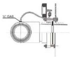
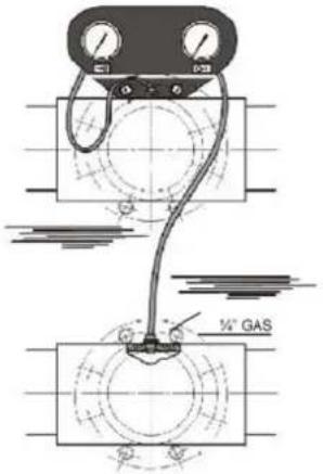
Once you have installed the pressure gauge panel on the flange of the filter connection, note the flexible plastic and transparent pipes that must be connected between the pressure gauges and the 14 " threaded holes in the battery tees, as the illustration shows. The pressure gauge panel clearly identifies the pressure gauge that controls the inlet and outlet pressures.
c. Install the adequate supports and adjust them (height)
Battery supports
Once the battery has been installed, should be installed special supports for supporting the weight of the battery and the water that circulates through it.
We recommend installing the following height-adjustable supports:
| ZINC-COATED STEEL TUBE (BARS) |
| Height of 1.85 m |
| Height of 2.30 m |
| Height of 3.00 m |
| ACCESSORY BOX |
| 2 anti-vibration brackets, anchor plug and accessories |
| For tube D 75 For tube ∅160 - 4 valves |
| For tube D 90 For tube ∅200 - 4 valves |
| For tube D 110 For tube ∅225 - 4 valves |
| For tube D 125 For tube ∅160 - 5 valves |
| For tube D 140 For tube ∅200 - 5 valves |
| For tube ∅225 - 5 valves |

- When choosing the bar, check out the height of the chosen filter's connections.
- For the accessory box, check out the diameter of the batteries and the number of valves.
- For the battery of just one filter, two bars and two accessory boxes are necessary, for batteries of two or more filters; we recommend at least one bar and box per filter.
For installing, first, you have to adjust the height of the brackets in relation to the battery and then fasten the support on the floor with the corresponding anchor.
Tubing supports
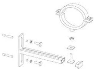
When assembling the installation, you have to place supports on the tubing sections in order to avoid vibrations and buckling that could damage or break them. For this reason, we recommend installing the supports:
| ∅ Tubing |
| 75 |
| 90 |
| 110 |
| 125 |
| 140 |
| 160 |
| 200 |
| 225 |
natural_image
Technical line drawing of a mechanical bracket assembly with mounting flanges and mounting hardware (no text or symbols)For installing them, follow the steps below:
• Take the bracket apart in two halves.
- Set the inner half of the bracket into the iron supports.
• Mark the position of the support.
- Drill the holes into the wall.
- Fasten the support onto the wall.
- Fasten the tubing with the flange
d. Connect the battery or selector valve with the pump return tubing, the return tubing to the pool and the drainage tubing
3. START-UP
ATTENTION: Do not clean the plastic components with products can damage the material
For correctly filling the filters with sand, it is essential:
Checking
- After finishing the installment and before placing media inside the filters, you should carry out a hydraulic check of both the filters and the installation in order to make sure that it is assembled properly. Drain the filter.
- Removing the filter cover, trying not to damaging the joint and the cover lock.
- Making sure all the filter components (collector arms, etc.) are in good shape, since they could have suffered some damage during transport.
Starting-up
- Filling the filter about halfway with water. Fill the filter media carefully starting from the bottom layers (taking into account its granulometry respect to slot pitch of the collecting system) until covering the collector system (approximately 10 cm). This should be done very carefully so as not to damage the inner filter components. As the filter is being filled with sand, take the precaution of distributing the sand over the entire filter surface.
- To help on the homogeneous distribution of the sand it is necessary to perform a short filter washing In the middle of the charging process.
- Introducing filter media in size up to the maximum limit of filtration height (refer to model)
- Clean the surface of the filter neck, the joint and the cover meticulously before assembling. Closing the filter by placing the joint in the correct position and replacing the cover carefully without moving it from its position
Before starting, after loading and conveniently closing the filter, washing the filter is necessary. In order to do so, follow the instructions in the filter wash section.
NOTE: The manufacturer is not responsible for any damage caused to the filter on handling, installation and starting up operations
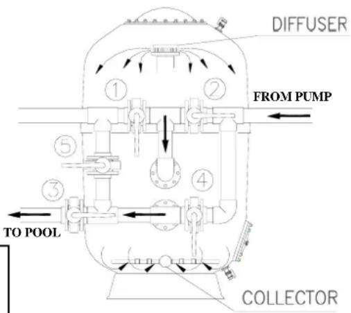
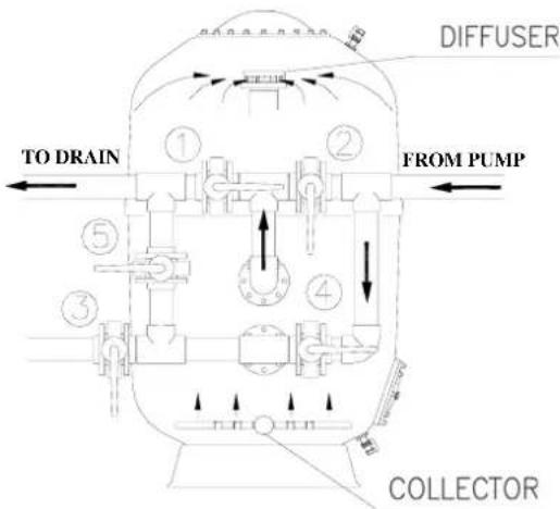
WITH THE PUMP STOPPED, place the valves in the filter position indicated in the diagram.
As the filtration bed gets dirty through use, the inlet pressure gauge will experience an increase in pressure while the outlet pressure gauge will suffer a drop. So, we recommend periodically observing the pressure gauges of the inlets and outlets and washing the filter when the pressure difference is equal to or greater than the label shows.
As for filters with nozzle plate, it is highly recommended to wash (section 4.2) when the pressure difference is 0.6 bar. This difference can never exceed 0.8 bar
ATTENTION: NEVER EXCEED FILTER'S MAXIMUM ADMISSIBLE PRESSURE
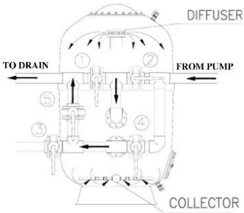
4.2 Wash
For performing the wash operation and ALWAYS WITH THE PUMP STOPPED, place the valves in the wash position indicated in the diagram.
Filtration bed forms thousands of water canals, which logically collect the impurities and solid residues that comes from filtering water. With time, these residues block the water canals, so that periodically cleaning the filter in order to leave it in optimal working conditions and pouring the dirt found in the filtration bed through the drain is necessary.
It is recommended washing time would be 7 minutes at a speed between 40 and 50 m ^3 /h/m ^2 .
We advise placing a sighting-tube in the drainage tubing in order to observe the dirtiness of the water coming from the filter when cleaning and to determine the length of the washing time.
Not surpassing 50 m^3/h/m^2 in order to avoid some of the sand from being expelled through the drain and to prevent damage to the filter. Check filtration media characteristics.
When using air to perform a backwash, use the adequate air flow (recommended rates of 60 m^3/h/m^2 ). NEVER USE A COMPRESSOR, since this could severely damage the filter. Use a blower, ensuring that the internal pressure of the filter when backwashing does not exceed 1 bar. Make sure that there is an air vent open when backwashing with air.
4.3 Rinse
This operation is recommended after the WASH. Its objective is expelling the remains of residues that could have penetrated the collectors during the wash cycle of the filter.
This operation should be done during 3 minutes and this will prevent water contamination.
For performing this operation, place the valves into the rinse position indicated in the diagram, ALWAYS WITH THE PUMP STOPPED, and immediately after, place them to the filter position.
The rinse operation can only be performed if the battery has 5 valves or if we have a selector valve in the filter.
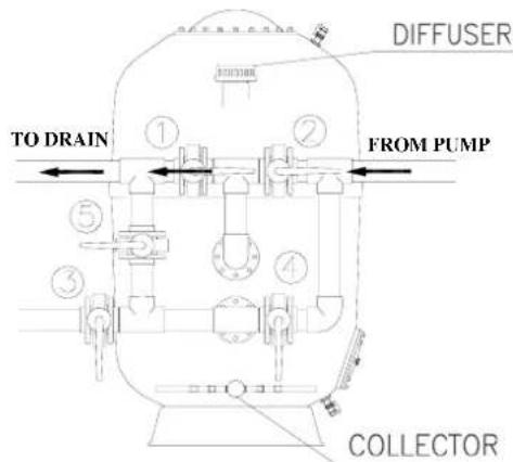
4.4 Drainage
Empty the pool when necessary and in case the pool does not have a drain on the bottom directly connected to the sewer system, drainage can be carried out by using the filter pump. Place the valves in drainage position indicated in the diagram.
For this end and before connecting the drainage, the skimmer valves, the overflow canal and the bottom cleaner must be closed
4.5 Closure
As its name indicates, all the battery valves are closed.
This operation is used for maintaining the filter, cleaning the pre-filter, etc.
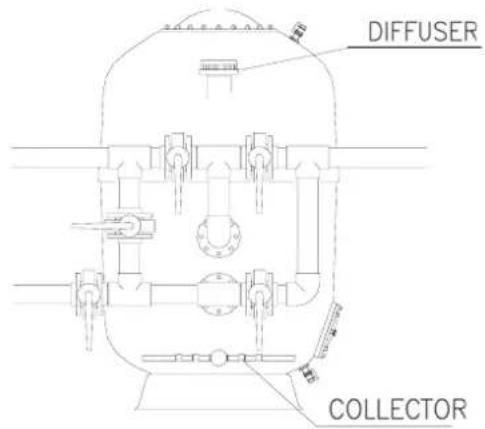
5. VALVE BATTERY. THEIR POSITION IN EACH OPERATION
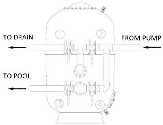
5.1 4-valve batteries
Control diagram for 4-valve batteries.
| Position | 1 | 2 | 3 | 4 |
| Filtration | Closed | Open | Open | Closed |
| Wash | Open | Closed | Closed | Open |
| Drainage | Open | Open | Closed | Closed |
| Closure | Closed | Closed | Closed | Closed |
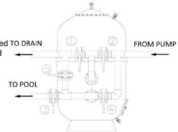
5.25-valve batteries
Control diagram for 5-valve batteries.
| Position | 1 | 2 | 3 | 4 | 5 |
| Filtration | Closed | Open | Open | Closed | Close |
| Wash | Open | Closed | Closed | Open | Close |
| Rinse | Closed | Open | Closed | Closed | Open |
| Drainage | Open | Open | Closed | Closed | Closed |
| Closure | Closed | Closed | Closed | Closed | Closed |
6. TABLE OF HEAD LOSS FROM THE FILTERS, WITH SAND
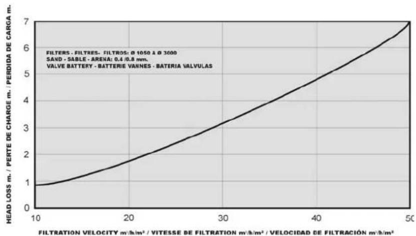
line
| FILTRATION VELOCITY m/h/m² / VITESSE DE FILTRATION m/h/m² / VELOCIDAD DE FILTRACIÓN m/h/m² | HEAD LOSS m. / PERTE DE CHARGE m. / PERDIDA DE CARCA m. | | --- | --- | | 10 | 1.0 | | 20 | 1.8 | | 30 | 3.2 | | 40 | 4.8 | | 50 | 7.0 |7. MAINTAINING THE POOL FILTERS
- Always having the filters in the proper conditions is important, since the good quality of the water depends on it.
- Having all the components in the proper conditions is important. For this end, they should be checked regularly, and deteriorated joints and pieces should be substituted when necessary.
- For cleaning the filter, do not use solvents, since they can damage components made with plastic material. The filter can be cleaned easily with water and soap.
- Media should be changed periodically. Check to your supplier.
- The filtrate media and the inlet/outlet connections, it should be adequate and it should be maintained in good conditions to avoid the polyester degradation.
7.1 Draining the sand from the filter
Pay attention to security warnings
For emptying sand from the filter, proceed in the following way:
- Drain the water from the filter.
- Remove the cover.
- As the sand is draining, remove it from the valve in order to prevent blockage.
- It will be necessary for someone to enter the filter through the upper mouth in order to bring the sand closer to the valve for facilitating its exit.
For refilling the filter with sand, follow the START-UP instructions.
7.2 Wintering the filter
For not damaging the filter components during the wintertime, the following steps are necessary:
- Carry out a wash and rinse according to the instructions.
- Stop the pumps.
- Drain the water from the filter.
- Close the valve of the suction and return tubing in order to isolate the filter.
- Remove the cover from the filter in order to keep the filter ventilated during the period of inactivity.
- We advise draining all the tubing in order to prevent them from bursting in case of frosts.
8. SAFETY WARNINGS
- Before manipulating the filter or valves, make sure that the pump is stopped and the filter has no pressure. For greater safety, disconnect the pump and possible electric installations connected to the mains
- Never connect the filter directly to the water supply, since its pressure can be higher than the maximum pressure of the filter
- Always evacuate the air from inside the filter before starting a cycle
- Due to the unions are made with joints, fastening the nuts very tightly is not necessary
- Do not clean plastic pieces with solvents, they could lose their properties
- Do not let children manipulate the filter or play near them
- Protect the filter from freezing
- Before connecting the pump, make sure that the filter cover is properly closed
-
Install the filter in an area provided with ventilation and adequate drains as close as possible to the pool tank, below the water level of the pool in order to avoid causing a depression inside it
-
POSSIBLE FAULTS
| PROBLEM | CAUSE | SOLUTION |
| Little filtration flow | Pump pre-filter is dirty Clean the | pre-filter |
| The pump motor rotates backward | Reverse the rotation direction of the pump motor | |
| Dirty filter Perform a «wash» | ||
| Tubing blocked Clear tubing | ||
| The pump takes air Check the entire system and eliminate possible leaks | ||
| The pressure gauge oscillates violently | The pump takes air Check for leaks in the pre-filter and suction tubing | |
| Suction in semi-closed Make sure the suction valves are open | ||
| The pump takes air | Algae in the pool Chemically treat | |
| Dirty filter Perform a «wash». | ||
| Water pH is high (cloudy water) Lower the pH | ||
| Lacking chlorine (greenish water) | Add chlorine | |
| Rapid rise in pressure: bubbles in the nozzles | Low level of pool water Fill the pool | |
| Suction valves are partially closed | Check and open the valves | |
| Pump pre-filter is dirty | Clean the pre-filter | |
| Pressure gauge oscillates violently | The pump has air in it | Check the whole installation and eliminate possible leaks |
| Suction half closed | Check the suction valves are completely open | |
| Sand is entering in the pool from the filter | There is something broken in the collector system | Repair the collector system |
| Sand is escaping to the drain during backwash | Excessive water flow during backwash | Reduce the flow rate during backwash |
| Leaks in the connections or lids | Loose screws, dirty joints or misplaced | Tighten the screws, being careful not to break any plastic pieces, clean or install the joint correctly. If the problem is not resolved, phone technical support |
- When in doubt, consult service
- In case of breach of manual, the manufacturer is not liable for any damage caused
VERIFICATION DE L'EMBALLAGE----1
1. GÉNÉRALITÉS----1
natural_image
Two technical diagrams showing mechanical or fluidic components with directional arrows, no text or symbols present.natural_image
Two identical illustrations of a device with bidirectional arrow and crosshair, no text or symbols presentnatural_image
Three diagrams showing different mechanical setups: a lever lifting a cylindrical object, a vertical cylinder with circular holes, and a horizontal platform with diagonal lines (no text or symbols)natural_image
Three diagrams showing different mechanical or structural configurations with no visible text or symbolsnatural_image
Technical line drawing of a mechanical bracket assembly with mounting holes and a circular component (no text or symbols)natural_image
Two schematic diagrams showing mechanical or fluid system configurations with intersecting lines and directional arrows (no text or symbols)natural_image
Two identical diagrams showing a device with bidirectional arrow and a cross symbol, no text or labels present.natural_image
Three diagrams showing a cylindrical tank under different load conditions: one with upward motion, one with vertical support, and one with horizontal force (no text or symbols)natural_image
Three diagrams showing different mechanical or structural configurations with no visible text or symbolsnatural_image
Technical line drawing of two identical mechanical components with circular features, one marked with a diagonal cross (no text or symbols)natural_image
Technical line drawing of a mechanical bracket assembly with mounting holes and mounting feet (no text or symbols)natural_image
Two technical diagrams showing mechanical or fluidic components with directional arrows, no text or symbols present.natural_image
Pure mechanical diagram showing a circular component with crosshairs and an arrow indicating rotation, no text or symbols present.natural_image
Two identical illustrations of a device with bidirectional arrow and crosshair, no text or symbols presentnatural_image
Three diagrams showing a mechanical setup with a lever, a tank, and an inclined plane (no text or symbols)natural_image
Three diagrams showing different mechanical or electrical configurations with no visible text or symbolsnatural_image
Technical line drawing of two identical mechanical components with circular features, one marked with a diagonal cross (no text or symbols)natural_image
Technical line drawing of a mechanical bracket assembly with mounting holes and mounting feet (no text or symbols)natural_image
Two schematic diagrams showing directional arrows and crosshairs, no text or symbols presentnatural_image
Diagram showing a circular object with intersecting lines and an arrow indicating rotation, no text or symbols present.natural_image
Two identical diagrams showing a device with bidirectional arrow and a cross symbol, no text or labels present.natural_image
Three diagrams showing different mechanical setups: a lever lifting a cylindrical component, a vertical cylinder with circular holes, and an inclined plane lifting a cylindrical component (no text or symbols present)natural_image
Three technical diagrams showing mechanical assembly or lifting process with no visible text or symbolsnatural_image
Technical line drawing of two identical mechanical components with mounting holes and a diagonal cross mark (no text or symbols)natural_image
Technical line drawing of a mechanical assembly with mounting brackets and a circular component (no text or symbols)ATTENZIONE: NON SUPERARE MAI LA PRESSIONE MASSIMA AMMISSIBILE DEL FILTRO
4.2 Lavage
4.5 Chiusura
natural_image
Two schematic diagrams showing mechanical or fluid system configurations with directional arrows, no text or symbols present.Nunca arraste o filtro
natural_image
Two identical illustrations of a device with bidirectional arrow and crosshair, no text or symbols presentnatural_image
Three diagrams showing a mechanical setup with a load-bearing cylinder, a vertical tank, and an inclined plane (no text or symbols)natural_image
Three diagrams showing different mechanical or structural configurations with no visible text or symbolsnatural_image
Technical line drawing of two identical mechanical components with circular features, one marked with a diagonal cross and the other with a horizontal line (no text or symbols)natural_image
Technical line drawing of a mechanical assembly with mounting brackets and a circular component (no text or symbols)
- CHECK THE PACKAGING 1
- GENERALITIES----1
- INSTALLATION 3
- START-UP 7
- TABLE OF HEAD LOSS FROM THE FILTERS, WITH SAND----9
- MAINTAINING THE POOL FILTERS----10
- SAFETY WARNINGS----10
- POSSIBLE FAULTS 11
- CHECK THE PACKAGING
- GENERALITIES
- Filters
- EXCLUSIVE FOR SWIMMING POOL
- Choosing the filters and the type of installation
- Characteristics of the filters
- Characteristics of the installation
- INSTALLATION
- Filter handling
- Filter installation
- a. Install the filter(s) into its (their) exact location
- b. Assemble the battery(s) or selector valve and the pressure gauges correctly onto the filter(s)
- c. Install the adequate supports and adjust them (height)
- Battery supports
- Tubing supports
- START-UP
- Checking
- Starting-up
- Wash
- Rinse
- Drainage
- Closure
- VALVE BATTERY. THEIR POSITION IN EACH OPERATION
- 4-valve batteries
- 5.25-valve batteries
- TABLE OF HEAD LOSS FROM THE FILTERS, WITH SAND
- MAINTAINING THE POOL FILTERS
- Draining the sand from the filter
- Wintering the filter
- SAFETY WARNINGS
- VERIFICATION DE L'EMBALLAGE----1
- GÉNÉRALITÉS----1
- Lavage
- Chiusura
Brand : ASTRALPOOL
Model : Oslo
Category : Water filter