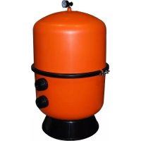
Bilbao - Water filter ASTRALPOOL - Free user manual and instructions
Find the device manual for free Bilbao ASTRALPOOL in PDF.


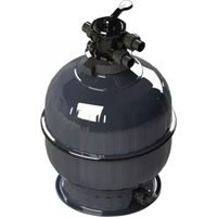
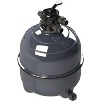
| Product type | Sand filter for swimming pool |
| Brand | AstralPool |
| Model | Bilbao |
| Multi-position valve positions | Filtration, Wash, Rinse, Recirculation, Drain, Closed |
| Tank material | Reinforced plastic |
| Filter media | Silica sand (grain size 0.5-0.7 mm) |
| Maximum working pressure | 2.5 kg/cm² (approx. 35 PSI) |
| Wash indication | Pressure increase of 0.5 kg/cm² compared to initial pressure |
| Operating temperature | 0 °C to 50 °C |
| Connection | Plastic pipes (1 ½" or 2") with Teflon joints |
| Installation | Horizontal, clean surface, preferably 0.50 m below water level |
| Maintenance | Backwashing when pressure increases; pre-filter cleaning; sand replacement every 3 years |
| Winterizing | Drain water, remove cover, ventilate |
| Safety | Do not operate without water; stop the pump before changing valve position; do not use solvents |
| Warranty | 2 years standard; extension possible up to 5 or 10 years (depending on model) |
| Dimensions (L x W x H) | Not specified in the manual |
| Weight | Not specified |
Frequently Asked Questions - Bilbao ASTRALPOOL
User questions about Bilbao ASTRALPOOL
0 question about this device. Answer the ones you know or ask your own.
Ask a new question about this device
Download the instructions for your Water filter in PDF format for free! Find your manual Bilbao - ASTRALPOOL and take your electronic device back in hand. On this page are published all the documents necessary for the use of your device. Bilbao by ASTRALPOOL.
USER MANUAL Bilbao ASTRALPOOL
natural_image
Two white industrial pressure vessel containers with black and white components, no visible text or symbols.INSTALLATION AND MAINTENANCE MANUAL MANUEL D'INSTALLATION ET D'ENTRETIEN MANUAL DE INSTALACIÓN Y MANTENIMIENTO MANUALE DI INSTALAZIONE E MANUTENZIONE EINBAU-UND BETRIEBSANLEITUNG MANUAL DE INSTRUÇÕES E MANUNTENÇÃO

BILBAO
IMPORTANT: The instruction manual you are holding includes essential information on the safety measures to be implemented for installation and start-up. Therefore, the installer as well as the user must read the instructions before beginning installation and start-up. Keep this manual for future reference.
To achieve optimum performance of the Filter, follow the instructions provided below:
What happens to the water in your pool?
This should be a question of prime consideration for all pool owners. In the past some pools did not use filtering systems, the owner was faced with the problem of refilling the pool with clean water when this became necessary. Refilling the pool was laborious, meanwhile the owner had an unsanitary pool with unpleasant bathing owing to the poor clarity of the water. Today pool owners demand absolute hygiene, crystal clear water and economy of effort. These objectives are achieved by effective filtration and chemical treatment of the pool water.
After filling the pool with clean water in the summer, two basic factors can take place due to the exposure of water to the sun and the air.
1.-Biological contamination. The water is contaminated by micro-organisms which may be airborne or introduced by bathers. These parasites reproduce rapidly in still warm water and algae may form giving a greenish appearance to the pool water.
2.-Rainfall and wind may introduce dust, with leaves and seeds which muddy and pollute the pool water. These two factors generate in little time an unsanitary swimmingpool and unpleasant bathing.
Solutions to the problem:
1.-"CHEMICAL" TREATMENT
Maintain the correct level of sanitiser (chlorine, brom, oxygen...) in the water to combat existing micro-organisms by its disinfecting action.
As chlorine is the more common method, it will be taken as the reference point.
2.-"PHYSICAL" TREATMENT
Provide the pool with a filtration system (filter and pump) to remove suspended particles from the water.
PH LEVEL
The pH level is an indicator of acidity or alkalinity present in the water. The neutral value is 7.0. a pH of 0-7 means levels of acidity whilst 7-14 gives levels of alkalinity. The pool usual readings vary between 6.8 and 8.4.
Why pH is important?
"THE IDEAL PH VALUE IN A POOL SHOULD BE BETWEEN 7.2 AND 7.6".
As previously stated, sufficient residual chlorine must exist in the pool to destroy unwanted micro-organisms, in fact the chlorine will only act as a bactericide when the pool water has a pH of between 7.2 and 7.6.
There are other reasons which call for a correct pH level: Once above 7.6, calcium in the pool will precipitate to a visible cloudy form (accentuated in hard water areas).
This gives a milky appearance to the water, and hinders the filtering, deposits may also appear on the pool walls and fittings.
Once the pH level falls below 7.0 the pool water becomes corrosive causing eye irritation and affecting mucous membranes. There is also a long term threat to metallic parts in the pool.
The quality of the pool water is highly dependent on maintaining the correct pH level.
CHLORINE
Standards for the amount of residual (free) chlorine in the pool water may vary from country to country, depending on health authority regulations. Typical legal requirements are between 0.2 and 0.6 parts per million, (i.e. 0.2-0.6 milligrams per litre).
What is understood by free or residual chlorine?
Even after the filtering process, certain bacteria remains to be destroyed by the disinfecting action of the chlorine which is usually acting on the bacteria in the form of hyperchloric acid.
A quantity of chlorine that is added to the water (in excess of that needed to destroy bacteria and oxidize organic material) remains free to combat new bacteria introduced by bathers or atmospheric agents.
This chlorine remaining in the water in the form of hyperchloric acid is known as free, residual chlorine.
FILTRATION
It is essential that the filtration is accompanied by chemical treatment of the pool water. The two processes are complimentary to each other.
WORKING PRINCIPLES
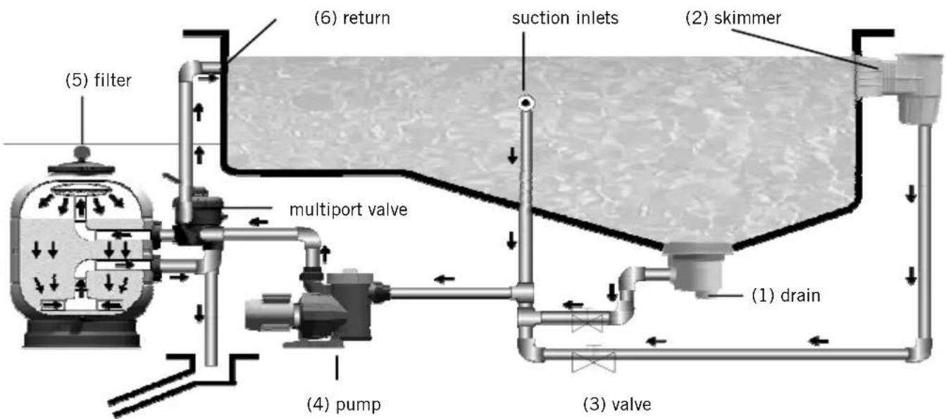
A suction is taken from the main drains (1) on the bottom of the pool and the skimmers (2) at the pool surface and fed via separate pipework with their corresponding valves (3), through the pump (4) to the sand filter (5).
After filtration, the water is returned to the pool via return inlets (6), which are installed on the opposite side of the pool to the skimmers and main drains.
Once in the filter, the water is circulated downwards through silica sand and suspended particles are retained. The filter sand needs to be washed at intervals to remove the particles it has retained backwash.
This is achieved by reversing the flow through the filter and directing the water containing the dislodged particles to drain. When the filter pressure increased by 0.5 kg/cm^2 or more with respect to the initial pressure means that the sandfilter needs to be backwashed.
Bearing these principles in mind, the following installation and operation instructions should not represent any problem.
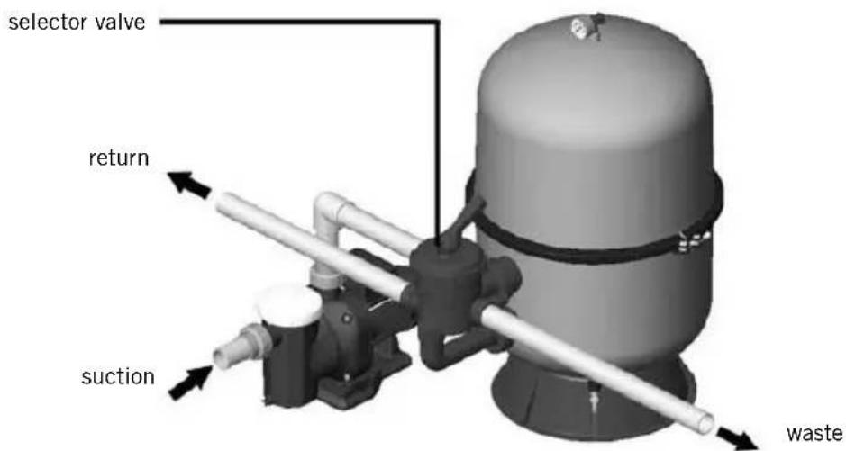
The filter should be installed as close as possible to the swimming pool and preferably at a level of 0,50 metres below the surface of the water in the swimming pool. Make sure there is drainage available at the place where the filter is to be installed.
ATTENTION
If the filter is installed indoors, a correctly sized drain should be installed, to drain off as much water as possible from the swimming pool, to avoid flooding risks of the premises or adjoining areas. If this is not done, the filter manufacturer will not be held liable for possible damage to third parties caused by the filter.
IMPORTANT: Do not use an iron and hemp pipe for the selector valve connection, it is essential to use plastic accessories and TEFLON tape. Pipe terminals are available threaded fixing in 1 ½ “and 2”.
Always leave enough space round the filter in order to perform the necessary examinations and maintenance during the filter's life.
ASSEMBLY
Follow these indications for a correct assembly of the filter:
1.- Place the filter on a horizontal and clean surface.
2.- Place the filter in its final location.
3.- In case of a filter with a lateral valve, install the selector valve in the filter. Make sure that the joints between the valve and the filter are correctly placed.
4.- Perform the three connections of the selector valve: pump piping to the valve, valve to the waste drain and valve to the pool return. Each of these three outlets is clearly identified on the valve.
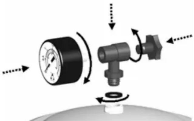
5.- Set the manometer T, the joint, the manometer and the air drainage (see exploded view). It is not necessary to use teflon tape, as the watertightness is guaranteed in this case by the joint. Do not tighten the manometer T with a tool, as manually will be sufficient.
natural_image
Diagram of a pressure regulator with rotating valve and adjustment knob (no text or labels)ASSEMBLY OF THE MANOMETER (WITH VALVE)
SAND LOAD
In order to obtain maximum efficiency from your filter, it should be filled with silica sand with a grain size classification of 16 / 32 inches. With the quantity indicated on the plate specifying the characteristics; proceed as follows:
Load up when the filter is installed in position and the connection pipes have been joined.
1.- Unscrew the lock screws and remove the collar.
2.- Take off the lid and joint, take care that the lock protection Ring does not fall.
3.- Fill the filter with water to half capacity.
4.- Pour the required, slowly and very carefully, quantity of sand inside the filter.
5.- Clean the seating of the lid joint.
6.- Fix the filter lid in place.
7.- Place the collar back and tighten the screws.
Attention: when operating check that water does not leak from the filter through the collar.
Note: the manufacturer will not be held responsible for any damage caused to the filter while filling it with sand.
The selector valve has a handle of 6 positions that selects any of the necessary operations to obtain the maximum efficiency from the filter.
IMPORTANT: Always switch off the pump, when changing the position of the selector valve.
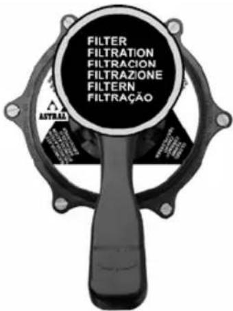
FILTRATION
With the pump switched off, place the handle of the selector valve in the FILTERING position.
Switch on the pump.
When starting up for the first time, read the pressure of the pressure gauge. It is recommended to take note of this pressure, as later it will be used to know whether the filter is dirty and if “WASHING” is required. “WASHING” should be done when the pressure gauge indicates an increase of 0.5 kg/cm^2 with respect to the initial pressure of the filter. It is advisable to observe the pressure gauge from time to time as this indicates the degree of saturation of the filter
Bear in mind that the valves at the bottom of the pool and the skimmers will be adjusted according to the amount of floating particles on the surface of the water. The main drain and skimmer valves will be regulated according to the quantity of floating material found on the surface of the water. Bear in mind that with the main drain valve fully open there will be little suction from the skimmers. If the surface sweep of the skimmers is to be stronger, reduce the flow from the main drain.
0,8 kg/cm ^2 - 11,4 PSI: Initial pressure of the filter at the start of a filtering cycle.
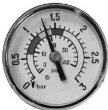
1,3 kg/cm ^2 - 18,5 PSI: The pressure is 0.5 kg/cm ^2 more than the initial pressure, indicating that WASHING is required.
BACKWASH
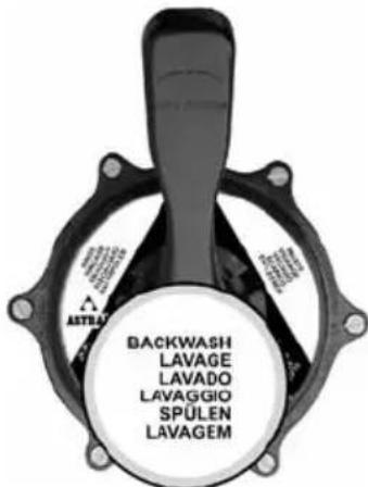
Each load of sand forms thousands of channels which pick up all the material contained and caught up in the filtering process, the number of free channels allowing the water to pass is continually decreasing. This is why the pressure rises progressively until it an increase of 0.5 kg/cm^2 . At this pressure the filtering sand is unable to collect any more impurities and must be cleaned as follows:
Turn the selector valve to the "BACKWASH" position and with the main drain and return valves open, switch on the pump and run it for 2 minutes. When this operation is completed, the dirt blocking the filter will have been removed.
In this position, the selector valve allows the water from the pump to go directly to the swimming pool without passing through the inside of the filter.
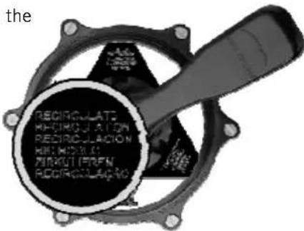
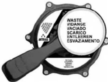
WASTE
If the swimming pool needs to be drained, this can be done using the filter pump. In order to do this, the selector valve should be in the "WASTE" position. The motor is run with the main drain valve fully open, for the pump to have sufficient suction. For the pump to suction, keep the prefilter and the main drain pipes full of water. Before drainage, make sure that the skimmer valves and the bottom cleaner valves are closed.
RINSE
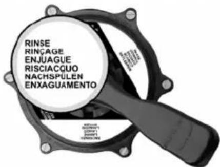
After the carrying out the “BACKWASH” operation on the filter and placing the installation in the “FILTER” position, the water flowing into the swimming pool will be cloudy for a few seconds, so to prevent it from reaching the swimming pool there is a “RINSE” position for the selector valve which is operated as follows: immediately after the “BACKWASH” put the valve in the “RINSE” position and switch on the pump for 1 minute, after which the pump is switched off and the valve placed in the “FILTER” position.
This position ensures that the filtered water goes directly to the drain.
CLOSED
As its name indicates, this position is for closing off the water from the of the filter pump and it is used for opening the collector prefiltre of the pump.

START-UP
When the filter has been loaded, the sand must be washed. Proceed as follows:
1.-Open the air bleed cap to blow out the air.
2.- Place the selector valve in the "LAVADO" (BACKWASH) position.
3.- Open the valves controlling the swimming pool suction pipes and run the pump for 4 minutes.
4.- Stop the pump, place the handle of the selector valve into the "RINSE" position and rinse for 1 min. Then, stop the pump and place the handle of the selector valve into "FILTRATION" (FILTERING) position.
5.- Close the air bleed cap when water starts to come out.
When this has been done, the filter will be ready to start the filtering cycles for the water in the swimming pool.
IMPORTANT: The pump should be switched off when the position of the selector valve handle is being changed.
Do not use solvents for cleaning the filter, this could damage the filter, especially its finish.
Always replace the joints and pieces that may not be in good condition.
Backwash and rinse when needed, as per the instructions specified in this manual.
Clean the sand every year for a better performance with solid or liquid ASTRAL Filnet product. It's recommended to change the sand inside the filter approximately every 3 years.
Winter period, in order not to damage the filter during the winter period, please follow the instructions below:
Perform a backwash and a rinse as previously detailed.
Remove the water from the filter.
Take off the lid to ventilate the filter in the period of inactivity.
When you need to start up the filter again after a period of inactivity, follow the instructions stated in the paragraph "START UP".
The most common PROBLEMS
| EFFECT POSSIBLE CAUSE | SOLUTION | |
| The filter only provides a small volume of the filtered water.Vacuum heads have poor suction. | Prefilter blocked. Clean filter. | |
| Motor turning the wrong way. | Check by the arrow on the body of the prefilter which way the motor is turning, if this is not correct, reverse the motor connection. | |
| Suction pipes are blocked. Proceed to clean. | clean. | |
| The pressure gauge varies considerably. | The pump is taking in air. | Check for leaks in the prefilter and suction pipes. |
| Suction is half closed. | Check that the suction valves are completely open. |
SAFETY WARNINGS
Never start up the system without water.
Whenever you operate the filter or the selector valve, switch off the pump first.
Never allow children or adults to sit on the system.
Do not connect the filter directly to the water network, as the pressure of the water may be too high and exceed the maximum work pressure allowed by the filter.
Do not use the filtering circuit to fill and adjust the water level of the pool. A handling error may lead to overpressure in the filter.
Do not clean the lid with solvents, as it may damage its properties (finish, transparency ...).
As all the connections are made with joints, it is not necessary to tighten the nuts excessively in order to avoid that some plastic pieces could break.
DO NOT use teflon in the T-part of the pressure gauge Kit, code 00545R0300, to ensure sealing.
1. GENERAL TERMS
1.1. In accordance with these provisions, the seller guarantees that the product corresponding to this guarantee is in perfect condition at the time of delivery.
1.2. The Guarantee Term for the Product is two (2) years from the time it is delivered to the purchaser.
1.3. In the event of any defect in the Product that is notified by the purchaser to the seller during the Guarantee Term, the seller will be obliged to repair or replace the Product, at his own cost and wherever he deems suitable, unless this is impossible or unreasonable.
1.4. If it is not possible to repair or replace the Product, the purchaser may ask for a proportional reduction in the price or, if the defect is sufficiently significant, the termination of the sales contract.
1.5. The replaced or repaired parts under this guarantee, will not extend the guarantee period of the original Product, but will have a separate guarantee.
1.6. In order for this guarantee to come into effect, the purchaser must provide proof of the date of purchase and delivery of the Product.
1.7. If, after six months from the delivery of the Product to the purchaser, he notifies a defect in the Product, the purchaser must provide proof of the origin and existence of the alleged defect.
1.8. This Guarantee Certificate is issued without prejudice to the rights corresponding to consumers under national regulations.
2. INDIVIDUAL TERMS
2.1. This guarantee covers the following products and ranges: BILBAO model filters.
2.2. For this guarantee to be effective, the purchaser must strictly follow the Manufacturer's instructions included in the documentation provided with the Product, in cases where it is applicable according to the range and model of the Product.
2.3. When a time schedule is specified for the replacement, maintenance or cleaning of certain parts or components of the Product, the guarantee will only be valid if this time schedule has been followed.
2.4. The manufacturer of the product offers the possibility of extending the guarantee of Bilbao filters from the third year up to the fifth or tenth year depending on the model as indicated below. This Guarantee Extension is governed by the following terms:
2.4.1. Coverage of the Guarantee Extension by the Manufacturer: In the event of any defect or non-conformity in the container of the filter, the manufacturer will repair or replace the filter as he sees fit.
2.4.2. Replacement will construe that the purchaser accepts the payment of a variable charge depending on the age of the product, as indicated in the following tables:
| Time from the date of acquisition of BILBAO, model filters | Payable percentage of the price at the time of the claim |
| from 3 to 4 years 60% | |
| from 4 to 5 years 80% |
2.4.3. The manufacturer of the filter also offers the possibility of extending an additional guarantee during the third year for internal and external components of the filter.
2.4.4. The filtering means is excluded from any guarantee extension.
2.4.5. Other terms during the guarantee extension from the third year are:
- In the event of replacement, all transport charges or expenses to or from the factory, for moving or reinstalling the product or installing a spare part, will be covered by the purchaser.
- In the event of repair, expenses incurred by labour and transport will be covered by the purchaser.
- The manufacturer is not held responsible for damages and expenses caused by downtime, nor the time and material incurred by the replacement of products.
- The manufacturer does not authorise third parties to extend any guarantee regarding its articles, nor is it assumed that it is subject to any non-authorised guarantee made in connection with the seller of its products.
2.4.6. The request for the manufacturer's services during the guarantee extension period should be made through the seller or fitter that supplied the product to the purchaser.
2.4.7. In order for the guarantee extension period to be valid, the purchaser must provide proof of the date of acquisition and delivery of the product.
2.4.8. The guarantee extension will not be valid if the product has been inspected or repaired by persons not authorised by the manufacturer.
2.4.9. The guarantee extension from the third year does not imply nor assume an additional guarantee by the manufacturer to the seller's guarantee during the first two years.
3. LIMITATIONS
3.1. This guarantee will only be applicable to sales made to consumers, understanding by "consumer", a person who purchases the Product for purposes not related to his professional activities.
3.2. The normal wear resulting from using the product is not guaranteed. With respect to expendable or consumable parts, components and/or materials, such as batteries, light bulbs, etc. the stipulations in the documentation provided with the Product, will apply.
3.3. The guarantee does not cover those cases when the Product; (I) has been handled incorrectly; (II) has been repaired, serviced or handled by non-authorised people or (III) has been repaired or serviced not using original parts.
3.4. In cases where the defect of the Product is a result of incorrect installation or start-up, this guarantee will only apply when said installation or start-up is included in the sales contract of the Product and has been conducted by the seller or under his responsibility.
3.5. Damage or faults of the filter owing to exposure to temperatures below than 0°C (32°F) or above 50°C (125°F).
3.6. Damage or faults of the filter caused by knocks or as a result of oversizing of the filtering system pumps.
natural_image
Diagram of a mechanical valve assembly with directional arrows indicating motion (no text or symbols)MONTAGE DU MANOMÈTRE (AVEC VANNE LATÉRALE)
natural_image
Close-up of a pressure gauge dial with scale markings (no readable text or symbols beyond measurement labels)natural_image
Diagram of a mechanical valve assembly with directional arrows indicating motion (no text or symbols)MONTAJE MANÓMETRO (CON VÁLVULA LATERAL)
CARGA DE ARENA
CERRADO
natural_image
Diagram of a mechanical valve assembly with directional arrows indicating motion (no text or symbols)MONTAGGIO MANOMETRO (CON VALVOLA LATERALE)
CARICO DI SABBIA
natural_image
Diagram of a pressure regulator with rotating valve and adjustment knob (no text or labels)MONTAGE DES MANOMETERS (BEI SEITEN-VENTIL)
natural_image
Diagram of a mechanical valve assembly with directional arrows indicating motion (no text or symbols)MONTAGEM MANÓMETRO (VÁLVULA LATERAL)
"VACIADO" - ESVAZIAR
ENGLISH
| ID CODE DESCRIPTION | ∅350 | ∅400 | ∅500 | ∅600 | QUAN | |||
| A | 1540630002 | Filter | v08350 X | 1 | ||||
| 1540640002 | Filter | v08400 X | 1 | |||||
| 1540650002 | Filter | v08500 X | 1 | |||||
| 1540660002 | Filter | v08600 X | 1 | |||||
| B | 1540630000 | Filter cover ∅350 | X | X | 1 | |||
| 1540640001 | Filter cover ∅400 | X | 1 | |||||
| 1540650001 | Filter cover ∅500 | X | 1 | |||||
| 1540660001 | Filter cover ∅600 | 1 | ||||||
| C | 7223480120 | Filter | Q-∅650 | X | 1 | |||
| 7224080120 | Filter | Q-∅100 | X | 1 | ||||
| 7225210120 | Filter | Q-∅600 | X | 1 | ||||
| 7226100120 | Filter | Q-∅600 | X | 1 | ||||
| D | 00545R0300 | Pressure gauge kit | X | X | X | X | 1 | |
| E | 014063012 | Filter sealing ring ∅350 | X | 1 | ||||
| 154084013 | Filter sealing ring ∅400 | X | 1 | |||||
| 154085013 | Filter sealing ring ∅500 | X | 1 | |||||
| 154086013 | Filter sealing ring ∅600 | X | 1 | |||||
| F | 154084010 | Sealing protection ring ∅400 | X | 1 | ||||
| 154085010 | Sealing protection ring ∅500 | X | 1 | |||||
| 154086011 | Sealing protection ring ∅600 | X | 1 | |||||
| G | 04590R0602 | Ring sealing set | X | X | X | X | 2/3 | |
| H | 00497R0411 | Air bleed | X | X | X | X | 1 | |
| I | 00590R0405 | PVC filter tube ∅350 | X | 1 | ||||
| 04585R0405 | PVC filter tube ∅400 | X | 1 | |||||
| 04592R0405 | PVC filter tube ∅500 | X | 1 | |||||
| 04593R0405 | PVC filter tube ∅600 | X | 1 | |||||
| J | 00594R0301 | Nozzle set ∅350 | X | 1 | ||||
| 154064018 | Nozzle set ∅400 | X | 1 | |||||
| 154065018 | Nozzle set ∅500 | X | 1 | |||||
| 154066018 | Nozzle set ∅600 | X | 1 | |||||
| K | 00594R0302 | Collector set ∅350 | X | 1 | ||||
| 154064024 | Collector set ∅400 | X | 1 | |||||
| 154065024 | Collector set ∅500 | X | 1 | |||||
| 154066024 | Collector set ∅600 | X | 1 | |||||
| L | 00628 | Collector arm 110 mm | X | X | 8 | |||
| 00627 | Collector arm 160 mm | X | 8 | |||||
| 00626 | Collector arm 225 mm | X | 8 | |||||
| M | 04590R0800 | Water bleed set | X | X | X | X | 1 | |
| N | 04591R0302 | Set of outlet connectors | X | X | X | X | 2 | |
| O | 00594R0101 | Filter stand ∅350 | X | 1 | ||||
| 04591R0102 | Filter stand ∅400 | X | 1 | |||||
| 00541R0102 | Filter stand ∅500 - 600 | X | X | 1 | ||||
FRANÇAIS
| ID CODE DESCRIPTION | ∅350 | ∅400 | ∅500 | ∅600 | QUAN | ||
| A | 1540630002 | Corps filtre ∅350 | X | X | 1 | ||
| 1540640002 | Corps filtre ∅400 | X | 1 | ||||
| 1540650002 | Corps filtre ∅500 | 1 | |||||
| 1540660002 | Corps filtre ∅600 | X | 1 | ||||
| B | 1540630000 | Couvercle filtre ∅350 | X | 1 | |||
| 1540640001 | Couvercle filtre ∅400 | X | 1 | ||||
| 1540650001 | Couvercle filtre ∅500 | X | 1 | ||||
| 1540660001 | Couvercle filtre ∅600 | X | 1 | ||||
| C | 7223480120 | Joint daxifiltre ∅350 | X | 1 | |||
| 7224080120 | Joint daxifiltre ∅400 | X | 1 | ||||
| 7225210120 | Joint daxifiltre ∅500 | X | 1 | ||||
| 7226100120 | Joint daxifiltre ∅600 | X | 1 | ||||
| D | 00545R0300 | Kit manomètre | X | X | X | X | 1 |
| E | 014063012 | Bague de serrage filtre ∅350 | X | 1 | |||
| 154084013 | Bague de serrage filtre ∅400 | X | 1 | ||||
| 154085013 | Bague de serrage filtre ∅500 | X | 1 | ||||
| 154086013 | Bague de serrage filtre ∅600 | X | 1 | ||||
| F | 154084010 | Anneau protection fermeture ∅400 | X | 1 | |||
| 154085010 | Anneau protection fermeture ∅500 | X | 1 | ||||
| 154086011 | Anneau protection fermeture ∅600 | X | 1 | ||||
| G | 04590R0602 | Ensemble fermeture anneau | X | X | X | X | 2 / 3 |
| H | 00497R0411 | Purge d'air | X | X | X | X | 1 |
| I | 00590R0405 | Tube PVC filtre ∅350 | X | 1 | |||
| 04585R0405 | Tube PVC filtre ∅400 | X | 1 | ||||
| 04592R0405 | Tube PVC filtre ∅500 | X | 1 | ||||
| 04593R0405 | Tube PVC filtre ∅600 | X | 1 | ||||
| J | 00594R0301 | Ensemble diffuseur ∅350 | X | 1 | |||
| 154064018 | Ensemble diffuseur ∅400 | X | 1 | ||||
| 154065018 | Ensemble diffuseur ∅500 | X | 1 | ||||
| 154066018 | Ensemble diffuseur ∅600 | X | 1 | ||||
| K | 00594R0302 | Ensemble collecteur ∅350 | X | 1 | |||
| 154064024 | Ensemble collecteur ∅400 | X | 1 | ||||
| 154065024 | Ensemble collecteur ∅500 | X | 1 | ||||
| 154066024 | Ensemble collecteur ∅600 | X | 1 | ||||
| L | 00628 | Bras collecteur 110 mm | X | X | 8 | ||
| 00627 | Bras collecteur 160 mm | X | 8 | ||||
| 00626 | Bras collecteur 225 mm | X | 8 | ||||
| M | 04590R0800 | Ensemble purge d'eau | X | X | X | X | 1 |
| N | 04591R0302 | Ensemble raccords de sortie | X | X | X | X | 2 |
| O | 00594R0101 | Pied filtre ∅350 | X | 1 | |||
| 04591R0102 | Pied filtre ∅400 | X | 1 | ||||
| 00541R0102 | Pied filtre ∅500 - 600 | X | X | 1 | |||
ESPAÑOL
| ID | CODIGO | DESCRIPCION | ∅350 | ∅400 | ∅500 | ∅600 | CANT. | |||
| A | 1540630002 | Cuerpo filtro ∅350 X | 1 | |||||||
| 1540640002 | Cuerpo filtro ∅400 X | 1 | ||||||||
| 1540650002 | Cuerpo filtro ∅500 X | 1 | ||||||||
| 1540660002 | Cuerpo filtro ∅600 X | 1 | ||||||||
| B | 1540630000 Ta | pa filtro ∅350 X | 1 | |||||||
| 1540640001 Ta | pa filtro ∅400 X | 1 | ||||||||
| 1540650001 Ta | pa filtro ∅500 X | 1 | ||||||||
| 1540660001 Ta | pa filtro ∅600 X | 1 | ||||||||
| C | 7223480120 | Junta torica filtro ∅350 | X | 1 | ||||||
| 7224080120 Junta torica filtro ∅400 | X | 1 | ||||||||
| 7225210120 Junta torica filtro ∅500 | X | 1 | ||||||||
| 7226100120 Junta torica filtro ∅600 | X | 1 | ||||||||
| D | 00545R0300 | Kit manometro | X | X | X | X | 1 | |||
| E | 014063012 | Anillo cierre filtro ∅350 | X | 1 | ||||||
| 154084013 | Anillo cierre filtro ∅400 | X | 1 | |||||||
| 154085013 | Anillo cierre filtro ∅500 | X | 1 | |||||||
| 154086013 | Anillo cierre filtro ∅600 | X | 1 | |||||||
| F | 154084010 | Aro protección cierre ∅400 | X | 1 | ||||||
| 154085010 | Aro protección cierre ∅500 | X | 1 | |||||||
| 154086011 | Aro protección cierre ∅600 | X | 1 | |||||||
| G | 04590R0602 | Coniunto cierre anillo | X | X | X | X | 2/3 | |||
| H | 00497R0411 | Purga aire | X | X | X | X | 1 | |||
| I | 00590R0405 | Tubo PVC filtro ∅350 | X | 1 | ||||||
| 04585R0405 Tubo PVC filtro ∅400 | X | 1 | ||||||||
| 04592R0405 Tubo PVC filtro ∅500 | X | 1 | ||||||||
| 04593R0405 Tubo PVC filtro ∅600 | X | 1 | ||||||||
| J | 00594R0301 | Coniunto difusor ∅350 | X | 1 | ||||||
| 154064018 | Coniunto difusor ∅400 | X | 1 | |||||||
| 154065018 | Conjunto difusor ∅500 | X | 1 | |||||||
| 154066018 | Coniunto difusor ∅600 | X | 1 | |||||||
| K | 00594R0302 | Coniunto colector ∅350 | X | 1 | ||||||
| 154064024 | Conjunto colector ∅400 | X | 1 | |||||||
| 154065024 | Coniunto colector ∅500 | X | 1 | |||||||
| 154066024 | Coniunto colector ∅600 | X | 1 | |||||||
| L | 00628 | Brazo colector 110 mm | X | X | 8 | |||||
| 00627 | Brazo colector 160 mm | X | 8 | |||||||
| 00626 | Brazo colector 225 mm | X | 8 | |||||||
| M | 04590R0800 | Conjunto purga de agua | X | X | X | X | 1 | |||
| N | 04591R0302 | Coniunto racords de salida | X | X | X | X | 2 | |||
| O | 00594R0101 Pie filtro ∅350 | X | 1 | |||||||
| 04591R0102 Pie filtro ∅400 | X | 1 | ||||||||
| 00541R0102 Pie filtro ∅500 - 600 | X | X | 1 | |||||||
ITALIANO
natural_image
Exterior view of a cylindrical industrial pressure vessel with black and white components (no text or symbols visible)Polypropilene and fibre glass tank Corps en polypropilene et fibre de verre Cuerpo en polipropileno y fibra de vidrio Corpo in polipropileno e fibbra di vetro Kessel aus Polypropylen und Glasfaser Corpo de polipropilenio e fibra de vidro
Water drain Purge d'eau Purga de agua Purga di acqua Entleerung Purga de água
Stand in polypropilene Pied en polypropilene Pie en polipropileno Base in polipropileno Palette aus Polypropylen Base de polipropilenio
| FILTER DIAMETER / DIAMETRE DU FILTRE DIAMETRO DEL FILTRO / DIAMETRO DEL FILTRO FILTERDURCHMESSER / DIÂMETRE DO FILTRO | 350 mm 400 | mm 500 mm 600 mm | ||
| FILTRATION AREA / SURFACE FILTRATION SUPERFICIE DE FILTRACION / FILTEROBERFLÂCHE / SUPERFICIE DE FILTRAÇÃO | 0,096 m^2 0,1 | 26 m^2 0,196 m^2 | 0,283 m^2 | |
| FLOW / DÉBIT / CAUDAL / PORTATA / LEISTUNG CAUDAL a 50 m^3/h/m^2 - 20 USgpm/ ft^2 | 5 m^3/h 6 m^3/h 9 m^3/h 14 m^3/h | |||
| SAND / SABLE / ARENA / SABBIA / SAND / AREIA | 35 Kg 50 Kg 100 Kg 125 Kg | |||
| GRANULAR SIZE / GRANULOMETRIE GRANULOMETRIA / KORNGRÓSSE GRÂNULOMETRIA | 0,5 – 0,7 mm | |||
| MAXIMUM WORKING PRESSURE / PRESSION MAXIMALE DE TRAVAIL / PRESION MAXIMA DE TRABAJO / MAX. PRESSIONE DI LABORO / MAX. ARBEITSDRUCK / PRESSÃO MAXIMA DE TRABALHO | 1,5 Kg/m^2 | |||
• DIMENSIONS
• DIMENSIONS
• DIMENSIONES
• DIMENSIONI
• ABMESSUNGEN
• DIMENSÃOS
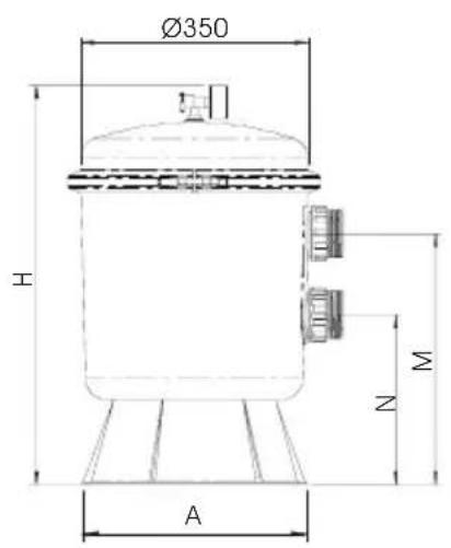
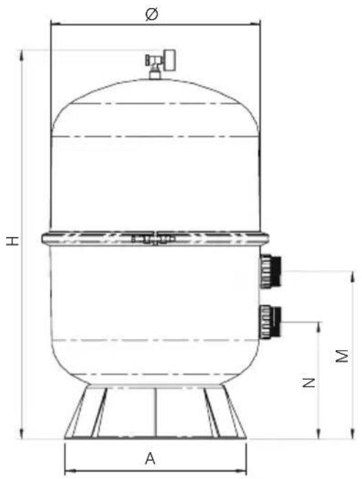
| MODEL / MODELÈ / MODELOMODELO / MODELL / MODELLO | H(mm) | M(mm) | N(mm) | A(mm) |
| ∅ 350 | 615 | 385 | 260 | 344 |
| ∅ 400 840 | 420 | 295 | 341 | |
| ∅ 500 | 940 | 415 | 290 | 450 |
| ∅ 600 985 | 445 | 320 | 450 |
Made in EC
Sacopa, S.A.U.
Pol. Ind. Poliger Sud – Sector I, s/n
- What happens to the water in your pool?
- 1.-"CHEMICAL" TREATMENT
- 2.-"PHYSICAL" TREATMENT
- PH LEVEL
- Why pH is important?
- CHLORINE
- What is understood by free or residual chlorine?
- FILTRATION
- WORKING PRINCIPLES
- ATTENTION
- ASSEMBLY
- SAND LOAD
- BACKWASH
- WASTE
- RINSE
- CLOSED
- START-UP
- SAFETY WARNINGS
- GENERAL TERMS
- INDIVIDUAL TERMS
- LIMITATIONS
- CARGA DE ARENA
- CERRADO
- CARICO DI SABBIA
- "VACIADO" - ESVAZIAR
Brand : ASTRALPOOL
Model : Bilbao
Category : Water filter