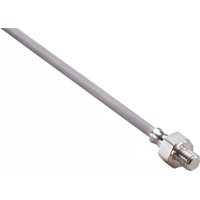
TS285A - Temperature Controller IFM - Free user manual and instructions
Find the device manual for free TS285A IFM in PDF.


User questions about TS285A IFM
0 question about this device. Answer the ones you know or ask your own.
Ask a new question about this device
Download the instructions for your Temperature Controller in PDF format for free! Find your manual TS285A - IFM and take your electronic device back in hand. On this page are published all the documents necessary for the use of your device. TS285A by IFM.
USER MANUAL TS285A IFM
Operating instructions (Ex protection related part)
Temperature sensor
TS285A
1 Safety instructions

Remarks for safe use in hazardous areas.
- The device must only be installed, connected and set up by qualified staff. The qualified staff must have knowledge of types of protection, regulations and provisions for apparatus in hazardous areas.
- The classification and marking of the device must be suitable for the application.
▶ Adhere to the respective national regulations and provisions as well as the relevant installation regulations.
▶ Always comply with the technical data on the type label.
▶ Observe applicable documents.
▶ Provide appropriate safety measures for applications in which the failure of the sensor may lead to a risk for persons.
2 Intended use
This device is used for temperature measurement and is intended for industrial plants.
Use in hazardous areas according to the classification:
| ATEX classification | Identification | Permissible ambient temperature |
| Ex II 3D | Ex tc IIIC T135°C Dc X | -20...115 °C |
| Ex II 3G | Ex ec IIC T4 Gc X | -20...115 °C |
The requirements of the following standards are met:
• EN IEC 60079-0:2018, EN IEC 60079-7:2015/A1:2018, EN 60079-31:2014
3 Installation
Wiring and electrical characteristics: ➞ Technical data and ➞ Device marking
▶ Ensure that no explosive atmosphere is present during any task, e.g. transport, storage, installation, electrical connection, commissioning, maintenance or repair.
▶ Protect device and cable against destruction.
- ▶ Avoid electrostatic charging on plastic housings and cables.
▶ Rubbing the device with non-conductive materials must be strictly avoided.
▶ To avoid electrostatic charging, ensure the equalisation of potential of metal parts (connector housing, fixing elements, protective housing, etc.).
▶ Do not mount the device in the dust flow.
▶ Avoid dust deposits on the device.
▶ Avoid soiling of the connector area.
▶ Connect the device tightly, firmly and securely to the application to be measured in accordance with the state of the art.
▶ Install the device in such a way that the cable and sensor head cannot be twisted against each other.
▶ Ensure that the device has a sufficient heat exchange surface with the medium or object to be measured.
▶ Ensure that faults caused by heat dissipation through the thermowell or the cable are kept to a minimum.
▶ Check whether the supplied fixing accessories are appropriate for the corresponding application with respect to the ATEX requirements. The supplied fixing accessories are not to be considered as a recommendation by the manufacturer for ATEX-conform installation.
- Earthing of the metal sensing head is made via the metal machine chassis which is connected to the sensor.
- Note on the installation in dust atmosphere according to classification II 3D:
The cable end must be protected against the ingress of dust or be located outside the hazardous area.
3.1 Special conditions for safe operation
▶ Avoid direct exposure to high levels of UV light (sunlight). Mount the device in a protected place.
▶ Install devices without direct earthing in an earthed metallic system ensuring a permanent electrical connection so that earthing is indirect.
The device is designed for a low risk of mechanical damage.
▶ Install the cable in a fixed position.
▶ Take appropriate measures to effectively protect the sensor housing and cable from mechanical stress and damage.
▶ During installation, removal, and operation of the sensor, ensure that no tensile or shear forces greater than F = 20 newtons are transmitted between the cable and the sensor housing.
For applications in protection concept ec:
▶ Only operate the device in an environment which ensures pollution degree 2 or higher according to IEC 60664-1.
4 Electrical connection

The unit must be connected by a qualified electrician.
▶ Observe the national and international regulations for the installation of electrical equipment.
▶ Disconnect power.
▶ Connect the unit as follows:

Fig. 1: Core colours: WH = white; RD = red
Observe the following during electrical connection:
▶ Ensure that the electrical characteristics of the device are not exceeded:
• Maximum operating voltage: 6 V
• Maximum operating current: 10 mA
• Maximum power: 20 mW
▶ Connect the device to its downstream electronics safely and permanently.
▶ Protect the cable effectively against damage. Abrasion or sharp-edged objects might damage the cable. This can lead to failure of the device or make ATEX-conform operation impossible.
▶ Install the cable in a fixed position. Minimum bending radius: 15 x cable diameter.
▶ Ensure that the cable is not bent or kinked at the outlet of the metal sensor housing.
▶ Connect the device's connection cable only to power supply for passive resistance sensors in accordance with DIN EN 60751 that are intended for this purpose and approved for the operation of the system.
5 Maintenance, repair and disposal
▶ Clean the device with a damp cloth only.
▶ No modifications or repairs may be made to the device.
▶ In case of a fault please contact the manufacturer.
▶ If required, request data sheets or type examination certificates / certificates from the manufacturer (→ cover sheet / back).
Brand : IFM
Model : TS285A
Category : Temperature Controller