Power Split 2100 V - Log splitter Texas - Free user manual and instructions
Find the device manual for free Power Split 2100 V Texas in PDF.
| Product type | Log splitter |
| Brand | Texas |
| Model | Power Split 2100 V |
| Engine | Texas TG725B, 212 cm³ |
| Maximum pressure | 20 tons |
| Hydraulic reservoir capacity | 14.5 liters |
| Hydraulic oil type | 10wt AW32, ASLE H-150 or ISO32 |
| Number of control levers | 2 (A and B) |
| Recommended log length | 25 to 61 cm |
| Recommended log diameter | 20 to 40 cm |
| Maximum log weight | 45 kg |
| Hydraulic cylinder bore | 11.5 cm |
| Net weight | 246 kg |
| Maximum towing speed | 30 km/h |
| Fuel | Unleaded gasoline, octane rating ≥86 |
| Engine oil | SAE 30, capacity 0.6 L |
| Wood lifting function | Yes, with lifting bar and chain |
| Log securing device | Yes, adjustable on left lever |
| Operating position | Vertical only |
| Routine maintenance | Lubricate beam, check hoses and fittings |
| Spare parts | Available at www.texas.dk |
| Safety standards | CE, EN ISO 12100:2010, EN 609‑1:2017, EN 349:1993+A1:2008 |
| Usage | Outdoor only |
Frequently Asked Questions - Power Split 2100 V Texas
User questions about Power Split 2100 V Texas
0 question about this device. Answer the ones you know or ask your own.
Ask a new question about this device
Download the instructions for your Log splitter in PDF format for free! Find your manual Power Split 2100 V - Texas and take your electronic device back in hand. On this page are published all the documents necessary for the use of your device. Power Split 2100 V by Texas.
USER MANUAL Power Split 2100 V Texas
GB Original user manual
text_image
Technical diagram of a mechanical device with numbered components for identificationtext_image
Technical diagram of a mechanical assembly with numbered components for identificationtext_image
Technical diagram of a mechanical device with numbered components and labeled partsTrin 3:
text_image
Technical diagram showing two installation methods with checkmarks and red/green labels indicating failure or rejection conditions.natural_image
Warning symbol depicting a shield with hand and tools inside a triangle (no text)text_image
Technical diagram of a mechanical device with labeled components A and B, showing structural connections and motion indicators.
natural_image
Close-up of a mechanical device with a yellow cylindrical component inserted into a circular base, surrounded by grass and chains (no visible text or symbols)natural_image
Mechanical assembly diagram showing a chain link and bracket with bolts (no text or symbols)
natural_image
Technical line drawing of a mechanical clamp or bracket assembly (no text or symbols)natural_image
Technical line drawing of a mechanical device with cylindrical components and attached tubing (no text or symbols)
natural_image
Technical line drawing of a mechanical device with no visible text or symbols
natural_image
Technical line drawing of a mechanical device with cylindrical tank and attached cart (no text or symbols)Brug af træholder
natural_image
Two outdoor scenes: one showing a wooden log being cut by a mechanical device, the other showing a tree stump being installed with a tool (no visible text or symbols)natural_image
Technical line drawing of a mechanical device with no visible text or symbols
natural_image
Technical line drawing of a mechanical assembly with curved components and motion arrows (no text or symbols)MÅ IKKE BRUGES VANDRET
natural_image
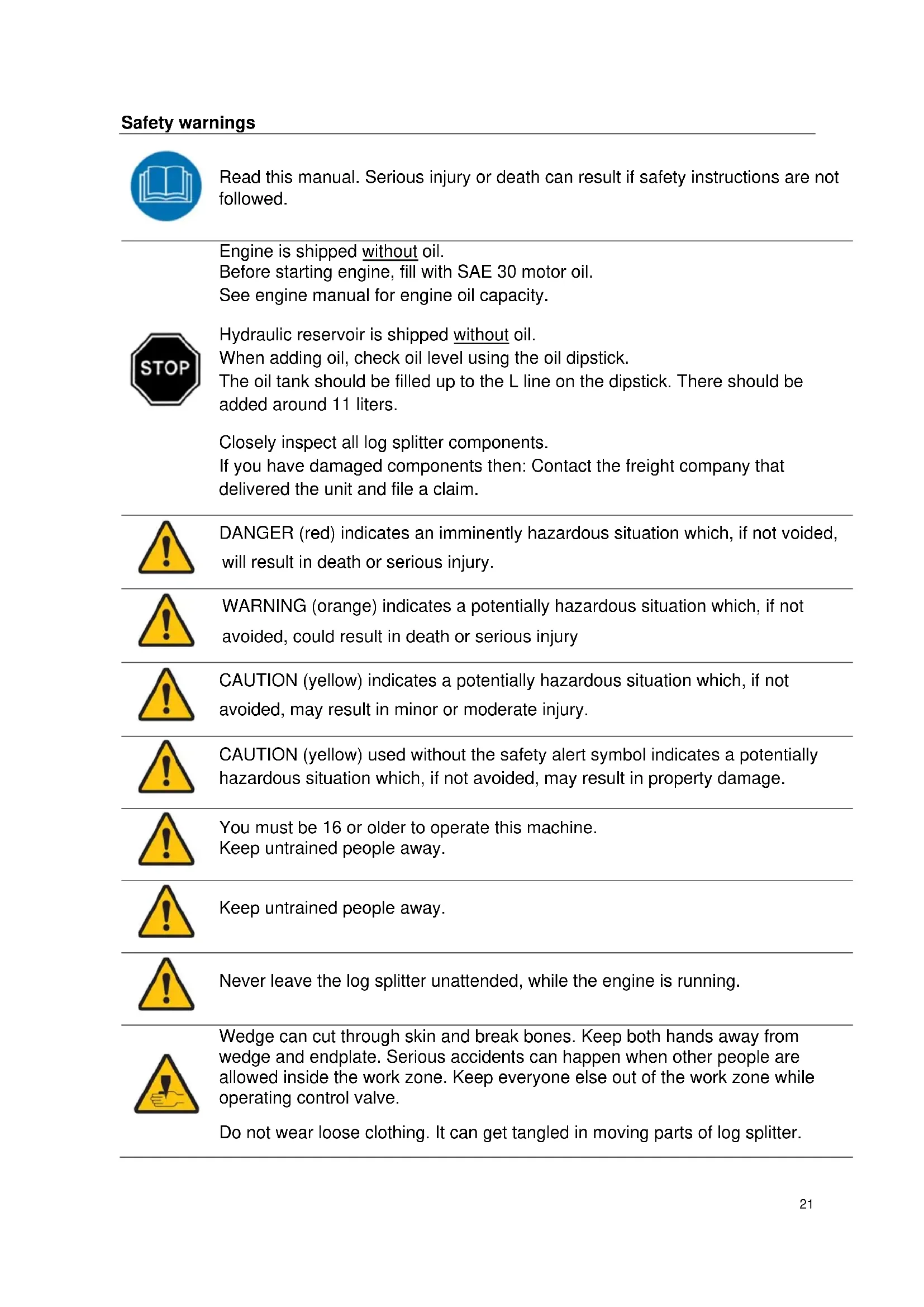
Technical line drawing of a mechanical agricultural machine with no visible text or symbolsSafety warnings....20
Engine is shipped without oil. 21
Identification of parts....24
Assembly 25
Important warnings before start....28
Operation....31
Use of wood lifter 32
Use of log fixture....33
Removal of pinched wood 33
Adjustment of coupling point for control handle B....34
For vehicle towing....34
Maintain and storage 36
Troubleshooting....36
Specifications 37
EC declaration of conformity....77
Spare parts
Parts list and explosive drawings for the specific product, can be found on our website www.texas.dk
If you can find part numbers yourself, this will speed up the service.
To purchase spare parts, please contact your dealer.
REMEMBER TO ADD HYDRAULIC OIL AND ENGINE OIL BEFORE USE!
Safety warnings

Read this manual. Serious injury or death can result if safety instructions are not followed.

Engine is shipped without oil. Before starting engine, fill with SAE 30 motor oil. See engine manual for engine oil capacity.
Hydraulic reservoir is shipped without oil. When adding oil, check oil level using the oil dipstick. The oil tank should be filled up to the L line on the dipstick. There should be added around 11 liters.
Closely inspect all log splitter components. If you have damaged components then: Contact the freight company that delivered the unit and file a claim.

DANGER (red) indicates an imminently hazardous situation which, if not voided, will result in death or serious injury.

WARNING (orange) indicates a potentially hazardous situation which, if not avoided, could result in death or serious injury

CAUTION (yellow) indicates a potentially hazardous situation which, if not avoided, may result in minor or moderate injury.

CAUTION (yellow) used without the safety alert symbol indicates a potentially hazardous situation which, if not avoided, may result in property damage.

You must be 16 or older to operate this machine. Keep untrained people away.

Keep untrained people away.

Never leave the log splitter unattended, while the engine is running.

Wedge can cut through skin and break bones. Keep both hands away from wedge and endplate. Serious accidents can happen when other people are allowed inside the work zone. Keep everyone else out of the work zone while operating control valve.
Do not wear loose clothing. It can get tangled in moving parts of log splitter.

Never wear loose clothing, which can get caught in the moving parts of the log splitter.

Only operate the log splitter in daylight.

Pieces of log may fly out while splitting. Wear safety glasses. Serious eye injury can occur.

High pressure fluid can inject under skin resulting in serious injury including amputation.

Make sure all fittings are tight before applying pressure. Relieve system pressure before servicing.

Do not check for leaks with hand. Instead, use a piece of cardboard to check for leaks.

If skin injection happens, seek immediate "Surgical Treatment".
Serious injury or death can occur if towing safety rules are not followed.

Review towing safety warnings in your towing vehicle manual.

Drive safely. Be aware of the added length of the log splitter.

Never ride or transport cargo on the log splitter.

Drive the vehicle with the log splitter securely attached.

Turn off the vehicle before leaving the log splitter unattended.

Choose a level surface to operate the log splitter.

Block the log splitter wheels to prevent unintended movement.

Never tow or operate this splitter while under the influence of alcohol, drugs, or medication.

Risk of fire and explosion.
Hot exhaust fumes from engine can cause fire. Gasoline is highly flammable and explosive. You can be burned or seriously injured when handling fuel.

Position muffler at least 7 feet from combustible objects.

Before adding fuel, stop the engine and keep heat, sparks, and flame away. Do not add fuel when engine is running or still hot. No smoking near engine.

Do not pump fuel directly into engine at gas station. Static charge can build and ignite fuel. Use a safety approved fuel container to transfer gas to the engine. Wipe up fuel spills immediately.

Only store and handle fuel outdoors. Gasoline vapors can ignite if they collect inside an enclosure. Explosion can result.

Do not change or add to exhaust system. Fire can result.

Do not change or add fuel tanks or fuel lines. Fire can result.

Before each use, check fuel tank and fuel lines for leaks. Any fuel leak is a fire hazard. Fix any fuel leaks before starting engine.

During transportation take precautions to make sure machine will not tip over and cause a fuel leak fire hazard.

Poisonous fumes from engine can kill you. Do not operate indoors even if Ventilated. For outdoor use only.

You can be burned by muffler. Do not touch.
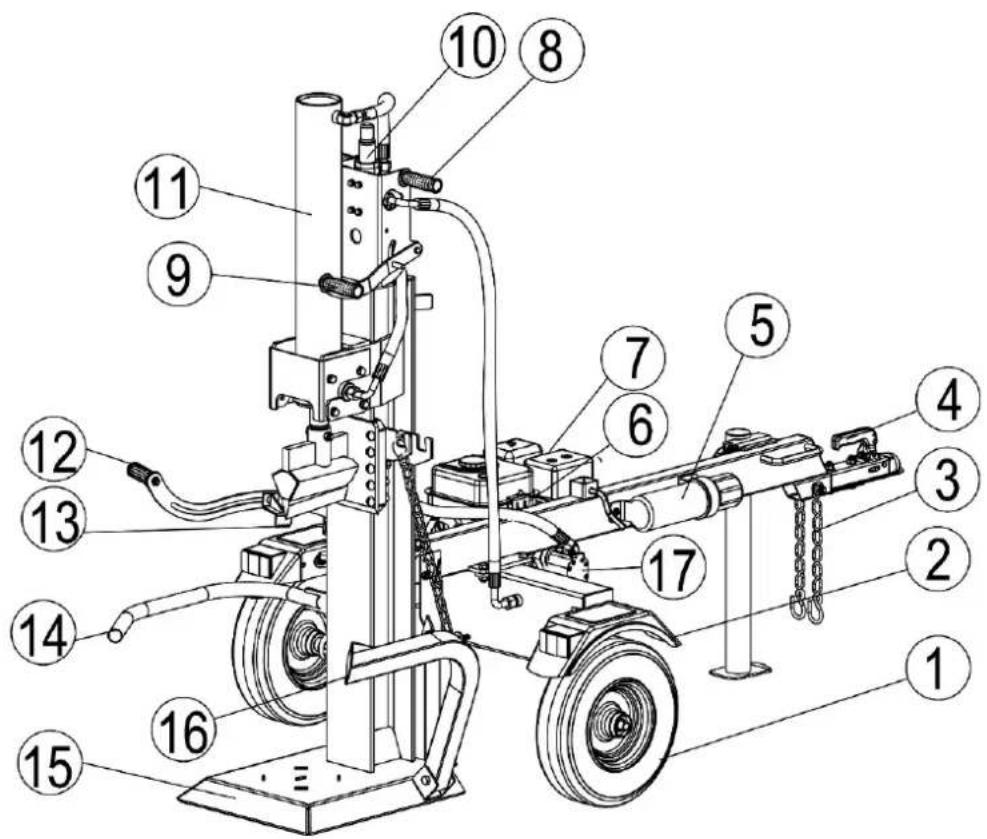
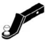
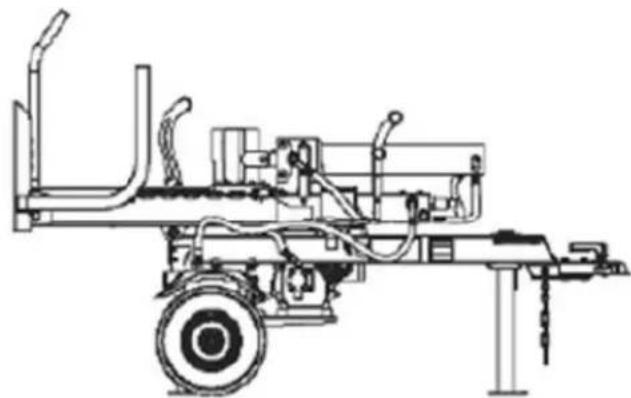
text_image
Technical diagram of a mechanical device with numbered components for identification- Tire / Wheel Assembly
- Fenders
- Safety Chains
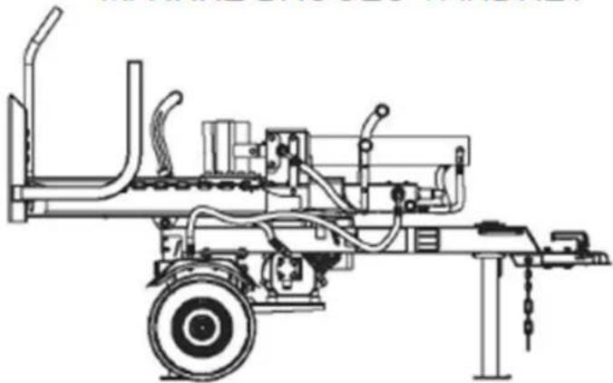
- 50mm Coupler
- Manual Canister
- Switch
- Engine
- Rotate Handle
- Split Control Handle A
- Control Valve
- Cylinder
- Split Control Handle B
- Log Fixture
- Log Cradle
- Base plate / Beam
- Lifting bar
- Gear Pump
Open Shipping Crate
- Set the shipping Crate on a solid, flat surface.
- Carefully cut the shipping bands and remove lid of shipping crate.
- Using two people to lift all parts out of the box
- Locate all hardware before beginning assembly.
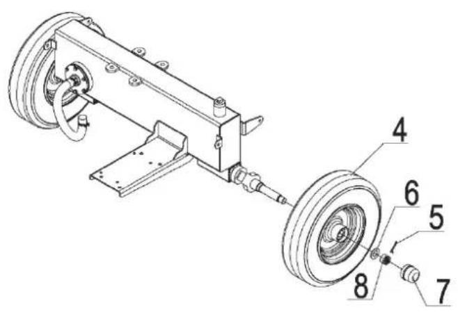 | Step 1Wheel Assembly1. Attach the wheels (#4) to the wheel stand secure using flat washer ∅20 (#6), thin hex slotted nut M20x1.5 (#8) and cotter pin ∅4x36 (#5). Install the axle cap (#7) on the end using rubber hammer. |
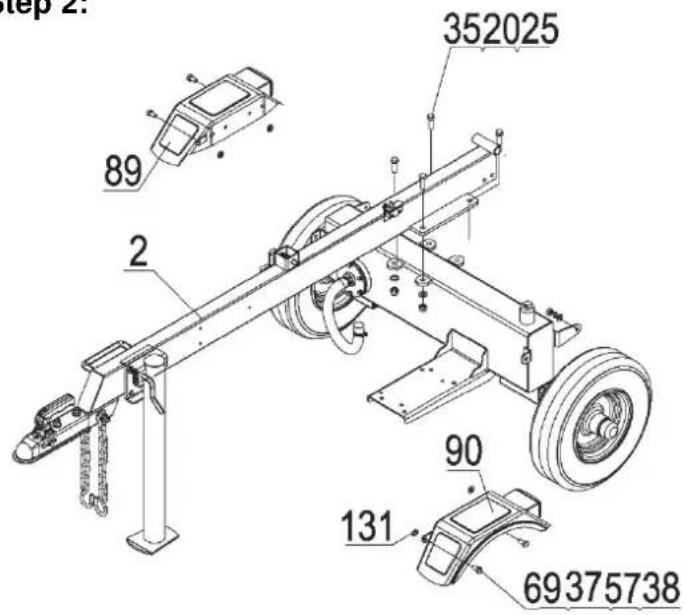 | Attach Tow bar and Support Leg1. Attach the tow bar (#2) to the hydraulic reservoir using hex bolt M12x35 (#35), flat washer ∅12 (#20) and hex lock nut M12 (#25).2. Attach fenders (#89 & #90) to the hydraulic reservoir using hex bolt M8x25 (#69), flat washer ∅8 (#37), lock washer ∅8 (#57) and hex lock nut M8 (#38). Attach rubber washer (#131) between fender and hydraulic reservoir. |
text_image
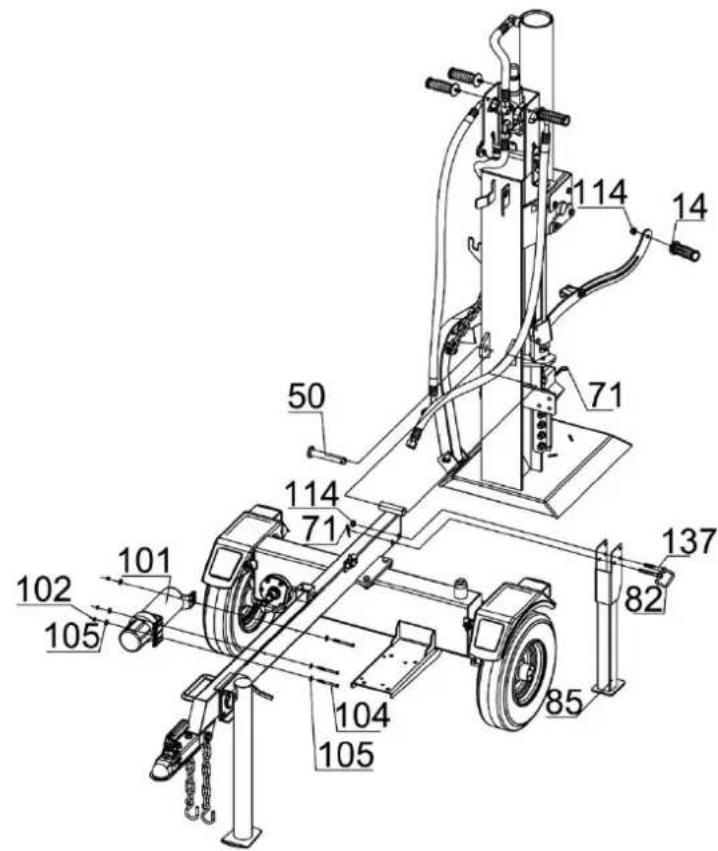
Technical diagram of a mechanical device with numbered components and labeled partsStep 3:
Attach Beam and Manual Canister
- Attach the beam to the tow bar using Hitch Pin (#50) and R Pin (#71).
- Attach rear support leg (#85) to the tow bar using hex bolt M10x70(#137) and hex lock nut M10 (#114). When standing, secure the beam with a pull handle (#82) and an R pin (#71).
- Remove hex bolt M6x65 (#104), large flat washer ∅6 (#105) and nylon lock nut M6 (#102) from tow bar, secure manual canister (#101) to the tow bar by items #104, #105 and #102.
- Attach two plastic handles (#14) to the control handle and two plastic handles (#14) to the beam control valve mounting plate by hex lock nut M10 (#114).
text_image
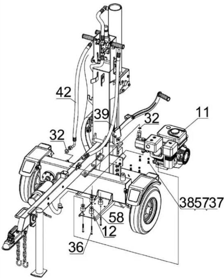
42 39 32 11 385737 58 12 36Step 4:
Attach Engine and the Oil Pipe
- Attach the engine (#11) to the wheel stand using polyurethane block (#12) and large flat washer ∅10 (#58), hex bolt M8x65 (#36), flat washer ∅8(#37), lock washer ∅8 (#57), hex lock nut M8 (#38).
- Attach the clear oil pipe (#43) to the gear pump oil inlet connector, positioning by clamp (#44).
- Attach the high pressure oil pipe (#39) to the gear pump oil outlet connector, sealing with O ring ∅14x2.5 (#32).
- Attach hydraulic hose (#42) to hydraulic reservoir connector, sealing with O ring ∅14x2.5 (#32).
Note: Tighten hydraulic hose connector between torque of 80-90N·m. Adjust the hydraulic hose to a non-kinked state and the connector should be upright.
natural_image
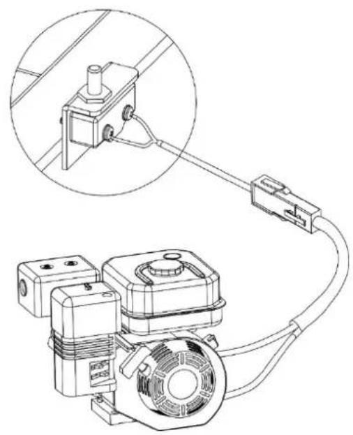
Technical line drawing of an electrical circuit with motor, coil, and connector (no text or symbols)Step 5: Electric Breaking Switch
- Connect the wires of engine and electric breaking switch using quick connector.
text_image
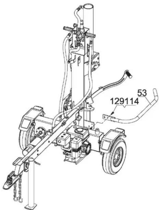
129114 53Step 6: Attach the Log Cradle
- Attach log cradle (#53) to the beam using hex bolt M10x35 (#129) and hex lock nut M10 (#114). The tightness is appropriate for log cradle rotation.
Step 7:
Add engine oil (0.6L SAE30)
- Make sure the log splitter is on a level surface.
- Remove oil fill cap to add oil.
- Refer to the separate owner's engine manual for the amount needed of SAE10W-30 engine oil; replace oil fill cap/dipstick.
- Check engine oil level before use and add if needed.
NOTE: During the break-in period check the engine oil level often.
Step 8
Add gasoline to the engine
- Use only clean, fresh, regular unleaded E5 fuel (Octane 98/100).
- DO NOT mix oil with fuel.
- Remove the fuel cap and slowly add fuel to the tank. DO NOT overfill allow approximately 14 inch of space for fuel expansion.
- Screw on the fuel cap and wipe away any spilled fuel.
Step 9
Add hydraulic oil
- The log splitter needs to be on a flat, level surface before adding the hydraulic oil.
- Remove the oil cap from the hydraulic reservoir.
- Add 11 liters of hydraulic oil AW32, AW46 & universal hydraulic oil are all acceptable types of fluid. Automatic transmission fluid should be used when operating in temperatures below 32 degrees (all units are tested and have excess oil in the ram).
- Check the hydraulic oil level.
- Start engine and use the control lever to extend and retract wedge several times to remove air from the lines.
- With the wedge retracted, check hydraulic oil level again and fill if necessary.
Important warnings before start
The log splitter is a tool which, if used wrongly, can cause serious accidents. It is therefore important that you read and understand the user manual before using the tool, especially the safety warnings marked with the symbol:

The log splitter is only intended for splitting logs of wood, if the size corresponds to the recommended indicates: Length 25-61 cm. Diameter 20-40 cm.
⚠ DO NOT at any time carry passengers, sit or stand on the log splitter.
Check the hydraulic oil level and visually inspect all hoses and attachments for problems.
⚠️ Inspect the engine and make sure the engine oil level is correct.
Before towing the log splitter the tires need to be fully inflated.
Refer to the vehicle owner's manual for proper safety and towing instructions.
The log splitter must (except from the operator) have at least 5 m of clearance to people or animals. It needs to be on a dry and level surface with good footing. Do not work on mud, ice, brush or snow. When using the log splitter, the work zone must always be maintained.
NOTE: Serious accidents can happen when other people are allowed inside the work zone. Keep everyone else outside the work zone while operating the control lever.
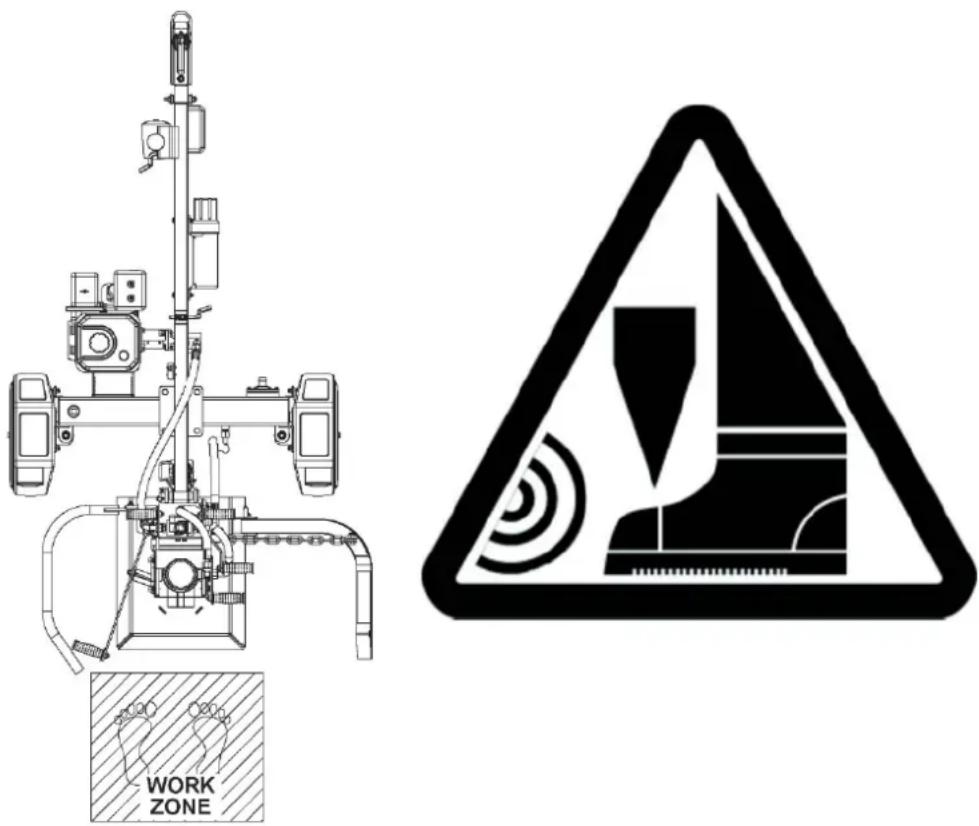
Always keep your feet away from the splitting plate. The feet must always be kept within the WORK ZONE while working with the log splitter. Never kick wood that is standing on the splitting plate, while holding the handles and the wedge runs down. This can result in jam and serious injury. Always release both handles before the feet leave the work zone.
text_image
WORK ZONEAlways keep the work zone clean and free of splitted wood and debris.
Always wear safety gear, eye protection, gloves and work boots when operating the log splitter
The hydraulic oil needs to be above 0^ C before starting the engine. Cold hydraulic oil can damage the hydraulic pump. If outdoor air temperature is below 0^ C allow the log splitter to warm up by extending and returning the wedge several times before splitting wood.
Put both support legs in the down position to prevent the log splitter from moving during operation and block both tires.
Load a log onto the beam against the base plate.
text_image
Technical diagram showing two installation steps with checkmarks and red/green labels indicating status indicators.Keep hands away from all moving parts around wedge head and piston. This also applies when the wedge / piston returns. If a piece of wood is stuck on the wedge, there is a risk that it will be pulled up so that hands / fingers can be pinched between the wood and the protective guard at the starting position of the wedge.

natural_image
Warning symbol depicting a shield with hand and gear, enclosed in a triangle (no text)A Wood, unlike most other materials, is very varied and can behave differently when splitting depending on the type of wood, moisture and whether it has many knots and side branches. Most wood is easily cleaved without problems. However, in some cases, the wood can be very hard, and the log splitter must build up extra pressure before the wood splits. This can mean that the wood "jumps" and divides with high pressure. The same can apply if the tree has many knots.

Note: The log splitter may only be used by one person!
Follow the following procedure:
- Check that the log splitter is stably placed on a firm surface.
-
Put the beam in a vertical position by loosening and removing the locking pin and carefully tipping the base plate down towards the ground. Remember to lock the beam again with the locking pin.
NOTE: The log splitter can only be used in a vertical position. -
Start the engine (see instructions in separate engine operating instructions).
-
Place a piece of wood in the center of the base plate of the log splitter.
-
Activate the control levers A and B with both hands by pressing them down. It causes the piston with the wedge to run down towards the piece of wood. If one or both control levers are released, the wedge stops in the position in which it is located.
text_image
Technical diagram of a mechanical device with labeled components A and B, showing assembly or maintenance setup.
natural_image
Close-up of a mechanical device with a yellow cylindrical component inserted into a circular base, surrounded by grass and chains (no visible text or symbols)-
Let the wedge run down until the wood divides into two parts and release the handles.
-
Push up the right control handle A, which causes the wedge to return.

The log splitter can provide a pressure of approx. 20 tons, which is more than enough to split most wood, even wood that has been stored for time. In the rare cases that the machine cannot split a very hard piece of wood, do not press the cylinder for more than 30 seconds, as the hydraulic oil can otherwise overheat and cause damage to the hydraulic system. In such cases, release the piece of wood and try splitting it in another position (e.g. turn it 90^ ) or skip it.
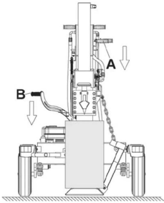
The log splitter is equipped with a wood lifting function, which should be used when splitting long and heavy pieces of wood. The function cannot be used on short pieces.
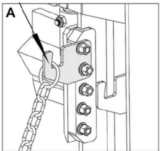
To use the wood lifter, the chain from the lifting bar must be mounted on the holder A. If you do not want to use the lifting function, the chain must be mounted on the holder B.
natural_image
Mechanical assembly diagram showing a chain link and bracket with bolts (no text or symbols)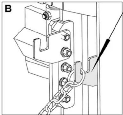
natural_image
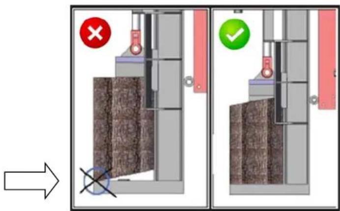
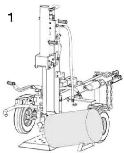
Technical line drawing of a mechanical assembly with chains and bolts (no text or symbols)- Drive the wedge all the way to the bottom so that the lifting bar rests on the ground.
- Place a long piece of wood on the lifting bar and let the wood end rest against the bottom plate (1).
- Activate the right control lever (push up) so that the wedge moves backwards. The chain which is attached to the splitting head and lifting bar now lifts the wood piece up on the base plate (2).
- Split the wood by activating both control levers (3).
natural_image
Technical line drawing of a mechanical device with wheels, pipes, and a cylindrical component (no text or symbols)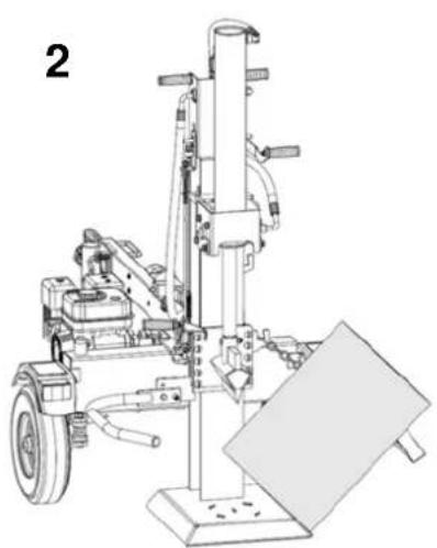
natural_image
Technical line drawing of a mechanical device with wheels and a vertical support structure (no text or symbols)
natural_image
Technical line drawing of a mechanical device with cylindrical tank and vertical railings (no text or symbols)Use of log fixture
On left control handle is a log fixture device which can be held down against the wood. The fixture device can be moved along the handle by loosening the bolt to fit any piece of wood being split. In addition to keeping the wood clamped, it can also be used as a counter-holder for clamped wood.
natural_image
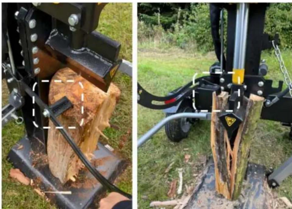
Two outdoor scenes: one showing a wooden log being cut by a machine, the other showing a tree stump being installed with a tool (no visible text or symbols)Removal of pinched wood
If a piece of wood gets stuck on the wedge, remove it as instructed below:
- If the wood is loosely fastened around the wedge, the wooden holder can be used to counter hold when the wood is pulled up by the wedge.
- If the wood is very stuck: Move the wedge up so that the piece of wood is approximately 5-10 cm above the base plate and release the control handles
- Take a heavy tool with a handle, e.g. a large hammer or ax (the back of the head) or just a larger piece of wood and hit it on the wood that is pinched around the wedge. Make sure to keep a good distance with your feet so that they are not hit by the falling wood.
- Turn the piece of wood over and split it again from the opposite side until the wood is completely split.

WARNING: Only the user of the log splitter may loosen a pinched piece of wood. Other people must not help as it can result in dangerous situations.
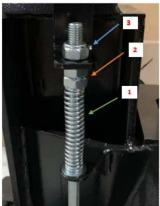
The coupling point for control handle B (12) can be adjusted so that the handle does not have to be pushed down so far to activate the cylinder. To adjust the coupling point, the spring (green arrow 1) must be pressed down using the nuts (orange arrow 2). Start with the lower nut and then the middle nut. Finish by turning the top nut (blue arrow 3) down in level.
text_image
1 2 3
natural_image
Close-up of a mechanical lifting device with yellow and black components, no visible text or symbolsFor vehicle towing
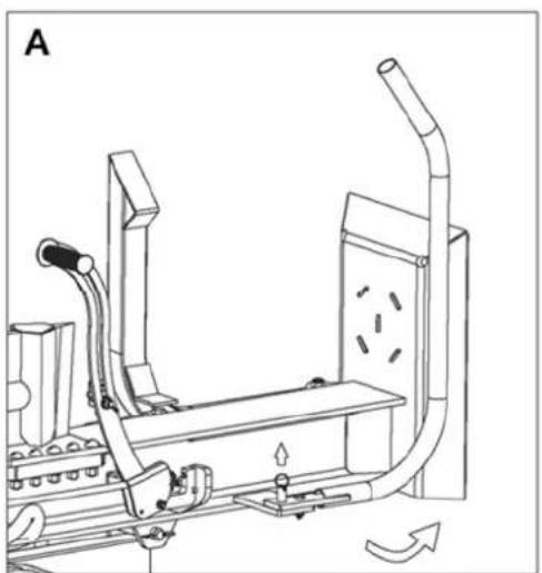
When vehicle towing, pull the log cradle and lifting bar must be put in transport position.
A: Pull the spring pin and push the log cradle in the direction of the arrow and fix the spring pin so it is locked in position.
B: Pull the spring pin and push the lifting bracket in the direction of the arrow and fix the spring pin.
natural_image
Technical line drawing of a mechanical device with pipes and components, no visible text or symbols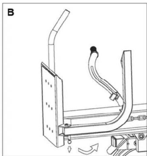
natural_image
Technical line drawing of a mechanical assembly with curved components and motion arrows (no text or symbols)NO HORIZONTAL USE
natural_image
Technical line drawing of a mechanical device with hoses and wheels (no text or symbols)Note: Do not remove the Electric Breaking Swith without permission.
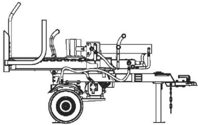
text_image
1. Pull beam lock pin 2. Rotate beam to vertical position by lifting end of beamFOR VEHICLE TOWING
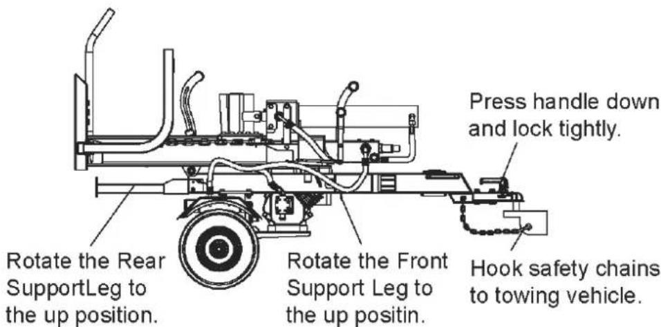
text_image
Press handle down and lock tightly. Rotate the Rear SupportLeg to the up position. Rotate the Front Support Leg to the up positin. Hook safety chains to towing vehicle.Before performing maintenance, the log splitter must be placed in maintenance mode.
- Turn off engine.
- Move the control valve handle forward and backward to relieve hydraulic pressure.
After performing maintenance, make sure all guards, shields, and safety features are put back in place. Failure to follow this warning can result in serious injury.
Refer to the engine owner's manual for engine maintenance.
| What When How | ||
| Hoses Each Use | Inspect for exposed | d wire mesh and leaks.Replaceall worn or damaged hoses before starting engine |
| Hydraulic Fittings | Each Use Inspect | for cracks and leaks. Replace all damaged fittings before starting engine |
| Nuts and Bolts Each Use Check for | loose bolts | |
| Beam Each Use | Apply grease to be | am surface |
| Moving Parts Each Use Clear debris | ||
Troubleshooting
| Problem | |
| Cylinder rod will not move | SOLUTION: A,D,E,H,J |
| Slow cylinder rod speed when extending or retracting | SOLUTION: A,B,C,H,I,K,L |
| Wood will not split or splits extremely slowly | SOLUTION: A,B,C,F,I,K |
| Engine bogs down during splitting | SOLUTION: G,L |
| Engine stalls under low load condition | SOLUTION: D,E,L,M |
| Cause Solution | |
| A-Insufficient oil to pump Check oil level in reservoir | |
| B-Air in oil Check oil level in reservoir | |
| C-Excessive pump inlet vacuum | Check pump inlet hose for blockage or kinks |
| D-Blocked hydraulic lines | Flush and clean the splitter hydraulic system |
| E-Blocked control valve Flush and clean the splitter hydraulic system | |
| F-Low control valve setting Adjust control valve with a pressure gauge | |
| G-High control valve setting Adjust control valve with a pressure gauge | |
| H-Damaged control valve Return control valve for authorized repair | |
| I-Internal control valve leak Return control valve for authorized repair | |
| J-Internal cylinder leak Return cylinder for authorized repair | |
| K-Internally damaged cylinder Return cylinder for authorized repair | |
| L-Engine Control out of adjustment Adjust idle control nuts | |
| M-Engine is loaded during idle down mode | Use shorter log length (24” or less) to allow engine to speed up before contact. |
Specifications
| Model Power Split 2100 V | |
| Engine Texas TG725B (212 cc). | |
| Maximum Pressure 20 ton | |
| Hydraulic Fluid Capacity Approx. 14,5 liters | |
| Hydraulic Fluid Type | 10wt AW32, ASLE H-150, or ISO32 |
| Maximum Towing Speed | 30 km/h |
| Recommended Log Length 25-61 cm | |
| Recommended Log Diameter | 20-40 cm |
| Maximum Log Weight | 45 kg |
| Hydraulic Cylinder Bore | 11,5 cm |
| Net weight | 246 kg |
The manufacturer reserves the right to make improvements in design and/or changes in specifications at any time without incurring any obligation to install them on units previously sold.
Warn Symbole 39
Übersicht 42
Montage....43
text_image
Technical diagram of a mechanical device with numbered components for identificationtext_image
Technical diagram of a mechanical device with numbered components and labeled partsSchritt 3:
text_image
Technical diagram showing two installation steps with checkmarks and red/green labels indicating failure or rejection conditions.natural_image
Warning symbol depicting a shield with a hand holding a tool, enclosed in a triangle (no text or numbers)text_image
Technical diagram of a mechanical device with labeled components A and B, showing structural connections and motion indicators.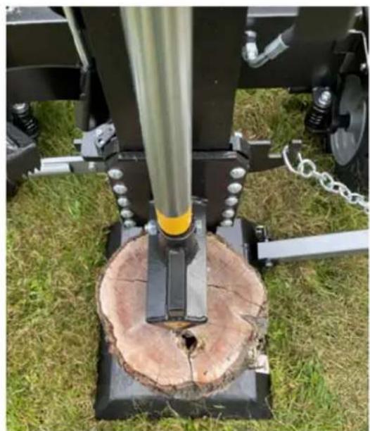
natural_image
Close-up of a mechanical device with a circular base and tree stump, mounted on a metal frame, set on grassy ground (no visible text or symbols)natural_image
Technical diagram of a mechanical assembly with labeled component A, showing chains and bolts (no text or symbols beyond label)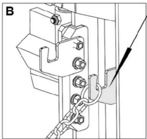
natural_image
Technical line drawing of a mechanical clamp or bracket assembly with chains and bolts (no text or symbols)natural_image
Technical line drawing of a mechanical device with wheels, pipes, and a cylindrical component (no text or symbols)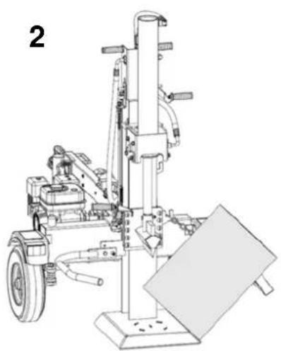
natural_image
Technical line drawing of a mechanical device with no visible text or symbols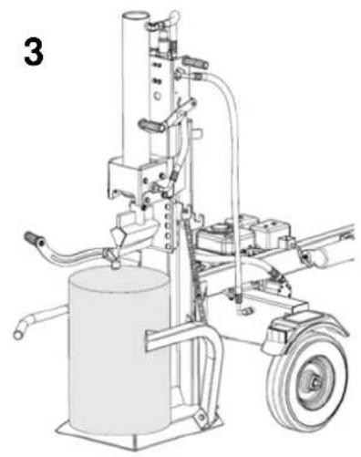
natural_image
Technical line drawing of a mechanical device with cylindrical tank and attached components (no text or symbols)natural_image
Two outdoor scenes showing a wooden stump being cut by a mechanical device, and a tree stump being installed in a grassy field (no visible text or symbols)natural_image
Close-up of a mechanical device with black components and yellow cylindrical component, no visible text or symbolsnatural_image
Technical line drawing of a mechanical device with pipes and components, no visible text or symbols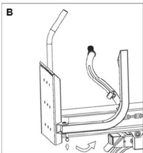
natural_image
Technical line drawing of a mechanical assembly with curved components and directional arrows (no text or symbols)KEINE HORIZONTALE NUTZUNG
natural_image
Technical line drawing of a mechanical device with no visible text or symbolstext_image
Technical diagram of a mechanical device with numbered components for identificationtext_image
Technical diagram of a mechanical device with numbered components and labeled partsPhase 3:
text_image
Technical diagram showing two installation steps with checkmarks and red/green labels indicating status indicators.natural_image
Warning sign depicting a shield with hand and tools, enclosed in a triangle (no text)text_image
Technical diagram of a mechanical device with labeled components A and B, showing structural connections and motion indicators.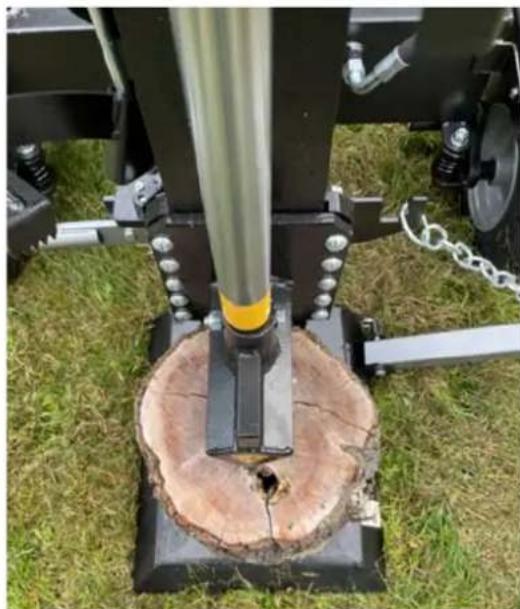
natural_image
Close-up of a mechanical testing setup with a cylindrical tool inserted into a tree stump, surrounded by grass and chains (no visible text or symbols)natural_image
Mechanical assembly diagram showing a chain link and bracket with bolts (no text or symbols)
natural_image
Technical line drawing of a mechanical clamp or bracket assembly with chains and bolts (no text or symbols)natural_image
Technical line drawing of a mechanical device with wheels and components (no text or symbols)
natural_image
Technical line drawing of a mechanical device with no visible text or symbols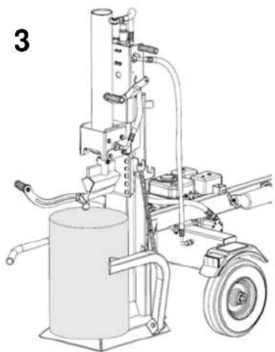
natural_image
Technical line drawing of a mechanical device with cylindrical tank and motor (no text or symbols)natural_image
Two outdoor scenes showing a wooden log being cut by a mechanical device and another tree stump being installed, both with visible cracks and debris (no text or symbols)natural_image
Close-up of a metallic bolt with hexagonal nut and threaded shaft, mounted on black metal frame (no text or symbols visible)
natural_image
Close-up of a mechanical device with black components and yellow vertical tube, no visible text or symbolsnatural_image
Technical line drawing of a mechanical assembly with pipes and components (no text or symbols)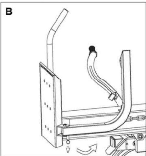
natural_image
Technical line drawing of a mechanical assembly with curved components and directional arrows (no text or symbols)PAS D'UTILISATION HORIZONTALE
natural_image
Technical line drawing of a mechanical device with no visible text or symbolsResponsible for documentation
Johnny Lolk
17.12.2021

text_image
Harry TahnJohnny Lolk
Managing Director