
O3M950 - Lighting IFM - Free user manual and instructions
Find the device manual for free O3M950 IFM in PDF.
| Product type | Infrared lighting |
| Brand | IFM |
| Model | O3M950 |
| Category | Lighting |
| Use | Infrared lighting for optoelectronic systems with IFM 3D sensors |
| Supply voltage | 9..32 V DC |
| Maximum current | Up to 14 A |
| Sensor-lighting mounting distance | 0 to 2.80 m |
| Electrical connector | M12, A-coded, 4-pole |
| Communication interface | MCI (Modulation and Communication Interface) |
| Sensor compatibility | O3M150, O3M160, O3M151, O3M161, O3M250, O3M260, O3M251, O3M261, O3M271 |
| Safety classification | Risk group 1 according to IEC 62471:2006 (invisible infrared light) |
| Protection class | III (SELV) |
| Mounting accessories | U-bracket mounting kit (E3M100/E3M102), round profile kit (E3M103), round profile (E20939/E20941) |
| Required cables | MCI cable (E3M121/E3M122/E3M123), power cable (E3M131/E3M132/E3M133) |
| Delivery contents | O3M950 lighting, brief manual |
| Approvals | CE, EU declaration of conformity available at www.ifm.com |
| Software | Contains Open Source software (GNU license etc.), see www.ifm.com/int/GNU |
Frequently Asked Questions - O3M950 IFM
User questions about O3M950 IFM
0 question about this device. Answer the ones you know or ask your own.
Ask a new question about this device
Download the instructions for your Lighting in PDF format for free! Find your manual O3M950 - IFM and take your electronic device back in hand. On this page are published all the documents necessary for the use of your device. O3M950 by IFM.
USER MANUAL O3M950 IFM
O3M950 O3M960 O3M970
DE
UK
FR
80258599/00 04/2020


natural_image
Simple line drawing of a rectangular frame with a vertical divider (no text or symbols)Inhalt
natural_image
Warning symbol of a sun inside a triangle, set against a solid yellow background (no text or numbers)natural_image
Line drawing of a rectangular electronic device casing with internal compartments and ventilation slots (no text or symbols)DE
flowchart
graph TD
    A["SensorIllumination unit"] --> B["Green checkmark"]
    style A fill:#f9f,stroke:#333
    style B fill:#ccf,stroke:#333
6.1 Montagezubehör
1 About these instructions .... 4
1.1 Symbols used.... 4
1.2 Warnings used 4
2 Safety instructions 4
2.1 Safety note 5
3 Functions and features 6
4 Items supplied....6
5 Accessories....6
6 Installation....7
6.1 Mounting accessory 8
7 Electrical connection....8
7.1 Wiring illumination unit 9
8 Set-up.... 10
8.1 Put the sensor into operation 10
9 Approvals/standards 10
10 Note on the software.... 10


Licences and trademarks
Microsoft ^® , Windows ^® , Windows XP ^® and Windows Vista ^® are registered trademarks of Microsoft Corporation.
Adobe ^® and Acrobat ^® are registered trademarks of Adobe Systems Inc.
All trademarks and company names are subject to the copyright of the respective companies.
1 About these instructions
This document is intended for specialists. These specialists are people who are qualified by their appropriate training and their experience to see risks and to avoid possible hazards that may be caused during operation or maintenance of the device. The document contains information about the correct handling of the device.
Read this document before use to familiarise yourself with operating conditions, installation and operation. Keep this document during the entire duration of use of the device.
For a detailed description of the device please read the operating instructions and the programming manual.
1.1 Symbols used
▶ Instructions
Reaction, result
[...] Designation of keys, buttons or indications
→ Cross-reference

Important note
Non-compliance may result in malfunction or interference.

Information
Supplementary note
1.2 Warnings used
CAUTION
Warning of personal injury.
Slight reversible injuries may result.
2 Safety instructions
These instructions are part of the device. They contain texts and figures concerning the correct handling of the device and must be read before installation or use.
Note the safety instructions. Use the device as intended.
The installation and connection must comply with the applicable national and international standards. Responsibility lies with the person installing the unit.
Only the signals indicated in the technical data or on the device label may be supplied to the connections or wires.
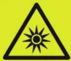
CAUTION
Invisible infrared light
The illumination unit emits infrared light of risk group 1 (IEC 62471:2006) invisible to the human eye.
The infrared light can cause damage to the retina.
▶ Use the illumination unit with the described devices and settings.
▶ Avoid staring into the infrared beam.
▶ Observe the safety note ( 2.1).
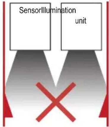
2.1 Safety note
natural_image
Warning symbol of a sun inside a triangle, set against a solid yellow background (no text or numbers)NOTICE IR light emitted from this product.
Classification acc. to IEC 62471:2006 Risk Group 1
3 Functions and features
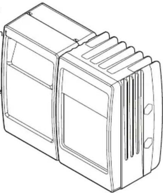
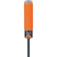
The illumination unit illuminates a scene using infrared light. A sensor processes the infrared light reflected by the surfaces.
The illumination unit may be used as a component of a photoelectric system only with the following devices:
• O3M150 Mobile 3D Sensor
• O3M160 Mobile 3D Sensor
• O3M151 Smart Sensor
• O3M161 Smart Sensor
• O3M250 Mobile 3D Camera
• O3M260 Mobile 3D Camera
• O3M251 Mobile 3D Smart Camera
• O3M261 Mobile 3D Smart Camera
• O3M271 Mobile 3D Smart Camera
4 Items supplied
• O3M950 / O3M960 / O3M970 illumination unit
- Brief instructions

The illumination unit is supplied without sensor, installation and connection accessories and software.
5 Accessories
The following accessories are needed for the operation of the illumination unit:
| Description Article no. | |
| Mobile 3D sensor O3M150 / O3M160 / O3M250 / O3M260 | |
| Smart Sensor O3M151 / O3M161 / O3M251 / O3M261 / | O3M271 |
| MCI connection cable between sensor and illumination unit E3M121 (alternatives: E3M122, E3M123) | |
| Power supply cable for illumination unit E3M131 | (alternatives: E3M132, E3M133) |
You can find more information about the accessories at:
www.ifm.com
6 Installation
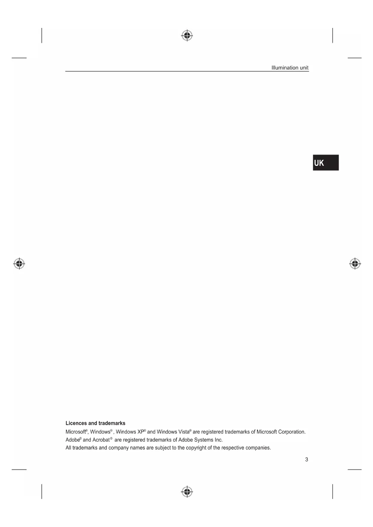
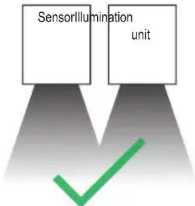
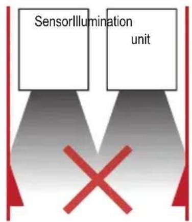
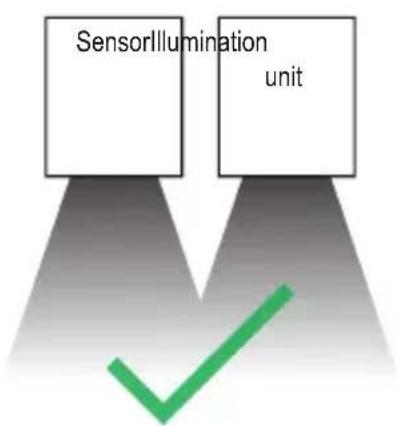
The sensor is operated as a system together with the illumination unit.
During installation note the following:
▶ Operate sensor and illumination unit in combination.
▶ Install sensor and illumination un between 0 and 2.80 m apart.
Select the matching MCI connection cable depending on the distance.
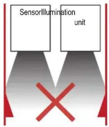
▶ Keep the area illuminated by the illumination unit free from any obstructions in a close range (up to 50 cm).
▶ Use cables with strain relief.
natural_image
Line drawing of a rectangular electronic device casing with internal compartments and ventilation slots (no text or symbols)UK

flowchart
graph TD
    A["SensorIllumination unit"] --> B["Green checkmark"]
    style A fill:#f9f,stroke:#333
    style B fill:#ccf,stroke:#333
flowchart
graph TD
    A["SensorIllumination unit"] --> B["X Symbol"]
    C["SensorIllumination unit"] --> B["X Symbol"]
6.1 Mounting accessory
Depending on the intended location and type of mounting the following mounting accessories are available:
| Description Article no. | |
| Mounting set U-shaped(U-shaped fixture, adjustable for types O3Mxxx) | E3M100 |
| Mounting set U-shaped, black(U-shaped fixture, adjustable for types O3Mxxx) | E3M102 |
| Mounting set for rod mounting ∅ 14 mm(clamp and bracket for types O3Mxxx) | E3M103 |
| Mounting rod straight ∅ 14 mm, length 130 mm, M12 E20939 | |
| Rod, angled ∅ 14 mm, length 200 mm, M12 E20941 |
You can find more information about the accessories at: www.ifm.com
7 Electrical connection
NOTE
The unit must be connected by a qualified electrician.
Device of protection class III (PC III)
The electric supply must only be made via PELV circuits.
▶ Switch off the power supply before electrical connection.
NOTE
The IP rating given in the data sheet is only guaranteed if the M12 connectors are firmly screwed.
The unit can be damaged by insufficiently tightened M12 connectors.
▶ Firmly screw the M12 connectors to the unit.
flowchart
graph TD
    A["Sensor"] -->|Ethernet| B["CAN-Bus"]
    A -->|Ethernet| C["PC"]
    A -->|Analog video converter| D["CANfox"]
    D -->|USB| E["Power supply"]
    F["Illumination unit"] -->|MCI| A
    F -->|9-32 V DC| D
    F -->|9-32 V DC| D
    D -->|12/24 V DC / 75 VA| E
UK
7.1 Wiring illumination unit
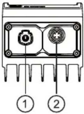 | (1) MCI - Modulation and communication interface | |
| Connection sensor - illumination unit | ||
| Only use original ifm cables E3M121, E3M122 or E3M123. | ||
| (2) Power supply | ||
| M12 connector, A-coded, 4 poles | ||
 | 1 GND2 9..32 V3 9..32 V4 GND | |

Before wiring note the following:
▶ Use all 4 wires of the M12 connector for the power supply.
▶ Unnecessarily long cables cause an additional voltage drop. For the power supply keep the cable short.
▶ Up to 14 A may flow via the cable for the power supply. Ensure a sufficiently dimensioned core cross-section.
▶ Use original ifm cables E3M131, E3M132 or E3M133.
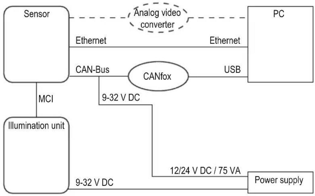
8 Set-up
8.1 Put the sensor into operation
To put the sensor into operation follow the instructions below.
- Switch off the power supply.
- Use MCI cable to connect sensor and illumination unit.
- Connect sensor with Ethernet cable.
- Connect the sensor with the sensor cable for CAN bus and power supply.
The sensor cable connects the power supply and CAN with the sensor.
-
Connect illumination unit with power supply.
-
Connect CANfox USB interface with PC via USB and with CAN via adapter cable.
-
Establish power supply.

During the first set-up the sensor connects with the illumination unit. Connection may take up to 60 s.
9 Approvals/standards
The EU Declaration of Conformity is available on our website:
www.ifm.com
10 Note on the software
This unit contains (maybe modified) Open Source software which is subject to special licensing terms.
For copyright information and licensing terms please refer to: www.ifm.com/int/GNU
For software subject to the GNU General Public License or the GNU Lesser General Public License the source code can be requested against payment of the copying and shipping costs.
Illumination unit
UK


Contenu
natural_image
Warning symbol with black sun inside a triangle on yellow background (no text or numbers)natural_image
Line drawing of a rectangular electronic device casing with internal compartments and ventilation slots (no text or symbols)FR
flowchart
graph TD
    A["SensorIllumination unit"] --> B
    C["Green checkmark"] --> D

- Inhalt
- Montagezubehör
- Licences and trademarks
- About these instructions
- Symbols used
- Warnings used
- CAUTION
- Safety instructions
- Invisible infrared light
- Safety note
- Functions and features
- Items supplied
- Accessories
- Installation
- Mounting accessory
- Electrical connection
- NOTE
- Wiring illumination unit
- Set-up
- Put the sensor into operation
- Approvals/standards
- Note on the software
- Contenu
Brand : IFM
Model : O3M950
Category : Lighting