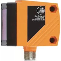
O1D105 - Sensor IFM - Free user manual and instructions
Find the device manual for free O1D105 IFM in PDF.


User questions about O1D105 IFM
0 question about this device. Answer the ones you know or ask your own.
Ask a new question about this device
Download the instructions for your Sensor in PDF format for free! Find your manual O1D105 - IFM and take your electronic device back in hand. On this page are published all the documents necessary for the use of your device. O1D105 by IFM.
USER MANUAL O1D105 IFM
CE
Operating instructions Optical distance sensor
O1D105
GB

Content
1 Preliminary note....4
1.1 Symbols used ....4
1.2 Warning signs used ....4
2 Safety instructions ....4
3 Functions and features....6
3.1 Applications ......6
4 Functions....6
4.1 Output function hysteresis....6
4.2 Output function window 6
4.3 Analogue output function 6
4.4 Switch off the laser 6
5 Installation....7
5.1 Installation conditions ....7
5.2 Mounting accessories....7
6 Electrical connection....8
6.1 Operation with IO-Link master 8
7 Operating and display elements 9
8 Menu....10
8.1 Menu structure....10
8.2 Explanation of the menu....11
9 Operating modes 13
9.1 Run mode 13
9.2 Display mode....13
9.3 Object reflectivity 13
9.4 Programming mode 13
10 Parameter setting 14
10.1 Parameter setting in general ..... 14
10.1.1 Setting of the parameter value 14
10.1.2 Change from menu level 1 to menu level 2....15
10.1.3 Electronic lock 15
10.2 Configuration of the basic settings 16
10.2.1 Selection of the display unit....16
10.2.2 Setting of the display 16
10.2.3 Configuration of OUT1....16
10.2.4 Hysteresis function 17
10.2.5 Setting of the switch point for hysteresis function OUT1 .... 18
10.2.6 Window function 18
10.2.7 Setting of the switch points for window function OUT1 19
10.2.8 Configuration of OUT1....20
10.2.9 Setting of the switch point for hysteresis function OUT2....20
10.2.10 Setting of the switch points for window function OUT2 .....20
10.2.11 Scaling of the measuring range (analogue output)....20
10.3 Teach mode 22
10.3.1 Setting of the sampling rate....22
10.3.2 Setting of the repeatability 22
10.3.3 Table repeatability and accuracy 23
10.4 Extended functions 24
10.4.1 Setting of the time delay for switching outputs 24
10.4.2 Setting of the fault suppression time for switching outputs / analogue output 24
10.4.3 Reset of all parameters to factory setting....24
10.4.4 Display of the software version number 24
11 IO-Link 25
11.1 General information 25
11.2 Device-specific information 25
11.3 Parameter setting tools....25
11.4 Extended functions ......25
11.4.1 Teach function....25
11.4.2 Object reflectivity 25
12 Set-up / operation....25
12.1 Fault indication 26
13 Maintenance, repair and disposal....27
14 Factory setting 27
1 Preliminary note
1.1 Symbols used
▶ Instruction
▷ Reaction, result
[...] Designation of pushbuttons, buttons or indications
→ Cross-reference

Important note
Non-compliance can result in malfunctions or interference.

Information
Supplementary note.
1.2 Warning signs used

WARNING
Warning of serious personal injury.
Death or serious irreversible injuries may result.
2 Safety instructions
- Please read this document prior to set-up of the unit. Ensure that the product is suitable for your application without any restrictions.
- Improper or non-intended use may lead to malfunctions of the unit or to unwanted effects in your application. That is why installation, electrical connection, set-up, operation and maintenance of the unit must only be carried out by qualified personnel authorised by the machine operator.
- In case of malfunction of the unit please contact the manufacturer. If the unit is tampered with and/or modified, any liability and warranty is excluded.
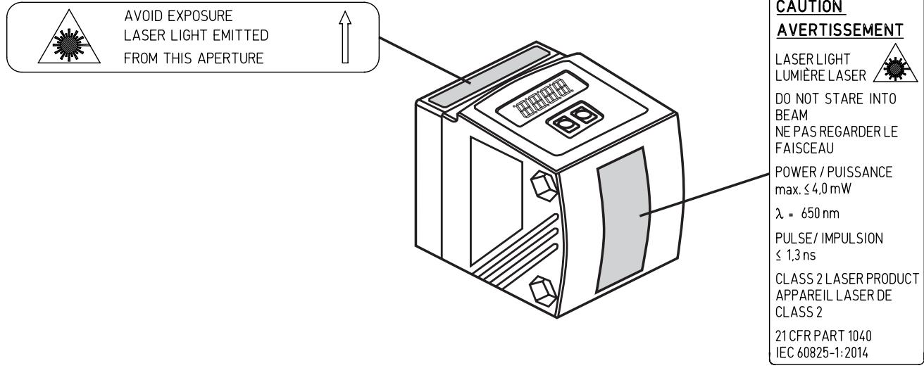
Visible laser light; laser protection class 2.
Use of controls or adjustments other than those specified herein may result in hazardous radiation exposure. Damage to the retina is possible.
▶ Do not stare into the laser beam!
▶ Apply the enclosed labels (laser warning) in the immediate vicinity of the unit.
▶ Adhere to the caution and warning notes on the product label.
▶ Use the enclosed label for the power supply cable.
▶ EN/IEC 60825-1 : 2007 and EN/IEC 60825-1 : 2014
Complies with 21 CFR 1040.10 except for conformance with IEC 60825-1 Ed. 3., as described in Laser Notice No. 56, dated May 8, 2019.
Label for supply cable
ATTACH TO CABLE

ifm electronic gmbh
WARNING:
CLASS 2 LASER PRODUCT DO NOT STARE INTO BEAM
- AVOID EXPOSURE
- UNPLUG CONNECTOR TO
EXTINGUISH LASER BEAM
D-45127 ESSEN
Product label
3 Functions and features
The unit is used as an optical distance sensor.
3.1 Applications
• The optical distance sensor measures distances between 0.2 and 10 m.
- It has a background suppression at > 10...100 m.
- The measured value is shown in a 10-segment display.
- According to the set output functions 2 output signals can be generated.
4 Functions
4.1 Output function hysteresis
The hysteresis keeps the switching state of the output stable if the measured value varies about the sensing range. Both outputs (OUT1 and OUT2) can be set as hysteresis function. → 10.2.4 Hysteresis function
4.2 Output function window
The window function enables the monitoring of a defined acceptable range. Both outputs (OUT1 and OUT2) can be set as window function. → 10.2.6 Window function
4.3 Analogue output function
The sensor can also output an analogue signal on output 2 (OUT2) which is proportional to the distance. → 10.2.11 Scaling of the measuring range (analogue output)
4.4 Switch off the laser
For safety and maintenance purposes the laser of the unit can be temporarily switched off via the input on pin 5.
| Input signal at pin 5 | Laser |
| Low / not connected | On |
| High | Off |
5 Installation
5.1 Installation conditions
▶ Install the unit so that the object to be detected is within a measuring range of 0.2...10 m.
The unambiguity range of the sensor is fixed to 100 m. Objects within a range > 10...100 m are suppressed.

Reflecting objects in the direct beam path of the sensor - also in the range ▷ 100 m – are to be avoided by the customer. Otherwise the measured values may be ambiguous.
5.2 Mounting accessories
The unit is supplied without mounting accessories.
| Examples of mounting accessories | Art. no. |
| Protective cover O1D | E21133 |
| Mounting set E2D101 + E20938 + E20951 | E21079 |
| Mounting set O1D (for rod mounting ∅ 12 mm) | E2D101 |
| Mounting rod straight ∅ 12 mm / M10 | E20938 |
| Mounting set O1D (for rod mounting ∅ 14 mm) | E2D111 |
| Mounting rod straight ∅ 14 mm / M12 | E20939 |
| Fixture for mounting and fine adjustment of O1D laser units (rod or free-standing; depending on the clamp) | E1D100 |

Example mounting:
1: Mounting set for ∅ 12 mm rod art. no. E2D101
2: Mounting rod straight ∅ 12 mm / M10 art. no. E20938
6 Electrical connection

The unit must be connected by a qualified electrician.
▶ The national and international regulations for the installation of electrical equipment must be adhered to.
▶ Ensure voltage supply according to EN 50178, SELV, PELV.
O1D105: cULus, Supply Class 2
▶ Disconnect power.
▶ Connect the unit as follows:
O1D105 PNP


Core colours of ifm sockets:
1 = BN (brown), 2 = WH (white), 3 = BU (blue), 4 = BK (black), 5 = GR (grey).
6.1 Operation with IO-Link master
The unit is compatible with IO-Link master port class A (type A).

For operation with IO-Link master port class B (type B) observe the following:
As a standard, the unit is not compatible with master port class B (type B).
Pin 2 (OU2) and pin 5 (IN1) are used for manufacturer-specific functions.
That means that the main supply voltage of the unit and the additional voltage supply (master port class B on pins 2/5) are not electrically isolated.
With the following configurations the unit can be used with master port class B:
- Connect unit and IO-Link master via 3 wires: Connect pins 1, 3 and 4 of the unit with the IO-Link master (do not connect pins 2 and 5).
- Connect unit and IO-Link master via 4 wires: Deactivate pin 2 (OU2) via IO-Link (setting OU2 = "off") and connect pins 1, 2, 3 and 4 of the unit with the IO-Link master (do not connect pin 5).
7 Operating and display elements
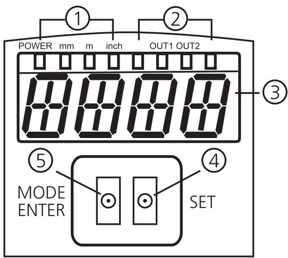
| 1: 4 x LED green | Lighting LED = power and set display unit (mm, m, inch) |
| 2: 4 x LED yellow (two not connected) | Indication of the switching status; lights, if the corresponding output is switched. |
| 3: 4-digit alphanumeric display | Indication of the measured distance, the parameters and parameter values. |
| 4: Programming button [SET] | Setting of the parameter values (scrolling by holding pressed; incrementally by pressing once). |
| 5: Programming button [MODE/ENTER] | Selection of the parameters and acknowledgement of the parameter values. |
8 Menu
8.1 Menu structure

8.2 Explanation of the menu
For the factory settings please refer to the end of these instructions ( → 14 Factory setting).
| OU1 | Configuration for output 14 switching functions can be selected:[Hno], [Hnc], [Fno], [Fnc] → 10.2.3 Configuration of OUT1 |
| SP1 | Switch point for hysteresis function OUT1 Limit value at which the output with selected hysteresis function changes its switching state (object nearer/farther than distance set). [SP1] is only active if [OU1] = [Hno] or [Hnc]. → 10.2.5 Setting of the switch point for hysteresis function OUT1 |
| nSP1FSP1 | Switch points for window function OUT1 Limit values at which the output with selected window function changes its switching state (object present / not present between the distance "near" and the distance "far"). [nSP1] = switch point "near" / [FSP1] = switch point "far". [nSP1] / [FSP1] are only active if [OU1] = [Fno] or [Fnc]. → 10.2.7 Setting of the switch points for window function OUT1 |
| OU2 | Configuration for output 24 switching functions and 2 analogue signals can be selected:[Hno], [Hnc], [Fno], [Fnc], [I], [U] → 10.2.8 Configuration of OUT1 |
| SP2 | Switch point for hysteresis function OUT2 Limit value at which the output with selected hysteresis function changes its switching state (object nearer/farther than distance set). [SP2] is only active if [OU2] = [Hno] or [Hnc]. → 10.2.9 Setting of the switch point for hysteresis function OUT2 |
| nSP2FSP2 | Switch points for window function OUT2 Limit values at which the output with selected window function changes its switching state (object present / not present between the distance "near" and the distance "far"). [nSP2] = switch point "near" / [FSP2] = switch point "far". [nSP2] / [FSP2] are only active if [OU2] = [Fno] or [Fnc]. → 10.2.10 Setting of the switch points for window function OUT2 |
| ASP | Analogue start point Measured value at which 4 mA / 0 V are provided. [ASP] is only active if [OU2] = [I] or [U]. → 10.2.11 Scaling of the measuring range (analogue output) |
| AEP | Analogue end point Measured value at which 20 mA / 10 V are provided. [AEP] is only active if [OU2] = [I] or [U]. → 10.2.11 Scaling of the measuring range (analogue output) |
| TEAC | Teach mode Selection "sampling rate" or "repeatability"→ 10.3 Teach mode |
| EF | Extended functions Press [SET] to open the submenu "Extended functions"→ 10.4 Extended functions |
| dS1dr1dS2dr2 | Delay for the switching outputs[dSx] = switch-on delay; [drx] = switch-off delay. The output does not immediately change its switching status when the switching condition is met but only after the delay has elapsed. If the switching condition is no longer met after the delay has elapsed, the switching status of the output does not change. [dS2] and [dr2] are not effective if [OU2] = [I] or [U]. → 10.4.1 Setting of the time delay for switching outputs |
| dFo | Damping of the measured signal This function allows to suppress short-time saturation of the measuring element (such saturation can result from direct reflection or strong fluctuations in brightness). During the delay set, the latest valid value measured is displayed, the output signals remain unchanged. → 10.4.2 Setting of the fault suppression time for switching outputs / analogue output |
| d15 | Display setting7 settings can be selected:[d1], [d2], [d3], [rd1], [rd2], [rd3], [OFF]→ 10.2.2 Setting of the display |
| Urr | Setting of the display unit Selection of the unit of measurement for [SP1], [SP2], [ASP], [AEP] Selection options: [mm] [m] [inch]→ 10.2.1 Selection of the display unit |
| r-ES | Restore factory setting→ 10.4.3 Reset of all parameters to factory setting |
| SW | Display of the software version number→ 10.4.4 Display of the software version number |
9 Operating modes
9.1 Run mode
The run mode is the normal operating mode.
After power on the unit is in the Run mode. It carries out its monitoring function and generates output signals according to the set parameters.
The display indicates the current distance, the yellow LEDs signal the switching status of the outputs.
9.2 Display mode
Indication of the parameters and the set parameter values.
▶ Press [MODE/ENTER] briefly.
▷ Unit goes to the Display mode. Internally it remains in the operating mode. The set parameter values can be read.
▶ To scroll through the parameters, press [MODE/ENTER] briefly.
▶ To display the respective parameter value, press [SET] briefly.
▷ After 15 s the unit returns to the Run mode.
9.3 Object reflectivity
Display of the object reflectivity (formerly: align mode).
▶ Press [SET] in the Run mode.
▷ The unit displays an orientation value for the object reflectivity (e.g. +100 corresponds to a white object, +020 corresponds to a grey object).
9.4 Programming mode
Setting the parameter values → 10.1 Parameter setting in general.
10 Parameter setting
During parameter setting the unit remains internally in the operating mode. It continues its monitoring function with the existing parameters until the change has been finished.
10.1 Parameter setting in general
10.1.1 Setting of the parameter value

Select the display unit [Uni] before you define the values for the parameters. In case of subsequent changes of the display unit rounding errors during internal conversion to other units may falsify the set values.
→ 10.2.1 Selection of the display unit
| 1 | Selection of the parameter ▶ Press [MODE/ENTER] until the requested parameter is displayed. |  |  | 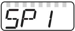 |
| 2 | Setting of the parameter value ▶ Press [SET] and keep it pressed. ▷ The current parameter value flashes for 5 s. ▶ Increase the setting value incrementally by pressing the button once or continuously by pressing it permanently. |  |  | 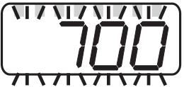  |
| Decrease the value: let the display move to the maximum setting value. Then the cycle starts again at the minimum setting value. | ||||
| 3 | Confirmation of the parameter value ▶ Press [MODE/ENTER] briefly. ▷ The parameter is displayed again; the new parameter value is effective. |  |  |  |
| 4 | Setting of other parameters ▶ Start again with step 1. | |||
| 5 | Finishing the parameter setting ▶ Wait for 15 s or press [MODE/ENTER]. ▷ The current measured value is displayed. | |||
10.1.2 Change from menu level 1 to menu level 2
| ▶ Press [MODE/ENTER] several times until [EF] is displayed. |    |
| ▶ Press [SET] briefly. ▷ The first parameter of the sub-menu is displayed (here: [dr1]). |   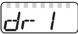 |
10.1.3 Electronic lock
The unit can be locked electronically to prevent unintentional settings. On delivery the unit is not locked.
| Locking▶ Make sure that the unit is in the normal operating mode. ▶ Keep [MODE/ENTER] + [SET] pressed until [Loc] is displayed. ▷ The unit is locked. |    |
| [Loc] is displayed briefly if you try to change parameter values on the locked unit during operation. | |
| Unlocking▶ Keep [MODE/ENTER] + [SET] pressed until [uLoc] is displayed. ▷ The unit is unlocked. |   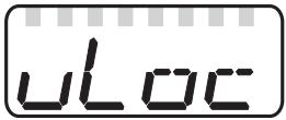 |
Timeout

If no button is pressed for 15 s during the setting procedure, the unit returns to the Run mode with unchanged values.
10.2 Configuration of the basic settings
10.2.1 Selection of the display unit
| Set [Uni] before the values for the parameters [SPx], [nSPx], [FSPx], [ASP], [AEP] are defined. In case of subsequent changes of the display unit rounding errors during internal conversion to other units may falsify the set values. ▶ Change to [EF]. ▶ Select [Uni] and set the unit of measurement. Selection of the unit of measurement: [mm], [m], [inch] ▶ Confirm with [MODE/ENTER]. ▷ The selected unit is indicated by a green LED on the display. | Uni |
10.2.2 Setting of the display
| ▶ Change to [EF]. ▶ Select [diS] and make the settings.7 settings can be selected:·[d1] = update of the measured value every 50 ms.·[d2] = update of the measured value every 200 ms.·[d3] = update of the measured value every 600 ms.·[rd1], [rd2], [rd3] = display like [d1], [d2], [d3] rotated by 180°. The update of the measured value only refers to the display. It has no effect on the outputs.·[OFF] = The measured value display is deactivated in the Run mode. Press one button to indicate the current measured value for 15 s. ▶ Confirm with [MODE/ENTER]. The LEDs remain active even if the display is deactivated. | d, 5 |
10.2.3 Configuration of OUT1
| ▶ Select [OU1] and set the switching functions. Switching functions:• [Hno] = hysteresis function / normally open• [Hnc] = hysteresis function / normally closed• [Fno] = window function / normally open• [Fnc] = window function / normally closed▶ Confirm with [MODE/ENTER]. | OU 1 |
10.2.4 Hysteresis function
The hysteresis keeps the switching state of the output stable if the measured value varies about the sensing range. In either case set and reset points are symmetrically arranged around the selected switch point [SPx]. The hysteresis is the distance between set and reset points; it is calculated on the basis of the repeatability with a safety factor of 1.5. The calculation is based on the repeatability for max. 40 klux. → 10.3.3 Table repeatability and accuracy
Example Hno
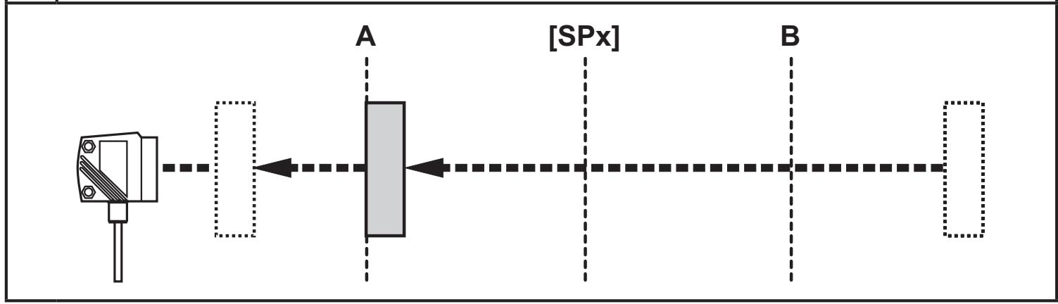
- For the output function [Hno] the output switches when the object approaches and when the switch point (A) is reached.
- When the object is removed again, the output does not switch back before the reset point (B) is exceeded.
The reset point (B) is greater than the set point (A).
1
2

[SPx] = switch point; A = set point; B = reset point
When the output function [Hnc] was selected, set and reset point are reversed. The output is switched off when the object approaches. When the object is removed, the output switches on.
Switching status of the outputs
| Output function | Object distance (D) | Output status |
| [Hno] | D < [SPx] | Closed |
| D > [SPx] | Open | |
| [Hnc] | D < [SPx] | Open |
| D > [SPx] | Closed |
Example of output function [Hno]
Sampling rate 15 Hz, distance to the object 1200 mm, grey value (18 % remission):
Hysteresis = ± 8 mm (repeatability → 10.3.3 table) x factor 1.5 = 12 mm
- Reset point 1200 mm + (12 mm) = 1212 mm
- Set point 1200 mm - (12 mm) = 1188 mm
10.2.5 Setting of the switch point for hysteresis function OUT1
▶ Select the output function [Hno] or [Hnc] at [OU1].
▶ Confirm with [MODE/ENTER].
▶ Select [SP1] and set the switch point.
▶ Confirm with [MODE/ENTER].
0U 1
SP1
10.2.6 Window function
It is possible to define a window for the object recognition for each of the two outputs (OUT1 / OUT2).
Switches off when the object is detected

[nSPx] = switch point "near"; [FSPx] = switch point "far"; FE = window
If the measured value is between the switch point "near" [nSPx] and the switch point "far" [FSPx], the output is open (when [OUx] = [Fnc]).
Switches when the object is detected

[nSPx] = switch point "near"; [FSPx] = switch point "far"; FE = window
If the measured value is between the switch point "near" [nSPx] and the switch point "far" [FSPx], the output is closed (when [OUx] = [Fno]).
Switching status of the outputs
| Output function | Object distance (D) | Output status |
| [Fno] | D < [nSPx] | Open |
| D > [FSPx] | ||
| [nSPx] < D < [FSPx] | Closed | |
| [Fnc] | D < [nSPx] | Closed |
| D > [FSPx] | ||
| [nSPx] < D < [FSPx] | Open | |
| Both window limit values ([nSPx] and [FSPx]) work with a switching hysteresis → 10.2.4 Hysteresis function / example of the output function [Hno]. | ||
10.2.7 Setting of the switch points for window function OUT1
| ▶ Select the output function [Fno] or [Fnc] at [OU1]. ▶ Confirm with [MODE/ENTER]. ▶ Select [nSP1] and set the switch point "near". ▶ Confirm with [MODE/ENTER]. ▶ Select [FSP1] and set the switch point "far". ▶ Confirm with [MODE/ENTER]. | OU 1nSP 1FSP 1 |
10.2.8 Configuration of OUT1
| ▶ Select [OU2]. ▶ Set the switching functions or analogue signals:• [Hno] = hysteresis function / normally open• [Hnc] = hysteresis function / normally closed• [Fno] = window function / normally open• [Fnc] = window function / normally closed• [I] = current output analogue 4...20 mA• [U] = voltage output analogue 0...10 V▶ Confirm with [MODE/ENTER]. | OU2 |
10.2.9 Setting of the switch point for hysteresis function OUT2
| ▶ Select [Hno] or [Hnc] at [OU2]. ▶ Confirm with [MODE/ENTER]. ▶ Select [SP2] and set the switch point. ▶ Confirm with [MODE/ENTER]. → 10.2.4 Hysteresis function | OU2SP2 |
10.2.10 Setting of the switch points for window function OUT2
| ▶ Select [Fno] or [Fnc] at [OU2]. ▶ Confirm with [MODE/ENTER]. ▶ Select [nSP2] and set the switch point "near". ▶ Confirm with [MODE/ENTER]. ▶ Select [FSP2] and set the switch point "far". ▶ Confirm with [MODE/ENTER]. → 10.2.6 Window function | OU2nSP2FSP2 |
10.2.11 Scaling of the measuring range (analogue output)
| ▶ Select [I] or [U] at [OU2]. ▶ Confirm with [MODE/ENTER]. ▶ Select [ASP] and set "Analogue start point". With [ASP] you define at which measured value the output signal is 4 mA / 0 V. ▶ Confirm with [MODE/ENTER]. ▶ Select [AEP] and set the "Analogue end point". With [AEP] you define at which measured value the output signal is 20 mA / 10 V. It can also be selected so that it is before [ASP]. This implements a falling edge. ▶ Confirm with [MODE/ENTER]. Minimum distance between [ASP] and [AEP]:100 mmWhen the minimum distance is not reached, the error message "SIZE" is displayed. | OU2ASPAEP |
Current output 4 ... 20 mA
Factory setting

MEW = final value of the measuring range
In the set measuring range the output signal is between 4 and 20 mA.
Faults are also displayed:
Too much light or object too near: 3.5 mA for a rising edge ([ASP] < [AEP]), 20.5 mA for a falling edge ([ASP] > [AEP]).
Object too far or no object present:
20.5 mA for a rising edge; 3.5 mA for a falling edge.
Voltage output 0 ... 10 V
Factory setting

MEW = final value of the measuring range
In the set measuring range the output signal is between 0 and 10V.
10.3 Teach mode
10.3.1 Setting of the sampling rate
| The sampling rate indicates the time after which a new result of measurement is provided and the outputs are updated. The switching frequency is typ. approx. 1/3 of the sampling rate. ▶ Select [TEAC], then press [SET] and keep pressed until [WAIT] is displayed. ▷ [rATE] and [rEPr] are displayed alternately. ▶ When [RATE] is displayed: Press [SET] until the preset measured sampling rate value flashes. ▶ Enter a value incrementally by pressing [SET] once. ▶ Confirm with [MODE/ENTER]. ▷ [WAIT] is displayed while the repeatability [rEPr] is calculated.> The sampling rate [RATE] and the repeatability [rEPr] are displayed alternately. | TEACr-ATE |
10.3.2 Setting of the repeatability
| ▶ Select [TEAC], then press [SET] and keep pressed until [WAIT] is displayed. ▷ [rATE] and [rEPr] are displayed alternately. ▶ When [rEPr] is displayed: Press [SET] until the preset repeatability value flashes. ▶ Enter value incrementally by pressing [SET] once. ▶ Confirm with [MODE/ENTER]. ▷ [WAIT] is displayed while the sampling rate [RATE] is calculated.> The sampling rate [RATE] and the repeatability [rEPr] are displayed alternately. | TEACr-EPr- |
10.3.3 Table repeatability and accuracy
Values for sampling rate 15 Hz, extraneous light of max. 40 klx*
| Distance in [mm] | Repeatability | Accuracy | ||
| white90 % remission | grey18 % remission | white90 % remission | grey18 % remission | |
| 200...1000 | ± 4.5 mm | ± 6.0 mm | ± 15.0 mm | ± 16.0 mm |
| 1000...2000 | ± 5.0 mm | ± 8.0 mm | ± 15.0 mm | ± 18.0 mm |
| 2000...4000 | ± 16.0 mm | ± 19.0 mm | ± 25.0 mm | ± 30.0 mm |
| 4000...6000 | ± 24.0 mm | ± 33.0 mm | ± 35.0 mm | ± 45.0 mm |
| 6000...10000 | ± 50.0 mm | — | ± 65.0 mm | — |
Values for sampling rate 15 Hz, extraneous light of 40...100 klx*
| Distance in [mm] | Repeatability | Accuracy | ||
| white90 % remission | grey18 % remission | white90 % remission | grey18 % remission | |
| 200...2000 | ± 14.0 mm | ± 14.0 mm | ± 24.0 mm | ± 24.0 mm |
| 2000...4000 | ± 25.0 mm | ± 30.0 mm | ± 35.0 mm | ± 40.0 mm |
| 4000...6000 | ± 31.0 mm | ± 45.0 mm | ± 41.0 mm | ± 55.0 mm |
| 6000...10000 | ± 60.0 mm | — | ± 70.0 mm | — |
*Range referred to black (6 % remission) ≤ 4000 mm.
The values apply at:
- constant ambient conditions (23°C / 960 hPa)
- only after unit powered up for 10 minutes
10.4 Extended functions
10.4.1 Setting of the time delay for switching outputs
| ▶ Select [EF]. ▶ Press [SET] to change to the menu [EF]. ▶ Select parameters with [MODE/ENTER]:[dSx] = switch-on delay; [drx] = switch-off delay▶ Set the parameter value with [SET]:Setting range [s]: 0 / 0.1 ... 5 s in steps of 0.1s(0 = delay time is not active)▶ Confirm with [MODE/ENTER]. | EFd51dr1d52dr2 |
10.4.2 Setting of the fault suppression time for switching outputs / analogue output
| ▶ Select [EF]. ▶ Press [SET] to change to the menu [EF]. ▶ Select [dFo] (formely: [dAP]). ▶ Set the parameter value with [SET]:Setting range [s]: 0...0.1...0.2...0.5...1...2...5. ▶ Confirm with [MODE/ENTER]. | EFdFo |

With [dFo], the error types "too much light" and "not enough light" are suppressed ( → 12.1 Fault indication).
10.4.3 Reset of all parameters to factory setting
| ▶ Select [EF]. ▶ Press [SET] to change to the menu [EF]. ▶ Select [rES], then press [SET] and keep it pressed until [----] is displayed. ▶ Confirm with [MODE/ENTER]. ▷ The unit changes to the Run mode. | EFr-ES |
10.4.4 Display of the software version number
| ▶ Select [EF]. ▶ Press [SET] to change to the menu [EF]. ▶ Select [SW], then press [SET]. ▷ The software version number is displayed. ▶ Press [MODE/ENTER] to return to the menu [EF]. | EFSW |
11 IO-Link
11.1 General information
This unit has an IO-Link communication interface which requires an IO-Link-capable module (IO-Link master) for operation.
The IO-Link interface enables direct access to the sensor values and parameters and provides the possibility to set the parameters of the unit during operation.
In addition communication is possible via a point-to-point connection with a USB adapter cable.
You will find more detailed information about IO-Link at www.ifm.com.
11.2 Device-specific information
You will find the IODDs necessary for the configuration of the IO-Link device and detailed information about sensor values, diagnostic information and parameters in the overview table at www.ifm.com.
11.3 Parameter setting tools
You will find all necessary information about the required IO-Link hardware and software at www.ifm.com.
11.4 Extended functions
With IO-Link extended functions and measured data are available.
11.4.1 Teach function
The following teach functions are available:
- Teach on background
- Two-point teaching
The teach functions are described in detail in the IODD.
11.4.2 Object reflectivity
The object reflectivity is provided via the display and as process data value (PDV).

The object reflectivity can, for example, be used to detect sensor soiling.
12 Set-up / operation
▶ After mounting, wiring and programming check whether the unit operates correctly.
▷ If the unit has been correctly set up, the distance to the object is indicated.
12.1 Fault indication
| Display | Possible cause | Switching output | Current output / voltage output | IO-Link process value distance3) | IO-Link process value object reflectivity3) | ||||
| [Hno] | [Hnc] | [Fno] | [Fnc] | [ASP] < [AEP] | [ASP] > [AEP] | ||||
| [++] | too much light, e.g. reflective surface | ON | OFF | OFF | ON | 3,5 mA/0 V | 20,5 mA/10 V | NoData | OL |
| [- -] | too little light, no object | OFF | ON | OFF | ON | 20,5 mA/10 V | 3,5 mA/0 V | NoData | UL |
| [nEAr] | object to be measured outside the measuring range < 0.2 m | ON | OFF | OFF | ON | 3,5 mA/0 V | 20,5 mA/10 V | UL | NoData |
| [FAr] | object to be measured outside the measuring range > 3.5 m | OFF | ON | OFF | ON | 20,5 mA/10 V | 3,5 mA/0 V | OL | NoData |
| [Errp] | plausibility (e.g. object too fast) | X1) | X1) | X1) | X1) | X1) | X1) | X1) | X1) |
| [LoFF] | laser switched off | OFF | ON | OFF | ON | 20,5 mA/10 V | 3,5 mA/0 V | NoData | NoData |
| [SC1] | short circuit in switching output 1 | 2) | 2) | n.a. | n.a. | ||||
| [SC2] | short circuit in switching output 2 | 2) | 2) | X1) | X1) | ||||
| [SC] | short circuit in all switching outputs | n.a. | n.a. | ||||||
1) unchanged
2) [SC1] or [SC] only active, if output 2 is configured as switching output.
3) See IODD of the device
13 Maintenance, repair and disposal
Faulty sensors must only be repaired by the manufacturer.
▶ Keep the front lens of the sensor free from soiling.
▶ After use dispose of the unit in an environmentally friendly way in accordance with the applicable national regulations.
14 Factory setting
| Parameter | Setting range | Factory setting | Own setting |
| Uni | mm, m, inch | mm | |
| OU1 | Hno, Hnc, Fno, Fnc | Hno | |
| SP1 | 200...9999 | 1000 | |
| nSP1 | 200...9999 | 800 | |
| FSP1 | 200...9999 | 1200 | |
| OU2 | Hno, Hnc, Fno, Fnc, I, U | I | |
| SP2 | 200...9999 | 2000 | |
| nSP2 | 200...9999 | 1800 | |
| FSP2 | 200...9999 | 2200 | |
| ASP | 0...9999 | 0 | |
| AEP | 0...9999 | 9999 | |
| rATE | 1...50 | 15 Hz | |
| dS1 | 0...0.1...5 | 0 s | |
| dr1 | 0...0.1...5 | 0 s | |
| dS2 | 0...0.1...5 | 0 s | |
| dr2 | 0...0.1...5 | 0 s | |
| dFo | 0...0.1...0.2...0.5...1...2...5 | 0 s | |
| diS | d1...3; rd1...3; OFF | d3 |
Technical data and further information at www.ifm.com
- 1 PRELIMINARY NOTE
- 1.1 SYMBOLS USED
- 1.2 WARNING SIGNS USED
- 2 SAFETY INSTRUCTIONS
- 3 FUNCTIONS AND FEATURES
- 3.1 APPLICATIONS
- 4 FUNCTIONS
- 4.1 OUTPUT FUNCTION HYSTERESIS
- 4.2 OUTPUT FUNCTION WINDOW
- 4.3 ANALOGUE OUTPUT FUNCTION
- 4.4 SWITCH OFF THE LASER
- 5 INSTALLATION
- 5.1 INSTALLATION CONDITIONS
- 5.2 MOUNTING ACCESSORIES
- 6 ELECTRICAL CONNECTION
- 6.1 OPERATION WITH IO-LINK MASTER
- 7 OPERATING AND DISPLAY ELEMENTS
- 8 MENU
- 8.1 MENU STRUCTURE
- 8.2 EXPLANATION OF THE MENU
- 9 OPERATING MODES
- 9.1 RUN MODE
- 9.2 DISPLAY MODE
- 9.3 OBJECT REFLECTIVITY
- 9.4 PROGRAMMING MODE
- 10 PARAMETER SETTING
- 10.1 PARAMETER SETTING IN GENERAL
- 10.1.1 SETTING OF THE PARAMETER VALUE
- 10.1.2 CHANGE FROM MENU LEVEL 1 TO MENU LEVEL 2
- 10.1.3 ELECTRONIC LOCK
- 10.2 CONFIGURATION OF THE BASIC SETTINGS
- 10.2.1 SELECTION OF THE DISPLAY UNIT
- 10.2.2 SETTING OF THE DISPLAY
- 10.2.3 CONFIGURATION OF OUT1
- 10.2.4 HYSTERESIS FUNCTION
- 10.2.5 SETTING OF THE SWITCH POINT FOR HYSTERESIS FUNCTION OUT1
- 10.2.6 WINDOW FUNCTION
- 10.2.7 SETTING OF THE SWITCH POINTS FOR WINDOW FUNCTION OUT1
- 10.2.8 CONFIGURATION OF OUT1
- 10.2.9 SETTING OF THE SWITCH POINT FOR HYSTERESIS FUNCTION OUT2
- 10.2.10 SETTING OF THE SWITCH POINTS FOR WINDOW FUNCTION OUT2
- 10.2.11 SCALING OF THE MEASURING RANGE (ANALOGUE OUTPUT)
- 10.3 TEACH MODE
- 10.3.1 SETTING OF THE SAMPLING RATE
- 10.3.2 SETTING OF THE REPEATABILITY
- 10.3.3 TABLE REPEATABILITY AND ACCURACY
- 10.4 EXTENDED FUNCTIONS
- 10.4.1 SETTING OF THE TIME DELAY FOR SWITCHING OUTPUTS
- 10.4.2 SETTING OF THE FAULT SUPPRESSION TIME FOR SWITCHING OUTPUTS / ANALOGUE OUTPUT
- 10.4.3 RESET OF ALL PARAMETERS TO FACTORY SETTING
- 10.4.4 DISPLAY OF THE SOFTWARE VERSION NUMBER
- 11 IO-LINK
- 11.1 GENERAL INFORMATION
- 11.2 DEVICE-SPECIFIC INFORMATION
- 11.3 PARAMETER SETTING TOOLS
- 11.4 EXTENDED FUNCTIONS
- 11.4.1 TEACH FUNCTION
- 11.4.2 OBJECT REFLECTIVITY
- 12 SET-UP / OPERATION
- 12.1 FAULT INDICATION
- 13 MAINTENANCE, REPAIR AND DISPOSAL
- 14 FACTORY SETTING
Brand : IFM
Model : O1D105
Category : Sensor