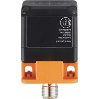
IM5184 - Inductive sensor IFM - Free user manual and instructions
Find the device manual for free IM5184 IFM in PDF.


User questions about IM5184 IFM
0 question about this device. Answer the ones you know or ask your own.
Ask a new question about this device
Download the instructions for your Inductive sensor in PDF format for free! Find your manual IM5184 - IFM and take your electronic device back in hand. On this page are published all the documents necessary for the use of your device. IM5184 by IFM.
USER MANUAL IM5184 IFM
Operating instructions
Inductive sensors with IO-Link and 2 switching outputs
Contents
1 Preliminary note 3
1.1 Symbols used 3
2 Safety instructions.... 4
3 Intended use.... 5
4 Function 6
4.1 Switching function with switch point 6
4.2 Switching function with counter 8
5 Installation.... 9
5.1 Information on flush and non-flush mounting in metal 9
5.2 Minimum distance when installing units of the same type 9
6 Electrical connection.... 11
7 Parameter setting 12
7.1 Input configuration 12
7.1.1 Configure digital input 13
7.2 Output configuration 13
7.2.1 Configure switching outputs 14
7.2.1.1 Switch point.... 14
7.2.2 Configure counters 16
7.2.3 Switch off output 16
7.2.4 Configure output polarity....16
7.2.5 Damping 16
7.3 Read counter values.... 17
7.4 Reset counters 17
7.4.1 Reset counters via IO-Link 17
7.4.2 Reset counters via input signal 17
7.5 Device reset 17
7.6 Diagnosis 18
7.6.1 Operating hours counter 18
7.6.2 Internal temperature 18
7.7 Identification 18
7.7.1 Device information 18
7.7.2 Optical localisation 18
7.7.2.1 Optical localisation via IO-Link 19
7.7.2.2 Optical localisation via input signal 19
8 Maintenance, repair and disposal 20
9 Factory setting 21
1 Preliminary note
You will find instructions, technical data, approvals and further information using the QR code on the unit / packaging or at www.ifm.com.
1.1 Symbols used
√ Requirement
Instructions
Reaction, result
[...] Designation of keys, buttons or indications
→ Cross-reference

Important note
Non-compliance may result in malfunction or interference.

Information
Supplementary note
2 Safety instructions
- The unit described is a subcomponent for integration into a system.
- The system architect is responsible for the safety of the system.
-
The system architect undertakes to perform a risk assessment and to create documentation in accordance with legal and normative requirements to be provided to the operator and user of the system. This documentation must contain all necessary information and safety instructions for the operator, the user and, if applicable, for any service personnel authorised by the architect of the system.
-
Read this document before setting up the product and keep it during the entire service life.
- The product must be suitable for the corresponding applications and environmental conditions without any restrictions.
- Only use the product for its intended purpose (→ Intended use).
- If the operating instructions or the technical data are not adhered to, personal injury and/or damage to property may occur.
- The manufacturer assumes no liability or warranty for any consequences caused by tampering with the product or incorrect use by the operator.
- Installation, electrical connection, set-up, operation and maintenance of the product must be carried out by qualified personnel authorised by the machine operator.
- Protect units and cables against damage.
3 Intended use
The unit detects metal without contact and signals this by means of a switching signal.
In addition, the unit provides a linearised distance value with a resolution of 12 bits via the IO-Link interface.
4 Function
The sensor has 2 outputs, OUT1 and OUT2, of which OUT2 can be used as a digital input. This offers the following functionalities, for example, depending on the application:
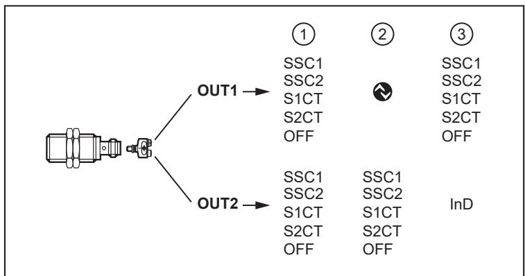
Fig. 1: function
- OUT1 and OUT2 are both used as switching outputs.
- OUT1 is used as an IO-Link interface and OUT2 as a switching output.
- OUT1 is used as a switching output and OUT2 as a digital input for an external signal. See Input configuration ( → ☐ 12).
Both outputs can also be deactivated.

The switching signal channels SSC1 and SSC2 as well as the counters S1CT and S2CT can be set separately.
Using the parameter setting software, the switching signal channels and counters can be freely assigned to the outputs OUT1 and OUT2.
4.1 Switching function with switch point
A switching signal can be provided for process value monitoring. OUTx will change its switching status according to the parameter settings as a function of the distance to the object.
You can choose between the following switch point modes according to the IO-Link smart sensor profile:
- Single point mode
- Two point mode
- Window mode
| Term | Explanation |
| H | Hysteresis, can be set via the parameter [HY] |
| High active | Switch-point logic:switching output is switched on object detection = NO (normally open) |
| Low active | Switch-point logic:switching output is not switched on object detection = NC (normally closed) |
| PDV (Process data variable) | Process data value |
| SP | Switch point (SP1 must be greater than SP2) |
| SSC (Switching Signal Channel) | Switching signal channel |
| SSC1 | Switching signal channel 1 (output signal, either via OUT1 or OUT2) |
| SSC2 | Switching signal channel 2 (output signal, either via OUT1 or OUT2) |
| Single point mode | Single switch point mode |
| Two point mode | Two switch point mode |
| Window mode | Window mode |
Tab. 1: definition of terms
Single point mode
Only one switch point (SP1) is manually set or taught. The switch-off point results from the switch point and the set hysteresis (H).

Single point mode – low active
SP1+H: switch-on point
SP1: switch-off point
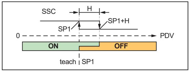
Single point mode – high active
SP1: switch-on point
SP1+H: switch-off point
Two point mode
A switch point (SP1) and a switch-off point (SP2) are manually set or taught.
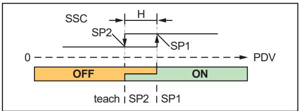
Two point mode – low active
SP2: switch-off point
SP1: switch-on point
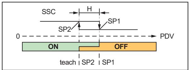
Two point mode – high active
SP1: switch-off point
SP2: switch-on point
Window mode
Two switch points (SP1) and (SP2) are manually set or taught. The two switch points delimit a window area.

Window mode – low active
- The output switches off (low active) within the switching limits SP1 and SP2.
- The output switches on (high active) when the process value leaves the window area and the set hysteresis is exceeded: SP1+H or SP2-H.
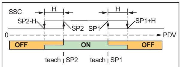
Window mode – high active
- The output switches on (high active) within the switching limits SP1 and SP2.
- The output switches off (low active) when the process value leaves the window area and the set hysteresis is exceeded: SP1+H or SP2-H.
See also: Configure switching outputs ( → ☐ 14).
4.2 Switching function with counter
The unit saves the number of switching cycles at both switching signal channels SSC1 and SSC2 using the switching cycles counters S1CT and S2CT.
The counter value can be read via the IO-Link interface.

The counter saves the switching cycles every 5 minutes. Switching cycles since the last save operation are lost in case of a voltage interruption.
When a set switching cycle threshold is reached, the switching status changes, and when the IO-Link interface is used, a data bit is set. The status change is valid for a defined hold time.
See also: Configure counters ( → 16).
The counter can be reset via an IO-Link command or a trigger edge at the digital input, or it is reset automatically when the switching cycle threshold is reached.
See also: Reset counters ( → 17).
5 Installation
5.1 Information on flush and non-flush mounting in metal

Fig. 2: cylindrical design, flush

Fig. 3: cylindrical design, non-flush
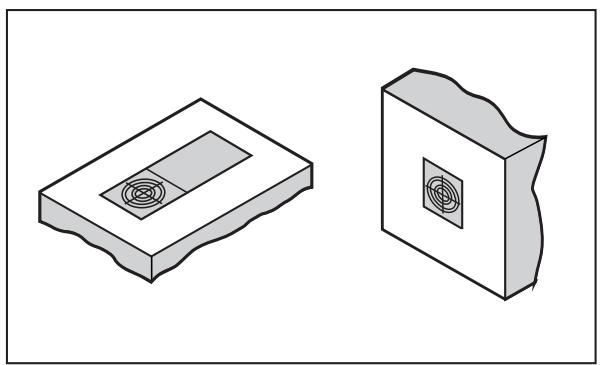
Fig. 4: rectangular design, flush

Fig. 5: rectangular design, non-flush
5.2 Minimum distance when installing units of the same type

Fig. 6: distance, flush

Fig. 7: distance, non-flush

Fig. 8: distance, frontal
The minimum distance between units may only be disregarded for units with different oscillator frequencies or different sensing principles.
6 Electrical connection

The unit must be connected by a qualified electrician.
▶ Observe the national and international regulations for the installation of electrical equipment.
▶ Disconnect power.
▶ Connect the unit as follows:


BK: black
BN: brown
BU: blue
WH: white
| Pin | Connection |
| 1 | L+ |
| 3 | L- |
| 4 | Switching output OUT1IO-LinkOFF |
| 2 | Switching output OUT2 Can be set to digital inputOFF |


Fig. 9: example connection PNP/NPN
7 Parameter setting
The parameters are set via the IO-Link interface on pin 4 using the parameter setting software.
In addition, when using pin 2 as a digital input, the following settings can also be triggered via an input signal:
- switch point teach
- reset of switching cycles counters
• optical localisation of the sensor via a flashing LED - configure switching signal channel for OUT1 / switch-point logic
See also: Input configuration ( → ☐ 12).
Parameters can be set before installation or during operation.

If you change parameters during operation, this will influence the function of the plant.
▶ Ensure that there will be no malfunctions in your plant.
During parameter setting the unit remains in the operating mode. It continues to monitor with the existing parameter until the parameter setting has been completed.
Requirements for parameter setting via the IO-Link interface:
√ A suitable parameter setting software, e.g. ifm moneo|configure
√ The Input Output Device Description (IODD) for the device, see documentation.ifm.com
√ One IO-Link master
▶ Connect the IO-Link master to a parameter setting software.
▶ Set the port of the master to the IO-Link operating mode.
▶ Connect the device to a free port of the IO-Link master.
▷ The unit switches to IO-Link mode.
▶ Change parameter settings in the software.
▶ Write parameter settings to the unit.

Notes on parameter setting → Manual of the parameter setting software
7.1 Input configuration
The digital input enables the sensor to be controlled without an IO-Link master.
OUT2 is set as a digital input via the parameter setting software. The input signal can be provided through a trigger edge (e.g. pushbutton) or a static high/low signal (e.g. switch). The input signal changes the current function and operating principle of the sensor.
Via the input configuration, the conditions for the input signal and the sensor function to be triggered can be set using the parameters [DIn2] and [DIF2].
Selectable values:
Pulse through trigger edge:
| [DIn2] | [DIF2] | Sensor function | |
| +EDG: rising trigger edge-EDG: falling trigger edge | D_IN_DEFAULT_IDLE | Factory setting: no function | |
| D_IN_BLINK_TOGGLE | Optical localisation | ||
| D_IN_TEACH_SP1 | Teach switch point 1 | For the taught switch point, the set switch point mode, switch-point logic and hysteresis values apply. | |
| D_IN_TEACH_SP2 | Teach switch point 2 | ||
| D_IN_RESET_CNT_ALL | Reset switching cycles counters 1 and 2 | ||
| D_IN_RESET_CNT_SSC1 | Reset switching cycles counter 1 | ||
| D_IN_RESET_CNT_SSC2 | Reset switching cycles counter 2 | ||
Pulse through static signal:
| [DIn2] | [DIF2] | Sensor function | |
| LEVL:static signal(0: low; 1: high) | D_IN_DEFAULT_IDLE | Factory setting: no function | |
| D_IN_OU1_HI_SSC1_LO_SSC2 | Configuration of the switching channel selection of OUT1: | ||
| Input signal (OUT2): | [ou1]: | ||
| high | SSC1 | ||
| low | SSC2 | ||
| D_IN_SSC1_HI_CLOSER_LO_OPENER | Configuration of the switch-point logic of SSC1: | ||
| Input signal (OUT2): | [SSC1 Config. Logic]: | ||
| high | high active (NO) | ||
| low | low active (NC) | ||
| D_IN_SSC2_HI_CLOSER_LO_OPENER | Configuration of the switch-point logic of SSC2: | ||
| Input signal (OUT2): | [SSC2 Config. Logic]: | ||
| high | high active (NO) | ||
| low | low active (NC) | ||
7.1.1 Configure digital input
▶ Call up [Parameters] > [Output Configuration].
▶ Select [ou2] and set digital input: [In. D].
▶ Select [Parameters] > [Digital input 2].
▶ Select [DIn2] and configure input signal: [+EDG], [-EDG], [LEVL].
▶ Select [DIF2] and set the sensor function.
7.2 Output configuration
The following functions can be selected for the switching outputs OUT1 and OUT2:
- Switching function with switch point
- Switching function with counter
• Output switched off.
The output signal at OUT1 and OUT2 can be deactivated. The output then goes to high impedance. Communication via the IO-Link interface on OUT1 remains active.
7.2.1 Configure switching outputs
See also: Switching function with switch point ( → ☐ 6).
The switching signal channels SSC1 and SSC2 can be freely assigned to the switching outputs OUT1 and OUT2.
The following parameters can be set for both switching signal channels:
| Parameter | Explanation |
| Switch point mode[SSC1 Config. Mode][SSC2 Config. Mode] | Single point Two point Window |
| Switch-point logic[SSC1 Config. Logic][SSC2 Config. Logic] | High active: switching output is switched on object detection = NO (normally open)Low active: switching output is not switched on object detection = NC (normally closed) |
| Hysteresis[SSC1 Config. Hyst][SSC2 Config. Hyst] | Single point mode: The switch-off point results from the set hysteresis. Two point mode: no function Window mode: The hysteresis setting affects the set switching limits. The hysteresis is set in % of the switch point. |
| Switch point[SSC1 Param. SP1][SSC1 Param. SP2][SSC2 Param. SP1][SSC2 Param. SP2] | SP1 (single point mode / two point mode / window mode)SP2 (two point mode / window mode) |
| Switch-on delay[SSC1 Switch-On delay][SSC2 Switch-On delay] | Adjustable switch-on delay time of the output in ms |
| Switch-off delay[SSC1 Switch-Off delay][SSC2 Switch-Off delay] | Adjustable switch-off delay time of the output in ms |
Tab. 2: switching channel setting options
Parameter setting:
▶ Call up [Parameters] > [Output Configuration].
▶ Select [ou1] and set the switching signal channel: [SSC1] or [SSC2].
▶ Select [ou2] and set the switching signal channel: [SSC1] or [SSC2].
▶ Call up [Parameters] > [Digital Output x].
▶ Select [SSCx Config. Mode] and set the switch point mode for the switching signal channel SSCx.
▶ Select [SSCx Config. Logic] and set the switch-point logic for the switching signal channel SSCx.
▶ Select [SSCx Config. Hyst] and set the hysteresis for the switching signal channel SSCx.
▶ Select [SSCx Switch-On delay] and set the switch-on delay for the switching signal channel SSCx.
▶ Select [SSCx Switch-Off delay] and set the switch-off delay for the switching signal channel SSCx.
▶ Configure the switch point: Switch point ( → ☐ 14).
7.2.1.1 Switch point
The switch point can be permanently set or taught via IO-Link or it can be taught via an external input signal.
The unit performs a check for all the setting types mentioned to ensure that the following criteria are met:
- SP1 ≤ 3800
- SP1+H ≤ 4066
• SP2 ≥ 388 and SP2 ≤ SP1-H min
(Hmin = minimum hysteresis = 3% of the set switch point)
If the criteria are not met, the current parameter settings are retained.
Set switch point via IO-Link
√ The switch point mode, the switch-point logic and the hysteresis are set.
▶ Select [Parameters] > [Digital output x].
▶ Select [SSCx Param. SP1] and set switch point 1 for the switching signal channel SSCx.
Additionally for two point mode and window mode: Select [SSCx Param. SP2] and set switch point 2 for the switching signal channel SSCx.
▶ Select [SSCx Param. SP2] and set switch point 2 for the switching signal channel SSCx.

SP1 should be as high as possible in order to be able to set SP2 and H in as wide a range as possible.
Teach switch point via IO-Link
√ The switch point mode, the switch-point logic and the hysteresis are set.
▶ Place object in position 1 in front of the sensor.
▶ Select [Parameters] > [Teach].
▶ Select [TI Select] and determine switching signal channel: [SSC1] or [SSC2].
▶ Save parameter set.
▶ Execute command: [Teach SP1].
▷ Switch point SP1 for SSCx is set.
Additionally for two point mode and window mode: Select [SSCx Param. SP2] and set switch point 2 for the switching signal channel SSCx.
▶ Place object in position 2 in front of the sensor.
▶ Execute command: [Teach SP2].
▷ Switch point SP2 for SSCx is set.
Teach switch point via input signal
√ The switch point mode, the switch-point logic and the hysteresis are set.
√ The digital input is configured with the following setting: [D_IN_TEACH_SP1]. (→ Configure digital input ☐ 13)
▶ Place object in position 1 in front of the sensor.
▶ Select [Parameters] > [Teach].
▶ Select [TI Select] and determine switching signal channel: [SSC1] or [SSC2].
▶ Trigger input signal.
▷ Switch point SP1 for SSCx is set.
Additionally for two point mode and window mode: Select [SSCx Param. SP2] and set switch point 2 for the switching signal channel SSCx.
√ The digital input is configured with the following setting: [D_IN_TEACH_SP2].
▶ Place object in position 2 in front of the sensor.
▶ Trigger input signal.
▷ Switch point SP2 for SSCx is set.
7.2.2 Configure counters
See also: Switching function with counter ( → ☐ 8).
The counters S1CT and S2CT can be freely assigned to the outputs OUT1 and OUT2.
The following parameters can be set for both counters:
| Parameter | Explanation | |
| SSC-EnhCtr_HoldTime. SSC1SSC-EnhCtr_HoldTime. SSC2 | Hold time: duration of the changed switching status when reaching the switching cycle threshold in milliseconds. Requirement: SSC-EnhCtr_AutoReload. SSCx = On. | |
| SSC-EnhCtr_AutoReload. SSC1SSC-EnhCtr_AutoReload. SSC2 | Counter reset:OFF: The output switches when the switching cycle threshold is reached. The counter continues counting until it is reset: See (→ Reset counters 17). On: The output switches when the switching cycle threshold is reached. The switching status remains active for the set hold time (→ SSC-EnhCrt_HoldTime. SSCx). Afterwards, the switching output and the counter are reset. The counter starts again at 0. | |
| SSC-EnhCtr_Count Condition. SSC1SSC-EnhCtr_Count Condition. SSC2 | Count condition: | |
| Rising: | The counter only adds up switching cycles when changing from low to high (0 → 1). | |
| Falling: | The counter only adds up switching cycles when changing from high to low (1 → 0). | |
| Both: | The counter adds up the switching cycles on both edges. | |
| ▶ Observe switching logic, see (→ Configure switching outputs 14). | ||
| SSC EnhCtr Threshold. SSC1SSC EnhCtr Threshold. SSC2 | Switching cycle threshold: Number of switching cycles at counter SxCT at which a switching signal is triggered. | |
Tab. 3: counter setting options
Parameter setting:
▶ Call up [Parameters] > [Output Configuration].
▶ Select [ou1] and set counter: [S1CT] or [S2CT].
▶ Select [ou2] and set counter: [S1CT] or [S2CT].
▶ Select [Parameters] > [Counter configuration].
▶ Select [SSC-EnhCtr_HoldTime. SSCx] and set hold time.
▶ Select [SSC-EnhCtr_AutoReload. SSCx] and set counter reset.
▶ Select [SSC-EnhCtr_Count
Condition. SSCx] and set count condition.
▶ Select [SSC EnhCtr Threshold. SSCx] and set switching cycle threshold.
7.2.3 Switch off output
▶ Call up [Parameters] > [Output Configuration].
▶ Select [oux] and set [OFF].
7.2.4 Configure output polarity
▶ Call up [Parameters] > [Output Configuration].
▶ Select [P-n] and set [PnP] or [nPn].
7.2.5 Damping
▶ Call up [Parameters] > [Damping].
▶ Select [dAP] and set a damping time in ms.

The damping time affects both outputs and the IO-Link transmission.
7.3 Read counter values
▶ Select [Parameters] > [Counter configuration].
▶ Select [SSC-EnhCtr. SSC1] and read the current counter value for SSC1.
▶ Select [SSC-EnhCtr. SSC2] and read the current counter value for SSC2.
7.4 Reset counters
7.4.1 Reset counters via IO-Link
Reset both counters:
▶ Select [Parameters] > [Counter configuration].
▶ Execute command: [Reset counter to zero].
▷ Both switching cycles counters are set to 0.
Reset counters individually:
▶ Select [Parameters] > [Setup].
▶ Execute command: [Reset SSC1 Counter].
▷ The switching cycles counter SSC1 is set to 0.
▶ Execute command: [Reset SSC2 Counter].
▷ The switching cycles counter SSC2 is set to 0.
7.4.2 Reset counters via input signal
√ The digital input is configured with the following setting: [D_IN_RESET_xxx]. (→ Configure digital input ☐ 13)
▶ Trigger input signal.
▷ Counter is reset:
- Both counters when setting: [D_IN_RESET_ALL]
- Switching cycles counter SSC1 when setting: [D_IN_RESET_SSC1]
- Switching cycles counter SSC2 when setting: [D_IN_RESET_SSC2]
7.5 Device reset
The unit can be reset to factory settings.

We recommend documenting your own settings in the chapter Factory setting before carrying out a reset.
▶ Select [Parameters] > [Setup].
▶ Execute command: [Restore Factory Settings].
▷ The unit carries out a reboot.
7.6 Diagnosis
7.6.1 Operating hours counter
The operating hours since the first set-up are stored by the unit.
The current value can be read via the IO-Link interface.
▶ Select [Parameters] > [Diagnosis].
▶ Select [Operating hours] and read value.
7.6.2 Internal temperature
The sensor measures the internal temperature.
The current value can be read via the IO-Link interface.
▶ Select [Parameters] > [Diagnosis] > [Temperature].
▶ Select [Internal temperature] and read value.
7.7 Identification
7.7.1 Device information
Unalterable device information is stored on the unit. This includes:
- Product name
- Product family
- Manufacturer
• Manufacturer ID - Device ID
- Serial number
- Description
• Hardware / firmware revision
In addition, further freely definable tags with a maximum length of 32 characters can be assigned to the unit via the IO-Link interface using suitable parameter setting software. This includes:
• application-specific tag
- function tag
- location tag
Read/edit device information:
▶ Select [Identification].
▶ Read device information or edit editable parameters.
7.7.2 Optical localisation
The sensor can be located remotely in the system via the IO-Link interface.
When using the command, the switching status LED flashes.
7.7.2.1 Optical localisation via IO-Link
▶ Select [Identification].
▶ Execute command: [Flash On].
▶ To end the flashing process: Execute command: [Flash Off].
7.7.2.2 Optical localisation via input signal
√ The digital input is configured with the following setting: [D_IN_BLINK_TOGGLE]. (→ Configure digital input ☐ 13)
▶ Trigger input signal.
8 Maintenance, repair and disposal
The operation of the unit is maintenance-free.
Only the manufacturer is allowed to repair the unit.
▶ After use dispose of the device in an environmentally friendly way in accordance with the applicable national regulations.
9 Factory setting
| Parameter | Factory setting | User setting | |
| ou1 | SSC1 | ||
| ou2 | SSC2 | ||
| P-n | PnP | ||
| dAP | 0 ms | ||
| SSC1 | SSC1 Param. SP1 | 3800 | |
| SSC1 Param. SP2 | 388 | ||
| SSC1 Config. Logic | High active | ||
| SSC1 Config. Mode | Single point | ||
| SSC1 Config. Hyst | 7% | ||
| SSC1 Switch-On delay | 0 ms | ||
| SSC1 Switch-Off delay | 0 ms | ||
| SSC2 | SSC2 Param. SP1 | 3800 | |
| SSC2 Param. SP2 | 388 | ||
| SSC2 Config. Logic | Low active | ||
| SSC2 Config. Mode | Single point | ||
| SSC2 Config. Hyst | 7% | ||
| SSC2 Switch-On delay | 0 ms | ||
| SSC2 Switch-Off delay | 0 ms | ||
| S1CT | SSC-EnhCtr_HoldTime. SSC1 | 100 ms | |
| SSC-EnhCtr_AutoReload. SSC1 | On | ||
| SSC-EnhCtr_Count Condition. SSC1 | Rising | ||
| SSC EnhCtr Threshold. SSC1 | 100 | ||
| S2CT | SSC-EnhCtr_HoldTime. SSC2 | 100 ms | |
| SSC-EnhCtr_AutoReload. SSC2 | On | ||
| SSC-EnhCtr_Count Condition. SSC2 | Falling | ||
| SSC EnhCtr Threshold. SSC2 | 100 |

- 1 PRELIMINARY NOTE
- 1.1 SYMBOLS USED
- 2 SAFETY INSTRUCTIONS
- 3 INTENDED USE
- 4 FUNCTION
- 4.1 SWITCHING FUNCTION WITH SWITCH POINT
- 4.2 SWITCHING FUNCTION WITH COUNTER
- 5 INSTALLATION
- 5.1 INFORMATION ON FLUSH AND NON-FLUSH MOUNTING IN METAL
- 5.2 MINIMUM DISTANCE WHEN INSTALLING UNITS OF THE SAME TYPE
- 6 ELECTRICAL CONNECTION
- 7 PARAMETER SETTING
- 7.1 INPUT CONFIGURATION
- 7.1.1 CONFIGURE DIGITAL INPUT
- 7.2 OUTPUT CONFIGURATION
- 7.2.1 CONFIGURE SWITCHING OUTPUTS
- 7.2.1.1 SWITCH POINT
- 7.2.2 CONFIGURE COUNTERS
- 7.2.3 SWITCH OFF OUTPUT
- 7.2.4 CONFIGURE OUTPUT POLARITY
- 7.2.5 DAMPING
- 7.3 READ COUNTER VALUES
- 7.4 RESET COUNTERS
- 7.4.1 RESET COUNTERS VIA IO-LINK
- 7.4.2 RESET COUNTERS VIA INPUT SIGNAL
- 7.5 DEVICE RESET
- 7.6 DIAGNOSIS
- 7.6.1 OPERATING HOURS COUNTER
- 7.6.2 INTERNAL TEMPERATURE
- 7.7 IDENTIFICATION
- 7.7.1 DEVICE INFORMATION
- 7.7.2 OPTICAL LOCALISATION
- 7.7.2.1 OPTICAL LOCALISATION VIA IO-LINK
- 7.7.2.2 OPTICAL LOCALISATION VIA INPUT SIGNAL
- 8 MAINTENANCE, REPAIR AND DISPOSAL
- 9 FACTORY SETTING
Brand : IFM
Model : IM5184
Category : Inductive sensor