
OJ5085 - Motion detector IFM - Free user manual and instructions
Find the device manual for free OJ5085 IFM in PDF.

| Product type | Motion sensor (retro-reflective photocell) |
| Model | OJ5085 |
| Brand | IFM |
| Series | efector200® / OJ51xx |
| Power supply | 10-30 V DC (PNP or NPN depending on wiring) |
| Connection | 3 wires: BN (L+), WH (output/programming), BU (L-) |
| Main functions | Non-contact detection of transparent objects, programmable NC/NO output, sensitivity adjustment (static and moving), electronic lock |
| Range | See label (e.g., 50 mm on honeycomb reflector 50x50 mm E20722) |
| LED indicators | Green (power on), Yellow (output active), Red (error), Yellow+Red flashing (short circuit or internal error) |
| Programming | By push button or programming wire (pin 2/WH) |
| Mounting | Mounting clip supplied, aim light spot at reflector |
| Recommended reflector | Honeycomb reflector (e.g., E20722) or reflex adhesive tape |
| Maintenance | Clean lenses regularly |
| Safety | Disconnect power before connection |
| Protection | Short circuit and polarity reversal (implicit) |
Frequently Asked Questions - OJ5085 IFM
User questions about OJ5085 IFM
0 question about this device. Answer the ones you know or ask your own.
Ask a new question about this device
Download the instructions for your Motion detector in PDF format for free! Find your manual OJ5085 - IFM and take your electronic device back in hand. On this page are published all the documents necessary for the use of your device. OJ5085 by IFM.
USER MANUAL OJ5085 IFM
natural_image
Technical line drawing of two vertical panels with circular components and a base, no text or symbols presentnatural_image
Technical diagram showing a mechanical assembly with three circular components and two cylindrical parts, no text or symbols present.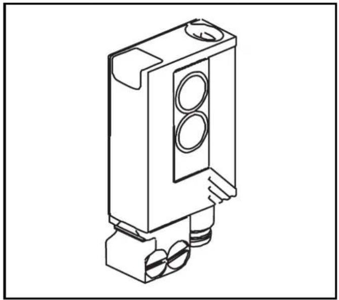
natural_image
Technical line drawing of a mechanical component with three circular ports and mounting base (no text or symbols)natural_image
Technical line drawing of a screwdriver holding a rectangular device with three circular ports (no text or symbols)
natural_image
Technical diagram of a mechanical assembly with arrows indicating motion or force direction (no text or symbols)Function and features
In conjunction with a prismatic reflector or reflective tape the retro-reflective sensor detects transparent objects and materials without contact and indicates their presence by a switched signal.
Range (r): see type label (value referred to prismatic reflector with 50x50 mm, E20722).
Electrical connection
Isolate power, then connect the unit (see page 22 or type label).
Programming of the output function by push button or programming wire (see page 14).
Installation
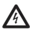
* In the following sections installation and set-up are described using the example of the type with front lens. The functions of the units with side lens are identical.
Fix prismatic reflector / reflective tape in desired position. Align the photocell photocell towards the reflector and fasten it with a mounting fixture (see the next page for installation); the light spot must hit the prismatic reflector.
Mounting of the series OJ51xx
The units of the OJ51xx series have two fixing holes on the side for mounting. A mounting fixture is not supplied.
Maximum range is only possible with precise alignment.
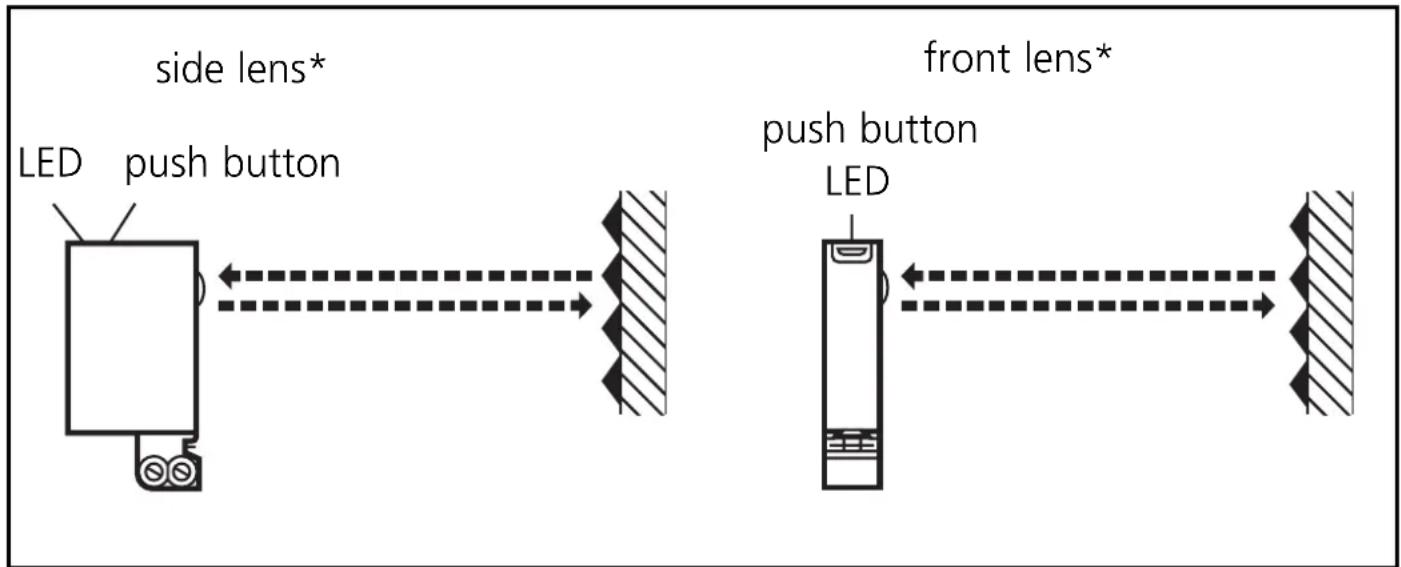
Installation of the supplied mounting fixture
natural_image
Technical diagram showing assembly of a mechanical component with two cylindrical parts and a housing, no text or symbols present.
natural_image
Technical line drawing of a mechanical component with three circular ports and mounting base (no text or symbols)Secure the mounting fixture with the screws supplied, then slide the unit into the slot of the fixture until the spring clicks home.
natural_image
Technical line drawing of a screwdriver holding a rectangular device with three circular ports (no text or symbols)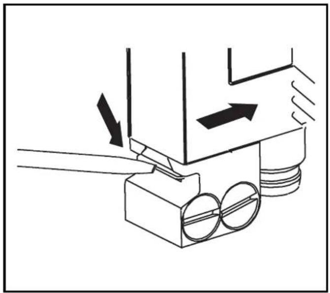
natural_image
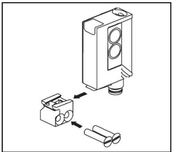
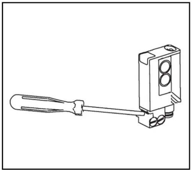
Technical diagram of a mechanical assembly with arrows indicating motion or force direction (no text or symbols)To remove the unit press the spring down with a screwdriver and slide the unit out.
NB: Commissioning
Without any further settings the retro-reflective sensor is set to the max. range. This means that for the detection of transparent objects the retro-reflective sensor must be set to the optimum excess gain according to the settings described below.
Setting of the sensitivity with stationary objects\*
| 1 | Activate the programming mode of the unit.Press for about 2suntil the red LED flashes. ← ← |
| The red LED goes out; the yellow and green LEDs flash alternately.The unit is in the programming mode. |
| 2 | Set the sensitivitywithobject. | ||||
| Press once. | 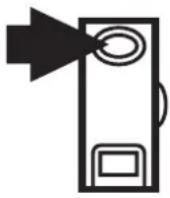 | → |  |  | |
| The yellow and green LEDs go out for approx. 1s,then flash again alternately. | |||||
| 3 | Set the sensitivitywithoutobject.Press once.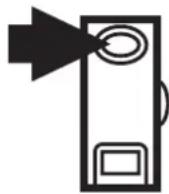 ←→ ←→  |
| The yellow and green LEDs go out for approx. 1s,after approx 3s the green LED is on.The unit is in the operating mode. |
You can also proceed in reverse order: first setting without the object, then with the object.
* The sensitivity can also be set in exactly the same way using the programming wire (pin 2 / WH). To activate the functions the programming wire is connected for the appropriate time to L+ (pin 1 / BN) for PNP units or to L- (pin 3 / BU) for NPN units. Feedback: If setting was not successful via the programming wire, the output will switch for 2s. The unit then reverts to the operating mode with the sensitivity unchanged.

If the setting of the sensitivity is not possible (e.g. object signal and background signal are about the same), the red LED flashes after step 3 for approx. 2s. The unit then passes into the operating mode with the sensitivity being unchanged.
If the setting button is not activated for 15 minutes during the programming process, the unit passes automatically into the operating mode with the sensitivity being unchanged.
Setting of the sensitivity with moving objects*
| 1 | Activate the programming mode of the unit.Press for about 2s untilthe red LED flashes.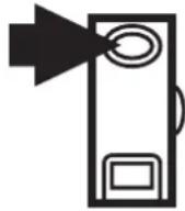 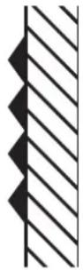 |
| The red LED goes out; the yellow and green LEDs flash alternately.The unit is in the programming mode. |
* The sensitivity can also be set in exactly the same way using the programming wire (pin 2 / WH). To activate the functions the programming wire is connected for the appropriate time to L+ (pin 1 / BN) for PNP units or to L- (pin 3 / BU) for NPN units. Feedback: If setting was not successful via the programming wire, the output will switch for 2s. The unit then reverts to the operating mode with the sensitivity unchanged.
| 2 | Allow objects to pass through the detection area during the measurement (about 1s) (number of the objects between min. 8Hz and max. switching frequency).Press once.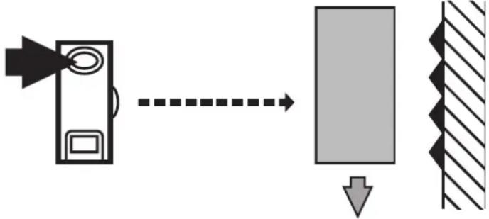 |
| The yellow and green LEDs go out for approx. 1s, then flash again alternately. | |
| 3 | Allow objects to pass through the detection area during the measurement (about 1s) (number of the objects between min. 8Hz and max. switching frequency).Press once. |
| The yellow and green LEDs go out for approx. 1s, after approx. 3s the green LED is on.The unit is in the operating mode. |

If the setting of the sensitivity is not possible (e.g. object signal and background signal are about the same), the red LED flashes after step 3 for approx. 2s. The unit then passes into the operating mode with the sensitivity being unchanged.
If the setting button is not activated for 15 minutes during the programming process, the unit passes automatically into the operating mode with the sensitivity being unchanged.
Additional setting procedure to prismatic reflector\*
Should it not be possible to program the unit with the settings described above, the sensitivity can be set to the prismatic reflector. In this case, however, the excess gain to the object to be detected is reduced.
- Go into the programming mode (see step 1).
- Align the unit in such a way that the prismatic reflector is hit.
- Press the push button twice (see steps 2 and 3).
* The sensitivity can also be set in exactly the same way using the programming wire (pin 2 / WH). To activate the functions the programming wire is connected for the appropriate time to L+ (pin 1 / BN) for PNP units or to L- (pin 3 / BU) for NPN units.

The setting of the sensitivity to the prismatic reflector is possible in any case.
Setting of the maximum sensitivity\*
- Go into the programming mode (step 1).
- Align the unit so that no light is reflected.
- Press the setting button twice (see steps 2 and 3).
* The maximum sensitivity can also be set in exactly the same way using the programming wire (pin 2 / WH). To activate the functions the programming wire is connected for the appropriate time to L+ (pin 1 / BN) for PNP units or to L- (pin 3 / BU) for NPN units.
Electronic lock
Activate the lock by connecting the programming wire for about 15s – 20s*.
De-activate the lock by connecting the programming wire again for 15s - 20s*.
* To activate the functions the programming wire (pin 2 / WH) is connected to L+ (pin 1 / BN) for PNP units or to L- (pin 3 / BU) for NPN units for the appropriate time.
Programming the output function\*
Press for 10s. 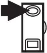 | → | The red LED starts to flash fast after 2s. Then the yellow and green LEDs flash alternately. After 10s all LEDs go off, the output function has changed from light-on mode to dark-on mode (or vice versa). |
* The output function can be programmed in exactly the same way using the programming wire (pin 2 / WH). To activate the functions the programming wire is connected for the appropriate time to L+ (pin 1 / BN) for PNP units or to L- (pin 3 / BU) for NPN units.
Operation
Check the safe functioning of the unit. Display by LEDs.
| LED green is lit Unit is ready for operation. | |
| LED yellow is lit Output is switched. | |
| LED red is lit | Error in object detection, e.g. maladjustment, soiling of the lenses. |
| LEDs yellow + red | Flash alternately, 2 Hz: output short-circuited. Flash alternately, 1 Hz: internal malfunction (output is not switched). |
Maintenance
Keep the lens of the sensor free from soiling.
natural_image
Technical diagram showing a mechanical assembly with three circular components and two cylindrical parts, no text or symbols present.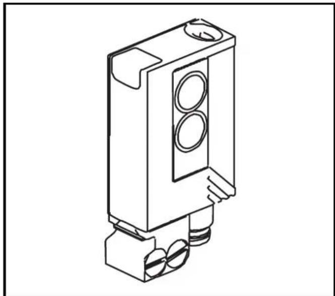
natural_image
Technical line drawing of a mechanical component with three circular ports and mounting base (no text or symbols)natural_image
Line drawing of a mechanical device with a screwdriver extending from its end (no text or symbols)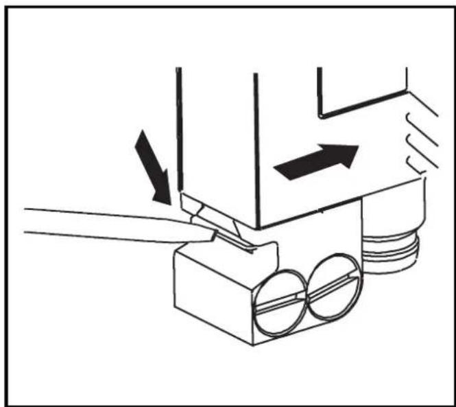
natural_image
Technical diagram of a mechanical assembly with arrows indicating motion or force direction (no text or symbols)
- Function and features
- Electrical connection
- Installation
- Installation of the supplied mounting fixture
- NB: Commissioning
- Setting of the sensitivity with stationary objects\*
- Additional setting procedure to prismatic reflector\*
- Setting of the maximum sensitivity\*
- Electronic lock
- Programming the output function\*
- Operation
- Maintenance
Brand : IFM
Model : OJ5085
Category : Motion detector