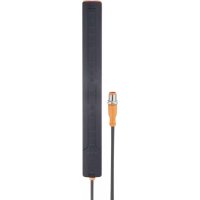
KQ1001 - Detector IFM - Free user manual and instructions
Find the device manual for free KQ1001 IFM in PDF.


User questions about KQ1001 IFM
0 question about this device. Answer the ones you know or ask your own.
Ask a new question about this device
Download the instructions for your Detector in PDF format for free! Find your manual KQ1001 - IFM and take your electronic device back in hand. On this page are published all the documents necessary for the use of your device. KQ1001 by IFM.
USER MANUAL KQ1001 IFM
Operating instructions
Capacitive level sensor
KQ10
Contents
1 Preliminary note.... 4
1.1 Symbols used.... 4
2 Safety instructions 5
3 Intended use 6
3.1 Application area 6
3.2 Restriction of the application area.... 6
4 Getting started 7
5 Function 8
5.1 Measuring principle 8
5.2 Operating modes 8
5.3 IO-Link 9
5.4 Application adjustments 9
5.5 Switching outputs.... 10
5.6 Diagnostic data 10
5.6.1 Index of level edge 11
5.6.2 Signal strength referred to the dynamic range 11
5.6.3 Filling edge sharpness.... 11
5.6.4 Installation quality.... 12
5.7 Internal temperature.... 12
5.8 Switching cycles counters 12
5.9 Operating hours counter 12
5.10 Damping function 12
5.11 Deposit detection 13
6 Installation.... 14
6.1 Installation of several devices 14
6.2 Installation on bypass pipes.... 15
6.3 Installation on the tank.... 15
6.4 Installation on exchangeable tanks 16
6.5 Notes on tank adjustment.... 16
6.6 Notes on grounding.... 17
7 Electrical connection 18
8 Operating and display elements.... 19
9 Set-up 20
9.1 Application adjustments 20
9.1.1 Empty adjustment 20
9.1.2 Full adjustment.... 20
9.1.3 Dynamic adjustment 21
9.1.4 Empty and full adjustment 21
9.2 Adjustment of the switch points 21
10 Parameter setting 22
10.1 Adjustable parameters 22
10.1.1 Sensor parameters.... 22
10.1.2 Indication parameters.... 23
10.1.3 Diagnostic parameters 23
10.1.4 Configuration of the switching outputs.... 23
10.1.5 Other parameters.... 24
10.2 Commands 24
10.2.1 Application adjustments 24
10.2.2 Setting of the switch points.... 24
10.2.3 Other commands 25
10.3 Active events and device status 25
11 Troubleshooting.... 26
11.1 Application adjustment refused.... 26
11.2 Deviation between process value and level.... 26
11.2.1 Evaluate the index of the level edge.... 27
11.2.2 Evaluate signal strength and filling edge sharpness 27
11.3 Events 27
11.3.1 Signal fault 27
11.3.2 Plausibility error.... 28
11.3.3 Maintenance required - Cleaning.... 28
12 Maintenance, repair and disposal 29
13 Factory settings.... 30
1 Preliminary note
You will find instructions, technical data, approvals, accessories and further information using the QR code on the device / packaging or at documentation.ifm.com.
1.1 Symbols used
Requirement
Instruction
Reaction, result
bold Designation of keys, buttons or indications
→ Cross-reference without link
→ Cross-reference with link

Important note
Non-compliance may result in malfunction or interference

Information
Supplementary note
2 Safety instructions
- The unit described is a subcomponent for integration into a system.
- The system architect is responsible for the safety of the system.
-
The system architect undertakes to perform a risk assessment and to create documentation in accordance with legal and normative requirements to be provided to the operator and user of the system. This documentation must contain all necessary information and safety instructions for the operator, the user and, if applicable, for any service personnel authorised by the architect of the system.
-
Read this document before setting up the product and keep it during the entire service life.
- The product must be suitable for the corresponding applications and environmental conditions without any restrictions.
- Only use the product for its intended purpose (→ Intended use).
- If the operating instructions or the technical data are not adhered to, personal injury and/or damage to property may occur.
- The manufacturer assumes no liability or warranty for any consequences caused by tampering with the product or incorrect use by the operator.
- Installation, electrical connection, set-up, operation and maintenance of the product must be carried out by qualified personnel authorised by the machine operator.
- Protect units and cables against damage.
- The unit complies with the standard EN 61000-6-4 and is a class A product. The unit may cause radio interference in domestic areas. If interference occurs, the user must take appropriate actions.
3 Intended use
3.1 Application area
The device detects metals, almost all plastics, glass, ceramics, wood, paper, oils, greases, water and all hydrous materials without contact and indicates their presence by providing a switching signal or a continuous process value from 0...100 %.
The device detects the medium through the tank wall. The wall is suppressed by means of an adjustment function, so that only the medium is detected.

The tank wall must be made of a non-metal material.

Incorrect installation or adjustment may lead to wrong process values being provided.
▶ Observe chapter Set-up ➕ 20.
▶ Check proper function by an application test.
3.2 Restriction of the application area
- Using the device in direct contact with the medium, with ionising radiation or in environments with direct condensation is not allowed.
- This is a class A product. This product may cause radio interference in domestic areas.
▶ If required, take appropriate EMC screening measures.
• In case of highly adhesive media (e.g. glue, shampoo), there may be film formation.
• Highly conductive films or foams may be detected as level.
4 Getting started
For fast set-up, carry out the following steps:
- Fix the device to the tank using adhesive tape ➕ 14.
- Connect the device to an IO-Link master ( → documentation of the IO-Link master / software used).
- Carry out empty adjustment and / or full adjustment:

Fig. 1: Empty adjustment
▶ Click on [Adjust empty tank]

Fig. 2: Full adjustment
▶ Click on [Adjust full tank]

The steps required may differ depending on the application.
Detailed description at: Set-up ➕ 20.
5 Function
5.1 Measuring principle
The device detects the level according to the capacitive measuring principle.
- An electrical field is generated and influenced by the medium to be detected. This change to the field causes a measurement signal that is electronically evaluated.
- The dielectric constant of a medium is important for its detection. For a constant wall thickness, media with a high dielectric constant (e.g. water) generate a strong measurement signal, media with a low dielectric constant (e.g. oils) a correspondingly lower signal.
- The device has 16 capacitive measuring segments (4). They generate measurement signals depending on the degree of coverage.
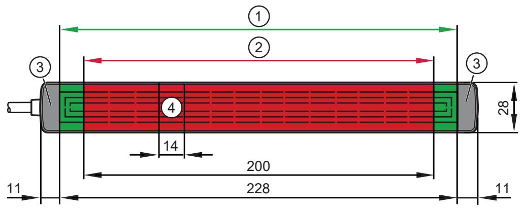
Fig. 3: Measuring range and detection range
1: Detection range (green)
2: Measuring range (red)
3: Limit range (grey)
4: Measuring segment (electrode)
Media can be detected within the detection range (1). The process value refers to this range.
The measuring range (2) is always two sensor elements smaller than the detection range. This is where accuracy is at its highest.
The limit range (3) is outside the detection range.

The device always provides the most recent valid process value. A process value is valid if the device status has the value "0".
5.2 Operating modes

The device can only be configured via IO-Link.
The following operating modes can be set:
• Measurement over the maximum detection range
- Limitation of the detection range
Adjacent sensor elements can be suppressed from the top as well as from the bottom in order to reduce the detection range → 22. A maximum of 10 sensor elements can be deactivated.
- Orientation
The evaluation logic of the device can be rotated by 180° so that the device can also be mounted overhead, with the connection cable facing upwards → 22. Note that the limitation of the sensor elements always refers to the level. Limitation from the bottom refers to the lower sensor elements and limitation from the top refers to the upper sensor elements.
- Setting of the sensor sensitivity
Two levels are available for sensor sensitivity, high and low ➕ 22. The high sensitivity level is suited for the detection of low dielectric bulk material, for example. The low sensitivity level can be used for detection of high dielectric media.
5.3 IO-Link
IO-Link is a communication system for connecting intelligent sensors and actuators to automation systems. IO-Link is standardised in the IEC 61131-9 standard.

General information on IO-Link at io-link.ifm

Input Output Device Description (IODD) with all parameters, process data and detailed descriptions of the device at documentation.ifm.com
IO-Link offers the following advantages:
• Interference-free transmission of all data and process values
• Parameter setting in the running process or presetting outside the application
- Parameters for identifying the connected devices in the system
• Additional parameters and diagnostic functions
• Automatic backup and restore of parameter sets in case of device replacement (data storage)
- Logging of parameter sets, process values and events
• Device description file (IODD - Input Output Device Description) for easy project planning
• Standardised electrical connection
- Remote maintenance
5.4 Application adjustments
Before the device is used, it must be adjusted. Different application adjustments are available.
- Empty adjustment
After fixing the device to the tank, this adjustment is carried out to suppress the environment. No medium to be detected must be in the detection range. If only an empty teach is carried out, the device operates independently of the medium.
- Full adjustment
A full adjustment is carried out with the detection range being completely covered. The sensor is adjusted to the medium to be detected. Changing the medium without carrying out a new adjustment can have a detrimental effect on the performance of the sensor in the application.
• Dynamic adjustment
If no full adjustment or empty adjustment can be carried out, a dynamic adjustment can be carried out. The level of the medium to be detected must be in the detection range and must be at a distance of at least 4 sensor elements from the upper edge of the detection range ➕ 8.
Dynamic adjustment, similar to full adjustment, is performed to the medium. This means that changing the medium without carrying out a new adjustment can have a detrimental effect on the performance of the sensor in the application.

Only use the dynamic adjustment as sole adjustment if there is no other possibility.

If an empty adjustment and/or full adjustment has been carried out, no additional dynamic adjustment will be accepted.
The application adjustments can be combined. Sorted by operational reliability, the following combinations are possible:
| Operational reliability | Adjustment | Application example |
| 1 (highest) | Empty adjustment and full adjustment | For complex applications (e.g. draining liquid films). |
| 2 | Only empty adjustment | When the medium in the tank is changed. In case of a significantly fluctuating dielectric constant. |
| 3 | Only full adjustment | If no empty adjustment is possible. If the medium is not changed. |
| 4 (lowest) | Only dynamic adjustment | Only if no empty adjustment or full adjustment is possible. |
5.5 Switching outputs
The device has 3 physical switching outputs that can be configured differently ➕ 23.
| Description | Setting |
| Switching output only responds to events / faults | FOUx = ON or OFF OUx = Diagnostic output |
| Switching output responds to process value and possibly existing events / faults | FOUx = ON or OFF |
| Switching output only responds to process value | FOUx = OU OUx = HNO, HNC, FNO or FNC |
| Switching output neither responds to process value nor events / faults | OUx = OFF |
FOUx = ON → switching output activated in case of events / faults
FOUx = OFF → switching output deactivated in case of events / faults
The following events / faults are taken into account ➕ 25:
- Parameter missing
- Maintenance required - Cleaning
• Device hardware fault - Signal fault
- Plausibility error.
5.6 Diagnostic data
The device provides diagnostic data for the assessment of the operational reliability. Besides, root cause analysis is facilitated in case of a fault.
There are four diagnostic parameters ➕ 23:
- Index of level edge
• Signal strength referred to the dynamic range - Filling edge sharpness
• Installation quality.
5.6.1 Index of level edge
The parameter indicates the electrode at which the edge of the level was detected. In this example, the index of the level edge has the value 3.
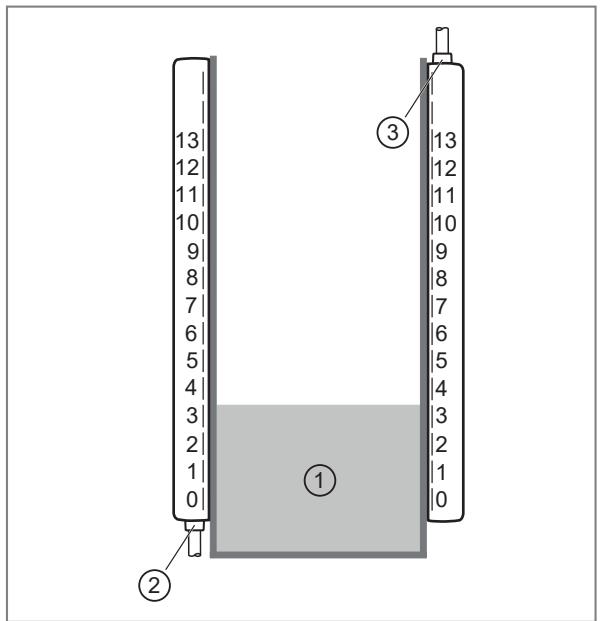
Fig. 4: Index of level edge
1: Medium
2: Orientation: lower connection
3: Orientation: upper connection
The zero electrode is always at the bottom, independent of the orientation of the device. The set limitation of sensor elements from the top or from the bottom limits the provided index. For example, if the limitation of the elements from the bottom has been set to 2, the minimum index of the level edge will also be 2.
If no level edge can be detected, the device decides whether the detection range is completely covered or uncovered based on the application adjustments carried out.
• Detection range completely covered: "13-topOffset"
- Detection range uncovered: "bottom
Offset"
If no decision can be made based on the adjustments or if no adjustment has been carried out, the substitute value "0xFF" is provided.
5.6.2 Signal strength referred to the dynamic range
Indicates the signal strength measured at the edge of the level in a value range from 0 to 100. If no edge of the level could be detected, the substitute value "0xFF" is provided. A low value can for example indicate that the wall is too thick or that the medium has a low dielectric constant.
5.6.3 Filling edge sharpness
Relates to the sharpness of the edge of the level in a value range from 0 to 100. If no edge of the level could be detected, the substitute value "0xFF" is provided. A low value can for example indicate an uneven filling edge.
High edge sharpness
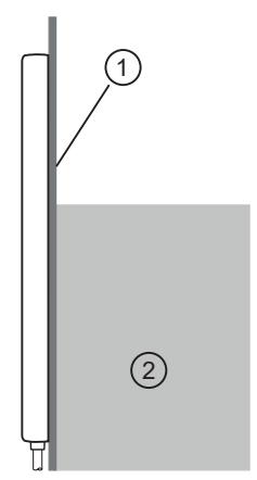
Low edge sharpness


Fig. 5: Representation of the edge sharpness
1: Tank wall
2: Medium
If the edge sharpness is too low, it may not be possible to correctly detect the level.

The edge sharpness can only be determined if the medium to be detected is within the measuring range of the device.
5.6.4 Installation quality
Relates to the installation quality in a value range of 0-100. If there is full adjustment, a value estimated by the device is provided. A low value may for example indicate metal parts that are too close to the sensing face of the device ➕ 14.
5.7 Internal temperature
The internal temperature of the device can be read ➕ 24. Minimum value and maximum value are cyclically stored in the memory of the device. The values can be used for orientation after a new start of the device.
5.8 Switching cycles counters
The number of switching cycles can be read or reset if the switching output has been configured accordingly → 25. The switching cycles counters are cyclically stored in the memory of the device. The values can be used for orientation after a new start of the device.
5.9 Operating hours counter
The number of operating hours can be read from the memory of the device via IO-Link ➞ 24.
5.10 Damping function
With the damping function, the process value can be filtered and delayed → 22.
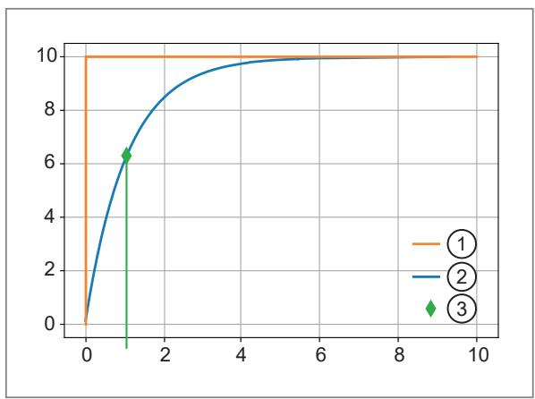
Fig. 6: Example: damping function for a damping value of one second
1: Measuring value sensor (without damping)
2: Process value / level (with damping)
3: Damping value (1 s)
5.11 Deposit detection
The device can detect deposits in the measuring range building up gradually and signals these via the event “Maintenance required - Cleaning” ➞ 28.
Requirements:
• Empty and full adjustment available ➞ 20
• Signal strength ≤ 15 ➞ 23
• The index of the level edge is in the detection range ➞ 23
For a correct function of the deposits detection the tank must be free from deposits during the adjustment. Only deposits that build up after the adjustment can be detected.
The deposits detection does not function with highly adhesive media and/or highly conductive media.
6 Installation
If the device is installed in a metal tank with a non-metal window, the following installation conditions are to be noted in order to ensure correct operation:
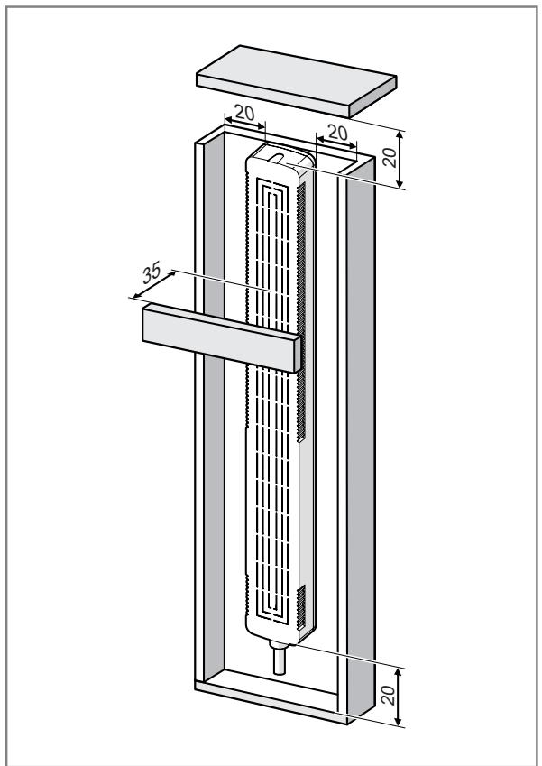
Fig. 7: Installation distances to metal objects
▶ Lay the connection cable as straight as possible and do not coil it.

If the device is installed with the cable facing upwards, the parameter Orientation must be set to top / upper connection: Sensor parameters ➕ 22.

If you do not adhere to the installation conditions, you do so at your own risk.
6.1 Installation of several devices
Several devices can be mounted head to head or so that they overlap.
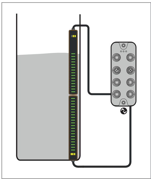
Fig. 8: Installation of several devices
Adapt the parameter Orientation according to the installation direction.
6.2 Installation on bypass pipes
Using the E12676 mounting adapter, the device can be mounted on bypass pipes with a circular cross section. To ensure correct mounting, the external diameter of the bypass pipe should be between 5 and 25 mm.
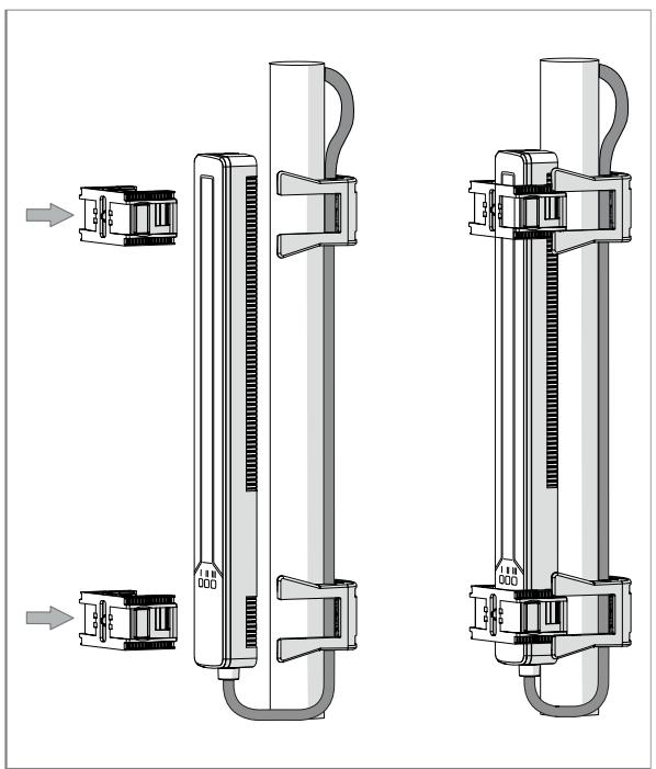
Fig. 9: Installation on bypass pipes
When the device is mounted on a bypass pipe, the supply cable must be guided through the cable clamp.
6.3 Installation on the tank
The device can be attached to tank walls by means of double-sided adhesive tape (available as accessory E12677). Using different adhesive tape may lead to the device detaching from the tank and is done at your own risk. The adhesive tape used must not contain any conductive material.
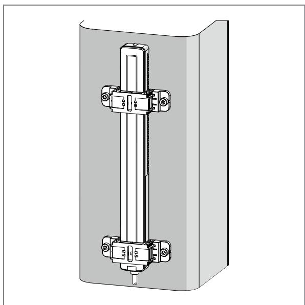
Fig. 10: Installation on the tank
The device must be flush to the tank. Curved, flexible tanks may lead to measurement errors and malfunction.
If curvature of the tank cannot be avoided, the sensor elements at the edge of the device that are affected by the curvature can be deactivated → 22.
6.4 Installation on exchangeable tanks
For exchangeable tanks, the back of the device can be screwed to the tank using the E12675 mounting adapter and an M6 screw. One screwing point per adapter.
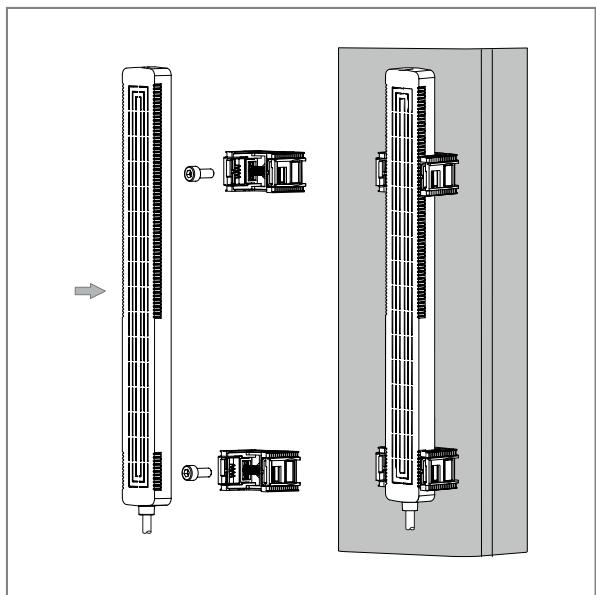
Fig. 11: Installation on exchangeable tanks
Maintain a constant distance between sensor and tank.
6.5 Notes on tank adjustment
- During set-up or after replacement of the device, a tank adjustment must be carried out.
- If only an empty adjustment has been carried out, the adjustment should be repeated when the device is removed from the tank and reinstalled.
- If no empty adjustment or no other adjustment in addition to the empty adjustment has been carried out, new adjustments should be carried out when the medium or tank is changed.
6.6 Notes on grounding

In order for the device to function correctly, sufficient grounding of the device as well as of the installation and tank must be ensured.
7 Electrical connection

The unit must be connected by a qualified electrician.
▶ Observe the national and international regulations for the installation of electrical equipment.
▶ Disconnect power.
▶ Connect the unit as follows:

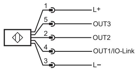
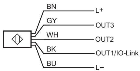
Fig. 12: Wiring diagram (colours to DIN EN60947-5-2)
BK: Black
GY: Grey
BN: Brown
WH: White
BU: Blue
| Pin | Assignment |
| 1 | L+ |
| 3 | L- |
| 4 (OUT1) | Switching signalIO-Link |
| 2 (OUT2) | Switching signal |
| 5 (OUT3) | Switching signal |
8 Operating and display elements
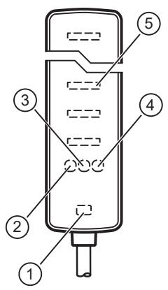
1: LED green (status indication)
2: LED yellow (switch point 1 / OUT1)
3: LED yellow (switch point 2 / OUT2)
4: LED yellow (switch point 3 / OUT3)
5: LED bar graph green (indication of the level)
Status LED (1) is on when the device is connected to the voltage supply and ready for operation.
The switch point LEDs (2), (3) and (4) are on when the corresponding output is switched. The switching outputs must be configured accordingly → 23.
The LED bar graph (5) indicates the level after the adjustment has been carried out.
If no adjustment has been carried out, this is indicated by means of a periodic running light.
If an error occurs, the LED bar graph alternates between the last valid level and the error indication:
| 4x flashing | Hardware failure |
| 3x flashing | At least one measured capacitance exceeds the maximum range. No correct adjustment could be made.orNo adjustment available, as this error prevents correct adjustment. In that case, the periodic running light is no longer displayed. |
| 2x flashing | No level can be calculated due to inconsistent data. |
| 1x flashing | Deposits recognised. |
If the error indication is active, the approximate position of the error is displayed.
If the error cannot be indicated, the 3 top and bottom LEDs light up.
Some or all of the LEDs can be deactivated via IO-Link ➕ 23.
The following LED modes can be set:
- all LEDs inactive
• only status LED active
• status and switch point LEDs active
• all LEDs active (factory setting)
9 Set-up

On delivery the device is not operational. First an application adjustment must be carried out.
After installation and electrical connection, the configuration of the device can be changed and adjustments can be carried out.

Changing one of the following parameters will reset the application adjustment → 22:
√ Limitation of sensor elements
√ Orientation
√ Sensitivity
▶ If these parameters are to deviate from the factory settings, they must be transferred to the device prior to the application adjustment.
9.1 Application adjustments

Do not touch the device during adjustment.

After an adjustment, there may be increased measurement deviation when the tank is filled or emptied for the first time.
9.1.1 Empty adjustment
The inside wall of the tank must be dry/clean during empty adjustment and there must be no deposits. If this is not possible, only a full adjustment can be carried out as an alternative.
▶ Empty the tank until the level is at least 20 mm below the set detection range.
▶ Select Parameter Application configuration.
▶ Execute command: Adjust empty tank.
▷ If no IO-Link error occurs, the adjustment was successful.
▷ Event Parameter missing is not indicated any more.
▷ The running light of the LED bar graph goes out.
▶ Fill the tank to check whether the device operates correctly.
9.1.2 Full adjustment
▶ Fill the tank until the level is at least 20 mm above the set detection range.
▶ Select Parameter Application configuration.
▶ Execute command: Adjust full tank.
▷ If no IO-Link error occurs, the adjustment was successful.
▷ Event Parameter missing is not indicated any more.
▷ All LEDs in the detection range are on.
▶ Empty the tank to check whether the device operates correctly.
9.1.3 Dynamic adjustment
▶ Fill the tank until the level is in the measuring range.
▶ Select Parameter Application configuration.
▶ Execute command: Start dynamic tank adjustment.
▷ The running light of the LED bar graph goes out. The level detected is indicated.
▶ Check whether the level is detected correctly.
During dynamic adjustment, the level may be within the valid range.
▶ Execute command: Stop dynamic tank adjustment.
▷ If no IO-Link error occurs, the adjustment was successful.
▷ Event Parameter missing is not indicated any more.
▶ Empty the tank to check whether the device operates correctly.

If the sensor elements have been limited, the valid measuring range for the dynamic adjustment is changed accordingly.

The dynamic adjustment will not stop automatically. It must be stopped or aborted via a command.
9.1.4 Empty and full adjustment
▶ Empty the tank until the level is at least 20 mm below the set detection range.
▶ Select Parameter Application configuration.
▶ Execute command: Adjust empty tank.
▷ If no IO-Link error occurs, the adjustment was successful.
▷ Event Parameter missing is not indicated any more.
▷ The running light of the LED bar graph goes out.
▶ Fill the tank until the level is at least 20 mm above the set detection range.
▶ Execute command: Adjust full tank.
▷ If no IO-Link error occurs, the adjustment was successful.
▶ Check whether the device operates correctly.
9.2 Adjustment of the switch points
Besides the configuration of the switch points via the corresponding parameters (Configuration of the switching outputs → 23), the switch points can also be adjusted by means of the level.
▶ Fill or empty the tank until the requested level is reached.
▶ Carry out the required standard command ➞ 24.
10 Parameter setting
Parameters can be set before installation or during operation.

If you change parameters during operation, this will influence the function of the plant.
▶ Ensure that there will be no malfunctions in your plant.
During parameter setting the unit remains in the operating mode. It continues to monitor with the existing parameter until the parameter setting has been completed.

Depending on the parameter setting, the parameters available in the menu may change.
Requirements for parameter setting via the IO-Link interface:
√ A suitable parameter setting software, e.g. ifm moneo|configure
√ The Input Output Device Description (IODD) for the device, see documentation.ifm.com
√ One IO-Link master
▶ Connect the IO-Link master to a parameter setting software.
▶ Set the port of the master to the IO-Link operating mode.
▶ Connect the device to a free port of the IO-Link master.
▷ The unit switches to IO-Link mode.
▶ Change parameter settings in the software.
▶ Write parameter settings to the unit.

Notes on parameter setting ➕ Manual of the parameter setting software
10.1 Adjustable parameters

The following IO-Link parameters merely provide an overview. The complete list can be found in the IODD of the device.
10.1.1 Sensor parameters
| Parameter | Value | Description |
| Orientation | bottom / lower connection (0)top / upper connection (1) | Changes the measuring logic of the device, depending on installation with the cable facing upwards or downwards. |
| Limitation of sensor elements. Bottom | 0...10 | Deactivates sensor elements from the bottom. |
| Limitation of sensor elements. Top | 0...10 | Deactivates sensor elements from the top. |
| Sensitivity | Lo / Low (0)Hi / High (2) | Sets the sensitivity of the device, two levels are available. |
| Minimum recognition threshold | 64...4030 | Minimum threshold above which the level can be detected. It is calculated with signal strength x 14. |
| Damping of the measured signal (dAP) | 0...3600 s | Sets the damping of the process value. |

A maximum of 10 sensor elements can be deactivated.
10.1.2 Indication parameters
| Parameter | Value | Description |
| LED mode | ALL_OFF = All LEDs inactive (0)STAT = Only status LED active (1)STAT_OUT = Only status and switch point LEDs active (2)ALL_On = All LEDs active (3) | Activate or deactivate LED indication. |
10.1.3 Diagnostic parameters
| Parameter | Value | Description |
| Index of level edge | bottom Offset,13-topOffset,Substitute value “0xFF” | The electrode in the measuring range at which the level was detected. |
| Signal strength | 0...100,Substitute value “0xFF” | Signal strength of the level referred to the dynamic range of the sensor. |
| Filling edge sharpness | 0...100,Substitute value “0xFF” | Indicates the edge sharpness of the level detected. |
| Installation quality | 0...100,Substitute value “0xFF” | Minimum threshold above which the level can be detected. |
10.1.4 Configuration of the switching outputs
With the exception of parameter P-n, all outputs can be configured separately.
| Parameter | Value | Description |
| P-n | PnP (0),nPn (1) | Output polarity for the switching outputs. |
| FOUx | OU (1) = Out/Off,On (2) = on in case of a fault,OFF (4) = off in case of a fault | Behaviour of OUTx in case of a fault. |
| oux | Hno / hysteresis function, normally open (3),Hnc / hysteresis function, normally closed (4),Fno / window function, normally open (5),Fnc / window function, normally closed (6),dOU / diagnostic output (12),OFF / output off (16) | Output configuration of OUTx. |
| SPx / FHx | 5...95 % | Switch point x in % (upper window limit). |
| rPx / FLx | 5...95 % | Switch-off point in % (lower window limit). |
| dSx | 0...43200 s | Switching delay for the switch point. |
| drx | 0...43200 s | Switching delay for the switch-off point. |
| OUTx Counter | 0...2000000000 | Counts the number of switching cycles. Can only be read. |
10.1.5 Other parameters
| Parameter | Value | Description |
| Lo | 0...100 % | Minimum value memory for the process value. |
| Hi | 0...100 % | Maximum value memory for the process value. |
| Internal temperature | -100...300 °C | Internal temperature of the device. |
| Internal_Temperature_HiLo. Lo | -100...300 °C | Minimum value memory for internal temperature. |
| Internal_Temperature_HiLo. Hi | -100...300 °C | Maximum value memory for internal temperature. |
| Power cycles | 0...1000000 | Number of switch-on operations. |
| Operating hours | 0...500000 h | Number of operating hours. |
10.2 Commands
10.2.1 Application adjustments
| Command | Description |
| Adjust empty tank | Carries out the empty adjustment of the device. The environment is suppressed. |
| Adjust full tank | Carries out the full adjustment of the device. The environment is suppressed. |
| Start dynamic tank adjustment | Starts the dynamic adjustment. The level must be within the measuring range, but at least 4 sensor elements below the upper limit of the detection range. |
| Stop dynamic tank adjustment | Stops the dynamic adjustment and calculates the adjustment values. |
| Cancel dynamic tank adjustment | Aborts the dynamic adjustment without calculating adjustment values. |
| Reset tank adjustments | Resets all application adjustments of the device. |
10.2.2 Setting of the switch points
Besides setting of the switch points via IO-Link (Configuration of the switching outputs ➕ 23), the switch point and the switch-off point can be set to the currently provided process value.
| Command | Description |
| Adjust SPx | Sets the switch point of OUTx to the current process value. |
| Adjust rPx | Sets the switch-off point of OUTx to the current process value. |

During teaching of the switch-off point, it is checked whether the switch-off point to be taught is below the set switch point. If this is not the case, the teach will be refused.

During teaching of the switch point, the switch-off point will automatically be adjusted by the sensor so that the hysteresis between switch point and switch-off point that was set before the teach is maintained. The switch point and the switch-off point must be within the value range. If this is not the case, the switch-off point and the switch point will be limited by the value range and the hysteresis will be reduced accordingly.
10.2.3 Other commands
| Command | Description |
| Reset Lo memory | Resets the minimum value memory of the process value. |
| Reset Hi memory | Resets the maximum value memory of the process value. |
| Reset Hi and Lo memory | Resets the maximum and minimum value memories of the process value. |
| Reset to factory settings | Resets all parameters of the device to the factory settings. |
| Reset Hi. T and Lo. T memory | Resets the maximum and minimum value memories for the internal device temperature. |
| Reset counter to zero | Resets the switching cycles counters of all switching outputs to zero. |
| Flash On | All LEDs of the device start flashing (timeout after 60 s). |
| Flash Off | The LEDs stop flashing. |
10.3 Active events and device status
| Event | Device status | Description |
| Device hardware fault | Failure (4) | The device does not provide valid measured data due to an internal communication error. |
| Short circuit | Function check (3) | Short circuit detected on OUT2 or OUT3. |
| Parameter missing | Function check (3) | No adjustment has been carried out yet. |
| Parameter error | Function check (3) | A parameter written to the device has the wrong value range or the wrong length. |
| Maintenance required - Cleaning | Maintenance required (1) | There are deposits on the device. The event is only provided if a full adjustment as well as an empty adjustment have been carried out. |
| Signal fault | Out of specification (2) | The measured signal is outside the dynamic range of the device or the measured values are below the adjusted empty values (e.g. because the device has detached from the tank wall). |
| Plausibility error | Out of specification (2) | The level cannot be clearly determined (e.g. if the medium flow is interrupted or in case of air inclusions). |
| No error | Device is OK (0) | The device functions correctly. |

The event Maintenance required - Cleaning is only provided if a full adjustment as well as an empty adjustment have been carried out. If this is not the case, no event is provided, even if there are deposits.

The event Parameter missing is only provided if no application adjustment has been carried out yet. After successful adjustment the event is no longer indicated.
11 Troubleshooting
In the following, some common errors and events are described.

Ensure correct mounting and configuration of the device.

If only an empty adjustment or full adjustment has been carried out, there may be increased measurement deviation in the detection range when the tank is filled or emptied for the first time or when the medium is changed ➕ 8.
11.1 Application adjustment refused
| Description | Troubleshooting |
| IO-Link error during the application adjustment. | ▸ ▶ Check the installation conditions ➕ 14.▸ Check if the distance between devices and cabling is sufficient.▸ ▶ Ensure that the device is fixed securely to the tank wall.▸ ▶ Check the grounding and, if necessary, correct it ➕ 17.▸ ▶ Repeat the application adjustment. If the error is still present:▸ ▶ Set the sensitivity of the device toLow: Sensor parameters ➕ 22.▸ ▶ Repeat the application adjustment. |
11.2 Deviation between process value and level
| Description | Troubleshooting |
| The level indicated is too low, although the level is within the measuring range. | ▸ Check whether the event Signal faultis provided, if applicable, carry out the instructions: Signal fault ➔ 27.▸ Check whether the event Plausibility erroris provided, if applicable, carry out the instructions: Plausibility error ➔ 28.▸ ▶ Fill the tank until at least one electrode of the measuring range is completely covered.▸ Read the parameter Index of level edge: Diagnostic parameters ➔ 23. After that: Evaluate the index of the level edge ➔ 27 |
| The process value is in the measuring range although the tank is empty. | ▸ Check whether the event Signal faultis provided, if applicable, carry out the instructions: Signal fault ➔ 27.▸ Check whether the event Plausibility erroris provided, if applicable, carry out the instructions: Plausibility error ➔ 28.▸ ▶ Carry out an empty and full adjustment ➔ 21. If only an empty adjustment is possible:▸ ▶ Fill the tank until at least one electrode of the measuring range is completely covered.▸ Read parametersignal strength: Diagnostic parameters ➔ 23.▸ ▶ Calculate the minimum recognition threshold (signal strength x 14).▸ ▶ Write the determined value to parameter Minimum recognition threshold: Sensor parameters ➔ 22. |
| The process value is in the measuring range although the tank is full. | ▸ Check whether the event Signal faultis provided, if applicable, carry out the instructions: Signal fault ➔ 27.▸ Check whether the event Plausibility erroris provided, if applicable, carry out the instructions: Plausibility error ➔ 28.▸ ▶ Carry out an empty and full adjustment ➔ 21. If only a full adjustment is possible:▸ ▶ Empty the tank until at least one electrode of the measuring range is completely uncovered.▸ Read parametersignal strength: Diagnostic parameters ➔ 23.▸ ▶ Calculate the minimum recognition threshold (signal strength x 14).▸ ▶ Write the determined value to parameter Minimum recognition threshold: Sensor parameters ➔ 22 |
11.2.1 Evaluate the index of the level edge
| Description | Troubleshooting |
| The substitute value “255” is provided. Reason: the measured signal is too weak. | ▶ Increase the sensitivity of the sensor ➔ 22. ▶ Check the Minimum recognition threshold and reduce it or reset it to factory setting: Other commands ➔ 25. ▶ Reduce the wall thickness of the tank. |
| The index of the level edge maintains the minimum value even though the tank continues to be filled. | ▶ Check the grounding and, if necessary, correct it ➔ 17. When used on a bypass pipe: ▶ Insert the supply cable into the adapter. |
| The index of the level edge is in the measuring range. However, the position significantly deviates from the actual level. | ▶ Read parameter signal strength: Diagnostic parameters ➔ 23. Then: Evaluate signal strength and filling edge sharpness ➔ 27. |
11.2.2 Evaluate signal strength and filling edge sharpness
| Description | Troubleshooting |
| Signal strength < 10 | ▸ Reduce the wall thickness of the tank.▸ Increase the sensitivity of the sensor ➔ 22.▸ Read parameterfilling edge sharpness: Diagnostic parameters ➔ 23. |
| Filling edge sharpness < 50 | ▸ Install the device where the edge of the level is at a right angle to the active face. |
11.3 Events
11.3.1 Signal fault
Event only occurs if at least one application adjustment has been carried out.
| Description | Troubleshooting |
| Possible causes:► ▶ Measured capacitances are below the values of the empty adjustment (only if an empty adjustment has been carried out).► ▶ Measured capacitances are greater than the dynamic range of the device.► ▶ Measured capacitances are smaller than the dynamic range of the device (e.g. in case of external electromagnetic interference). | If an empty adjustment has been carried out:► Check whether the device has detached from the tank wall.► Check the installation conditions ➕ 14.► ▶ Carry out another empty adjustment ➕ 20. If the error is still present:► Set the sensitivity of the sensor toLow: Sensor parameters ➕ 22.► Carry out another empty adjustment ➕ 20. If no empty teach has been carried out:► Check whether the device has detached from the tank wall.► Check the installation conditions ➕ 14.► ▶ Carry out a full adjustment ➕ 20. |
11.3.2 Plausibility error
Event only occurs if at least one application adjustment has been carried out.
| Description | Troubleshooting |
| The level cannot be clearly determined. Possible causes:Air inclusions Interruption of the medium flow Touching the device DepositsMetal parts near the detection range | Mount the device where the medium to be detected cannot stick. Mount the device at a sufficient distance to metal parts: Installation 14. Avoid deposits by cleaning the device at regular intervals. Do not touch the device during the adjustment and during operation. |

If an empty adjustment and a full adjustment have been carried out, the event Maintenance required - Cleaning is provided when deposits begin to form.
11.3.3 Maintenance required - Cleaning
The event only occurs if a full adjustment and an empty adjustment have been carried out and the signal strength is at least 15 ➞ 23.
For applications with a lower signal strength, the device cannot provide warnings of deposits.
| Description | Troubleshooting |
| Deposits above the level | ▸ Clean the tank's inside in the detection range of the device. |
12 Maintenance, repair and disposal
If used correctly, the unit is maintenance-free.
▶ Keep the sensing face and any clear spaces free from deposits and foreign bodies.
▶ It is not possible to repair the unit.
▶ After use, dispose of the unit in an environmentally friendly way in accordance with the applicable national regulations.
13 Factory settings
| Parameter | Factory setting |
| P-n | 0 (PnP) |
| dAP | 0 |
| FOUx | 1 (OU) |
| ou1 | 3 (Hno / hysteresis function, NO) |
| SP1 (FH1) | 25 |
| rP1 (FL1) | 20 |
| ou2 | 16 (OFF / Output Off) |
| SP2 (FH2) | 50 |
| rP2 (FL2) | 45 |
| ou3 | 16 (OFF / Output Off) |
| SP3 (FH3) | 75 |
| rP3 (FL3) | 70 |
| Sensitivity | 2 (Hi / high) |
| LED mode | 3 (ALL_On) |
| Orientation | 0 (bottom / connector at bottom) |
| Minimum recognition threshold | 128 |
- 1 PRELIMINARY NOTE
- 1.1 SYMBOLS USED
- 2 SAFETY INSTRUCTIONS
- 3 INTENDED USE
- 3.1 APPLICATION AREA
- 3.2 RESTRICTION OF THE APPLICATION AREA
- 4 GETTING STARTED
- 5 FUNCTION
- 5.1 MEASURING PRINCIPLE
- 5.2 OPERATING MODES
- 5.3 IO-LINK
- 5.4 APPLICATION ADJUSTMENTS
- 5.5 SWITCHING OUTPUTS
- 5.6 DIAGNOSTIC DATA
- 5.6.1 INDEX OF LEVEL EDGE
- 5.6.2 SIGNAL STRENGTH REFERRED TO THE DYNAMIC RANGE
- 5.6.3 FILLING EDGE SHARPNESS
- 5.6.4 INSTALLATION QUALITY
- 5.7 INTERNAL TEMPERATURE
- 5.8 SWITCHING CYCLES COUNTERS
- 5.9 OPERATING HOURS COUNTER
- 5.10 DAMPING FUNCTION
- 5.11 DEPOSIT DETECTION
- 6 INSTALLATION
- 6.1 INSTALLATION OF SEVERAL DEVICES
- 6.2 INSTALLATION ON BYPASS PIPES
- 6.3 INSTALLATION ON THE TANK
- 6.4 INSTALLATION ON EXCHANGEABLE TANKS
- 6.5 NOTES ON TANK ADJUSTMENT
- 6.6 NOTES ON GROUNDING
- 7 ELECTRICAL CONNECTION
- 8 OPERATING AND DISPLAY ELEMENTS
- 9 SET-UP
- 9.1 APPLICATION ADJUSTMENTS
- 9.1.1 EMPTY ADJUSTMENT
- 9.1.2 FULL ADJUSTMENT
- 9.1.3 DYNAMIC ADJUSTMENT
- 9.1.4 EMPTY AND FULL ADJUSTMENT
- 9.2 ADJUSTMENT OF THE SWITCH POINTS
- 10 PARAMETER SETTING
- 10.1 ADJUSTABLE PARAMETERS
- 10.1.1 SENSOR PARAMETERS
- 10.1.2 INDICATION PARAMETERS
- 10.1.3 DIAGNOSTIC PARAMETERS
- 10.1.4 CONFIGURATION OF THE SWITCHING OUTPUTS
- 10.1.5 OTHER PARAMETERS
- 10.2 COMMANDS
- 10.2.1 APPLICATION ADJUSTMENTS
- 10.2.2 SETTING OF THE SWITCH POINTS
- 10.2.3 OTHER COMMANDS
- 10.3 ACTIVE EVENTS AND DEVICE STATUS
- 11 TROUBLESHOOTING
- 11.1 APPLICATION ADJUSTMENT REFUSED
- 11.2 DEVIATION BETWEEN PROCESS VALUE AND LEVEL
- 11.2.1 EVALUATE THE INDEX OF THE LEVEL EDGE
- 11.2.2 EVALUATE SIGNAL STRENGTH AND FILLING EDGE SHARPNESS
- 11.3 EVENTS
- 11.3.1 SIGNAL FAULT
- 11.3.2 PLAUSIBILITY ERROR
- 11.3.3 MAINTENANCE REQUIRED - CLEANING
- 12 MAINTENANCE, REPAIR AND DISPOSAL
- 13 FACTORY SETTINGS
Brand : IFM
Model : KQ1001
Category : Detector