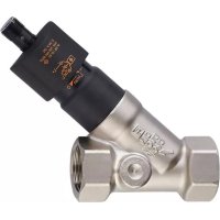
SBY334 - Flow sensor IFM - Free user manual and instructions
Find the device manual for free SBY334 IFM in PDF.


User questions about SBY334 IFM
0 question about this device. Answer the ones you know or ask your own.
Ask a new question about this device
Download the instructions for your Flow sensor in PDF format for free! Find your manual SBY334 - IFM and take your electronic device back in hand. On this page are published all the documents necessary for the use of your device. SBY334 by IFM.
USER MANUAL SBY334 IFM
Operating instructions
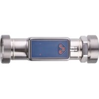
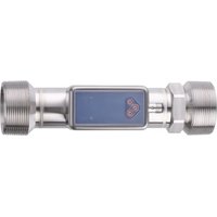
Mechatronic flow sensor
SBx3xx
Contents
1 Preliminary note.... 3
1.1 Symbols used.... 3
1.2 Warnings.... 3
2 Safety instructions 4
3 Transport, handling and storage 5
4 Intended use 6
4.1 Application area 6
5 Mounting 7
5.1 Process connection.... 7
5.2 Mounting accessories 8
5.3 Installation in case of water containing dirt 8
6 Electrical connection 9
7 Settings.... 10
7.1 Set the switch point on the unit.... 10
7.2 Carry out the flow adjustment.... 10
8 Operation.... 11
9 Maintenance, repair and disposal 12
1 Preliminary note
You will find instructions, technical data, approvals and further information using the QR code on the unit / packaging or at documentation.ifm.com.
1.1 Symbols used
Requirement
Instruction
Reaction, result
bold Designation of keys, buttons or indications
→ Cross-reference without link
→ Cross-reference with link


1.2 Warnings
Warnings indicate the possibility of personal injury and damage to property. This enables safe product handling. Warnings are graded as follows:

WARNING
Warning of serious personal injury
▷ If the warning is not observed, fatal and serious injuries are possible.

CAUTION
Warning of minor to moderate personal injury
▷ If the warning is not observed, minor to moderate injuries are possible.

ATTENTION
Warning of damage to property
▷ If the warning is not observed, damage to property is possible.
2 Safety instructions
- The unit described is a subcomponent for integration into a system.
- The system architect is responsible for the safety of the system.
-
The system architect undertakes to perform a risk assessment and to create documentation in accordance with legal and normative requirements to be provided to the operator and user of the system. This documentation must contain all necessary information and safety instructions for the operator, the user and, if applicable, for any service personnel authorised by the architect of the system.
-
Read this document before setting up the product and keep it during the entire service life.
- The product must be suitable for the corresponding applications and environmental conditions without any restrictions.
- Only use the product for its intended purpose (→ Intended use).
- Only use the product for permissible media.
- If the operating instructions or the technical data are not adhered to, personal injury and/or damage to property may occur.
- The manufacturer assumes no liability or warranty for any consequences caused by tampering with the product or incorrect use by the operator.
- Installation, electrical connection, set-up, operation and maintenance of the product must be carried out by qualified personnel authorised by the machine operator.
- Protect units and cables against damage.
3 Transport, handling and storage
▶ Store the device in its original packaging.
▶ When the device is to be stored again, use the original packaging.
▶ Otherwise, provide unused connections with either a mating connector or a protective cap and pack the device in suitable packaging.
▶ Observe the permissible ambient conditions for the device during storage (→ Technical data).
4 Intended use
The unit monitors liquid media.
It detects the volume flow (flow rate/time) according to the principle of differential pressure and switches the output.
The switch point is adjustable.
4.1 Application area
- Water
- Glycol solutions
- Cooling lubricants

Due to the technology-related susceptibility to interference in the range of the oscillator frequency (0.500...0.550 MHz), the switching output will switch incorrectly during the test according to EN 61000-4-6 with a test level of 10 V. After the malfunction, the equipment under test will automatically return to its original operation.

ATTENTION
Frost formation of the medium.
▷ The sensor may be damaged.
▶ Ensure that the medium in the sensor does not freeze during operation and transport.
5 Mounting

CAUTION
During installation or in case of a fault (e.g. housing damage) media under high pressure or hot media can leak from the system.
▷ Risk of injury caused by pressure or burns.
▶ Ensure that the system is free of pressure during installation.
▶ Ensure that no media can leak at the mounting location during installation.
▶ Equip the unit with suitable protection (e.g. cover) to avoid hazard to personnel from leaking media.
5.1 Process connection
- ▶ Avoid major changes of cross section on the inlet side.
▶ Fit the unit in the pipe in accordance with the flow direction (arrow) and tighten at the spanner flats.

Do not clamp the housing in a vice.
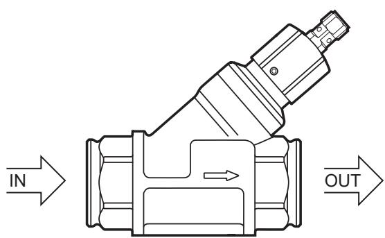
Fig. 1: Process connection
IN: Inlet
OUT: Outlet

Calming sections on the sensor's inlet or outlet side are not necessary.

The sensor can also prevent backflow.
5.2 Mounting accessories
▶ If necessary, fasten the device on a mounting plate (not supplied) from underneath:
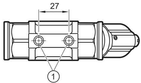
Fig. 2: Installation with mounting plate
1: Threaded hole M8 (depth 6 mm) on the bottom side of the unit
5.3 Installation in case of water containing dirt
▶ Use a 200-micron filter in front of the inlet (IN).
▶ Install sensor horizontally.
▶ Adhere to the inclination angle to the horizontal axis:

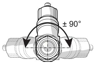
Fig. 3: Alignment in case of water containing dirt

In clean medium, installation in vertical pipes is also possible.
6 Electrical connection

The unit must be connected by a qualified electrician.
Observe the national and international regulations for the installation of electrical equipment.
Voltage supply according to SELV, PELV.
▶ Disconnect power.
▶ Connect the unit as follows:


Fig. 4: Wiring diagram (colours to DIN EN 60947-5-2)
BN: Brown
BU: Blue
BK: Black

Information on available sockets see: www.ifm.com.
7 Settings
There are 2 options to set the switch point:
- Set the switch point on the unit.
- Carry out the flow adjustment.

Fig. 5: Switch point setting
1: Yellow LED (switching status)
2: Cap
3: Fixing screw
4: Setting scale

Do not turn the cap beyond the maximum value of the setting range (→ Technical data) to avoid faulty switching.
7.1 Set the switch point on the unit
▶ Loosen the fixing screw.
▶ Turn the cap until the target value becomes visible on the setting scale.
▶ Tighten the fixing screw.
7.2 Carry out the flow adjustment
▶ Let the normal flow circulate in the installation.
▶ Loosen the fixing screw.
▶ Set the switch point by slowly turning the cap:
▷ the switch point has been reached as soon as the LED is on.
▶ Tighten the fixing screw.
8 Operation
After power on, the unit is ready for operation.
The unit detects the volumetric flow quantity and switches the output according to the setting.
- Output closed (LED = ON), if volumetric flow quantity ≥ switch point.
- Output open (LED = OFF), if volumetric flow quantity < switch point.
9 Maintenance, repair and disposal
The operation of the unit is maintenance-free.
Only the manufacturer is allowed to repair the unit.
▶ After use dispose of the device in an environmentally friendly way in accordance with the applicable national regulations.
In case of heavily polluted media:
▶ Mount a filter in front of the inlet (IN). Recommendation: use a 200-micron filter.
- 1 PRELIMINARY NOTE
- 1.1 SYMBOLS USED
- 1.2 WARNINGS
- 2 SAFETY INSTRUCTIONS
- 3 TRANSPORT, HANDLING AND STORAGE
- 4 INTENDED USE
- 4.1 APPLICATION AREA
- 5 MOUNTING
- 5.1 PROCESS CONNECTION
- 5.2 MOUNTING ACCESSORIES
- 5.3 INSTALLATION IN CASE OF WATER CONTAINING DIRT
- 6 ELECTRICAL CONNECTION
- 7 SETTINGS
- 7.1 SET THE SWITCH POINT ON THE UNIT
- 7.2 CARRY OUT THE FLOW ADJUSTMENT
- 8 OPERATION
- 9 MAINTENANCE, REPAIR AND DISPOSAL
Brand : IFM
Model : SBY334
Category : Flow sensor