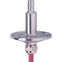
SF0516 - Flow sensor IFM - Free user manual and instructions
Find the device manual for free SF0516 IFM in PDF.


User questions about SF0516 IFM
0 question about this device. Answer the ones you know or ask your own.
Ask a new question about this device
Download the instructions for your Flow sensor in PDF format for free! Find your manual SF0516 - IFM and take your electronic device back in hand. On this page are published all the documents necessary for the use of your device. SF0516 by IFM.
USER MANUAL SF0516 IFM
Operating instructions
Flow sensor for connection to an evaluation unit
SF0516
Contents
1 Preliminary note 3
1.1 Symbols used 3
2 Safety instructions.... 4
3 Intended use 5
4 Installation.... 6
4.1 Process connection.... 6
4.2 Recommended mounting position.... 6
4.3 Use in hygienic areas according to 3-A....6
4.4 Interference.... 7
5 Electrical connection.... 8
6 Maintenance, repair and disposal 9
1 Preliminary note
You will find instructions, technical data, approvals and further information using the QR code on the unit / packaging or at documentation.ifm.com.
1.1 Symbols used
√ Requirement
Instructions
Reaction, result
[...] Designation of keys, buttons or indications
→ Cross-reference

Important note
Non-compliance may result in malfunction or interference.

Information
Supplementary note
2 Safety instructions
- The unit described is a subcomponent for integration into a system.
- The system architect is responsible for the safety of the system.
-
The system architect undertakes to perform a risk assessment and to create documentation in accordance with legal and normative requirements to be provided to the operator and user of the system. This documentation must contain all necessary information and safety instructions for the operator, the user and, if applicable, for any service personnel authorised by the architect of the system.
-
Read this document before setting up the product and keep it during the entire service life.
- The product must be suitable for the corresponding applications and environmental conditions without any restrictions.
- Only use the product for its intended purpose (→ Intended use).
- Only use the product for permissible media.
- If the operating instructions or the technical data are not adhered to, personal injury and/or damage to property may occur.
- The manufacturer assumes no liability or warranty for any consequences caused by tampering with the product or incorrect use by the operator.
- Installation, electrical connection, set-up, operation and maintenance of the product must be carried out by qualified personnel authorised by the machine operator.
- Protect units and cables against damage.
3 Intended use
The device monitors the flow in liquid and gaseous media in conjunction with a connected evaluation unit.
Suitable VS3000 evaluation units are listed as accessories at ifm.com.
The unit detects whether a preset flow value has been reached and signals this with a switching signal.
4 Installation
▶ Make sure that no pressure is applied to the system.
▶ Ensure that no media can leak at the mounting location during installation.
▶ Avoid deposits, accumulated gas and air in the pipe system.
4.1 Process connection

The device can be adapted to clamp connections 1" – 1.5" to DIN 32676 (ISO 2852).
▶ Secure the unit with a suitable clamp.
4.2 Recommended mounting position

Fig. 1: Recommended mounting position
▶ Mount the device ensuring that the sensor tip is completely surrounded by the medium (1).
▶ For horizontal pipes, mount the device on the side (2).
Installation from below only if the pipe is free of deposits. Mounting from above only if the pipeline is completely filled with medium.
▶ For vertical pipes, mount the device in the rising pipe, so that the medium flows upwards (3).
4.3 Use in hygienic areas according to 3-A
The sensor is suited for CIP (clean in place) when installed correctly.
▶ Observe the application limits (temperature and material resistance) according to the data sheet.
▶ Ensure that the installation of the unit in the system complies with 3-A guidelines.
▶ Use only process adapters with 3-A certification and marked with the 3-A symbol ( → Accessories at www.ifm.com).
▶ Use self-draining installation.

Fig. 2: Mounting position for use in hygienic areas in accordance with 3A
▶ The positioning of the sensor must be observed to ensure the mounting adapter will self-drain: Do not install the unit in positions 4 and 5.
4.4 Interference
Structures in the pipe, bends, valves, reducing pieces and the like affect the function of the unit.
▶ Adhere to the distances between sensor and interference.

Fig. 3: Inlet and outlet pipe lengths
IN: Upstream
OUT: Downstream
D: Outside diameter of the pipe
5 Electrical connection

The unit must be connected by a qualified electrician.
Observe the national and international regulations for the installation of electrical equipment.
Voltage supply according to SELV, PELV.
▶ Disconnect power.
▶ Connect the unit as follows:

Fig. 4: Wiring diagram
Colours to DIN EN 60947-5-2: BN = brown; BU = blue; BK = black; WH = white; GY = grey
6 Maintenance, repair and disposal
The operation of the unit is maintenance-free.
Only the manufacturer is allowed to repair the unit.
▶ After use dispose of the device in an environmentally friendly way in accordance with the applicable national regulations.
Cleaning the device
▶ Check the sensor tip for deposits from time to time. If necessary, clean it using a soft cloth. Stubborn build-up, such as lime, can be removed using a common vinegar cleaning agent.
For use in hygienic areas:
▶ Regularly check the seals between the device and the process adapter for deposits and damage.
▶ In case of soiling, clean the seals with a suitable cleaning liquid (e.g. alcoholic solution).
▶ Replace the seals if necessary.

The frequency of the seal replacement depends on the frequency of the cleaning cycles, the media temperature and the cleaning temperature.
▶ Define regular cleaning cycles according to the process requirements.
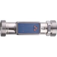
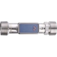
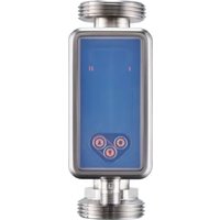
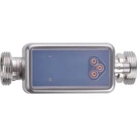
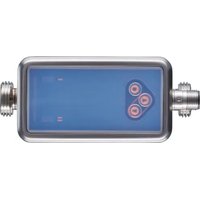
Brand : IFM
Model : SF0516
Category : Flow sensor