
O3D301 - Video camera IFM - Free user manual and instructions
Find the device manual for free O3D301 IFM in PDF.
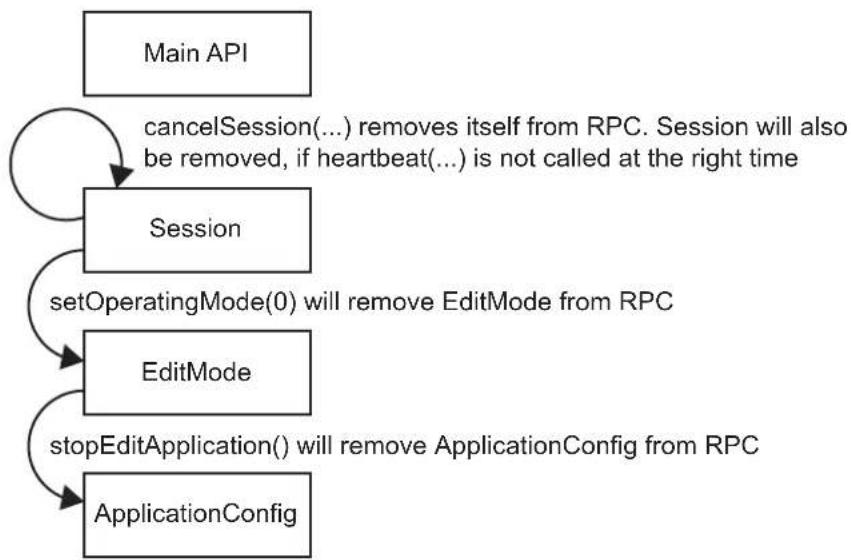
| Product Type | 3D Time-of-Flight (ToF) Camera |
| Brand | IFM |
| Model | O3D301 |
| Power Supply | 24 V DC via M12 5-pin connector, protection class III |
| Communication Interface | Ethernet (M12 connector, D-coded, 4-pole) |
| Trigger Input | Trigger input on pin 2, selectable rising/falling edge |
| Switching Outputs | 2 outputs (ready and cascade), PNP/NPN configurable |
| Distance Measurement Range | Up to 30 m (depending on settings, typically < 5 m for best resolution) |
| Resolution | Pixel matrix 176 x 132 (distance data) |
| Frame Rate | Up to 25 fps (varies with exposure time) |
| Light Source | Integrated infrared (800-900 nm) |
| Operating Temperature | Not specified, but surface ≤ ambient temperature + 25°C |
| Protection Rating | Not specified, indoor use only |
| Dimensions (approximate) | Approx. 60 x 60 x 80 mm (without lens) |
| Weight | Approx. 250 g |
| Mounting | Via 2 M5 screws or mounting kit (accessory) |
| Maintenance and Cleaning | Clean the front window with a lint-free cloth and glass cleaner |
| Safety | Electrical connection only by qualified electrician, indoor use, max altitude 2000 m |
| Spare Parts and Repairability | No user-serviceable parts; repair by manufacturer |
| Available Accessories | Mounting kit (E3D301), heat sink (E3D302), thermal conductor (E3D303) |
| Configuration Software | IFM Vision Assistant (free), ifm3Dlib, ROS |
| Certifications | EU Declaration of Conformity available at www.ifm.com |
Frequently Asked Questions - O3D301 IFM
User questions about O3D301 IFM
0 question about this device. Answer the ones you know or ask your own.
Ask a new question about this device
Download the instructions for your Video camera in PDF format for free! Find your manual O3D301 - IFM and take your electronic device back in hand. On this page are published all the documents necessary for the use of your device. O3D301 by IFM.
USER MANUAL O3D301 IFM
14.3.1 Sending Commands 25
14.3.2 Receiving Images 26
14.3.3 Image data 26
14.3.4 Additional Information for CONFIDENCE IMAGE 30
14.3.5 Configuration of PCIC Output 31
14.4 Process Interface Command Reference 36
14.4.1 a Command (activate application) 36
14.4.2 A? Command (occupancy of application list) 36
14.4.3 c Command (upload PCIC output configuration) 37
14.4.4 C? Command (retrieve current PCIC configuration). 37
14.4.5 E? Command (request current error state). 37
14.4.6 G? Command (request device information) 38
14.4.7 H? Command (return a list of available commands). 39
14.4.8 I? Command (request last image taken). 40
14.4.9 o Command (set logic state of a ID). 40
14.4.10 O? Command (request state of a ID) 41
14.4.11 p Command (turn PCIC output on or off) 41
14.4.12 S? Command (request current decoding statistics) 42
14.4.13 t Command (execute asynchronous trigger). 42
14.4.14 T? Command (execute synchronous trigger) 43
14.4.15 v Command (set current protocol version) 43
14.4.16 V? Command (request current protocol version) 43
14.5 Error codes 44
14.6 XML-RPC Command Reference 45
14.6.1 Parameter API 45
14.6.2 Main Object 46
14.6.3 Session Object 49
14.6.4 Edit Mode Object 51
14.6.5 Device Config Object 52
14.6.6 Device/Network Config Object 56
14.6.7 Application Config Object 56
14.6.8 Application/Imager Config Object 58
14.6.9 Image Settings and Filter Parameters 65
Copyright
Microsoft, Windows, Windows Vista, Windows 7, Windows 8, Windows 10, Windows 10, Windows 10, Windows 10, Windows 10, Windows 10, Windows 10, Windows 10, Windows 10, Windows 10, Windows 10, Windows 10, Windows 10,
This product can contain Free Software or Open Source Software from various software developers which is subject to the following licenses: General Public License version 1, version 2 and version 3 (General Public License version 3 in conjunction with the GNU Compiler Collection Runtime Library Exception version 3.1), Lesser General Public License version 2.1, Lesser General Public License version 3, Berkeley Software Distribution ("This product includes software developed by the University of California, Berkeley and its contributors"), The Academic Free License version 2.1. For the components subject to the General Public License in their respective versions the following applies:
This program is free software: you can redistribute it and/or modify it under the terms of the GNU General Public License as published by the Free Software Foundation. If version 1 applies to the software: either version 1 of the License or (at your option) any later version; if version 2 (or 2.1) applies to the software: either version 2 (or 2.1) of the License or (at your option) any later version; if version 3 applies to the software: either version 3 of the License or (at your option) any later version. The following disclaimer of the software developers applies to the software components that are subject to the General Public License or the Lesser General Public License in their respective versions: The Free Software is distributed in the hope that it will be useful, but WITHOUT ANY WARRANTY; without even the implied warranty of MERCHANTABILITY or FITNESS FOR A PARTICULAR PURPOSE. See the GNU General Public License and the GNU Lesser General Public License for more details.
The responsibility of ifm electronic gmbh for ifm products, in the case of product-specific software, remains unaffected by the above disclaimer. Please note that the firmware for the ifm products is in some cases provided free of charge. The price of the ifm products has then to be paid for the respective device itself (hardware) and not for the firmware. For the latest information on the license agreement for your product please visit www.ifm.com
For binaries that are licensed under any version of the GNU General Public License (GPL) or the GNU LGPL you may obtain the complete corresponding source code of the GPL software from us by sending a written request to: opensource@ifm.com or to ifm electronic gmbh Friedrichstraße 1, 45128 Essen, Germany.
We charge €30 for each request. Please write "source for product Y" in the memo line of your payment. Your request should include (i) the name of the covered binary, (ii) the name and the version number of the ifm product, (iii) your name and (iv) your return address.
This offer is valid to anyone in receipt of this information.
This offer is valid for at least three years (from the date you received the GLP/LGPL covered code).
The following ports are required for the camera configuration using XML-RPC and for receiving data on the process interface. They must not be blocked by a firewall or router.
- TCP/HTTP: 80
TCP:50010
If the ifm Vision Assistant is used, the following additional ports must also be available:
UDP:3321
- TCP/HTTP: 8080
It is possible to configure another port than 50010 for the process interface. If a different port is used, it must not be blocked either.
14.2 XML-RPC Interface
In case the O3D3xx camera should not be configured by the "ifmVisionAssistant", the XML-RPC interface can be used instead.

General information about XML-RPC is found on the website http://xmlrpc.scripting.com/spec
To send a command via the XML-RPC interface the command is in a special layout. In this command, linefeeds and carriage returns are essential.

Every command which is sent via the XML-RPC interface must end with carriage return <CR> and linefeed <LF> .
Several commands will use different URLs in the XML-RPC header.
14.2.1 Sample XML-RPC command
All following XML-RPC commands will have this type of layout:
POST /RPC3 HTTP/1.0<CR><LF>
User-Agent: Frontier/5.1.2 (WinNT)<CR><LF>
Host: betty.userland.com<CR><LF>
Content-Type: text/xml<CR><LF>
Content-length: 181<CR><LF>
<CR><LF>
<?xml version="1.0"?><CR><LF>
<methodCall><CR><LF>
<methodName>examples.getName</methodName><CR><LF>
<params><CR><LF>
<param><CR><LF>
<value><i4>41</i4></value><CR><LF>
</param><CR><LF>
</params><CR><LF>
</methodCall><CR><LF>
The following example contains one O3D3xx command: POST /api/rpc/v1/com.ifm.efector/ HTTP/1.1 <CR><LF> User-Agent: Frontier/5.1.2 (WinNT)<CR><LF> Host: 192.168.0.69<CR><LF> Content-Type: text/xml<CR><LF> Content-length: 94<CR><LF> <CR><LF> <?xml version="1.0"?><CR><LF> <methodCall><CR><LF> <MethodName>getParameter</methodName><CR><LF> </methodCall><CR><LF>
14.2.2 XML-RPC Objects
To communicate and to configure the device via XML-RPC the XML-RPC commands have to use different XML-RPC objects. Different commands need different XML-RPC objects (see XML-RPC command references).
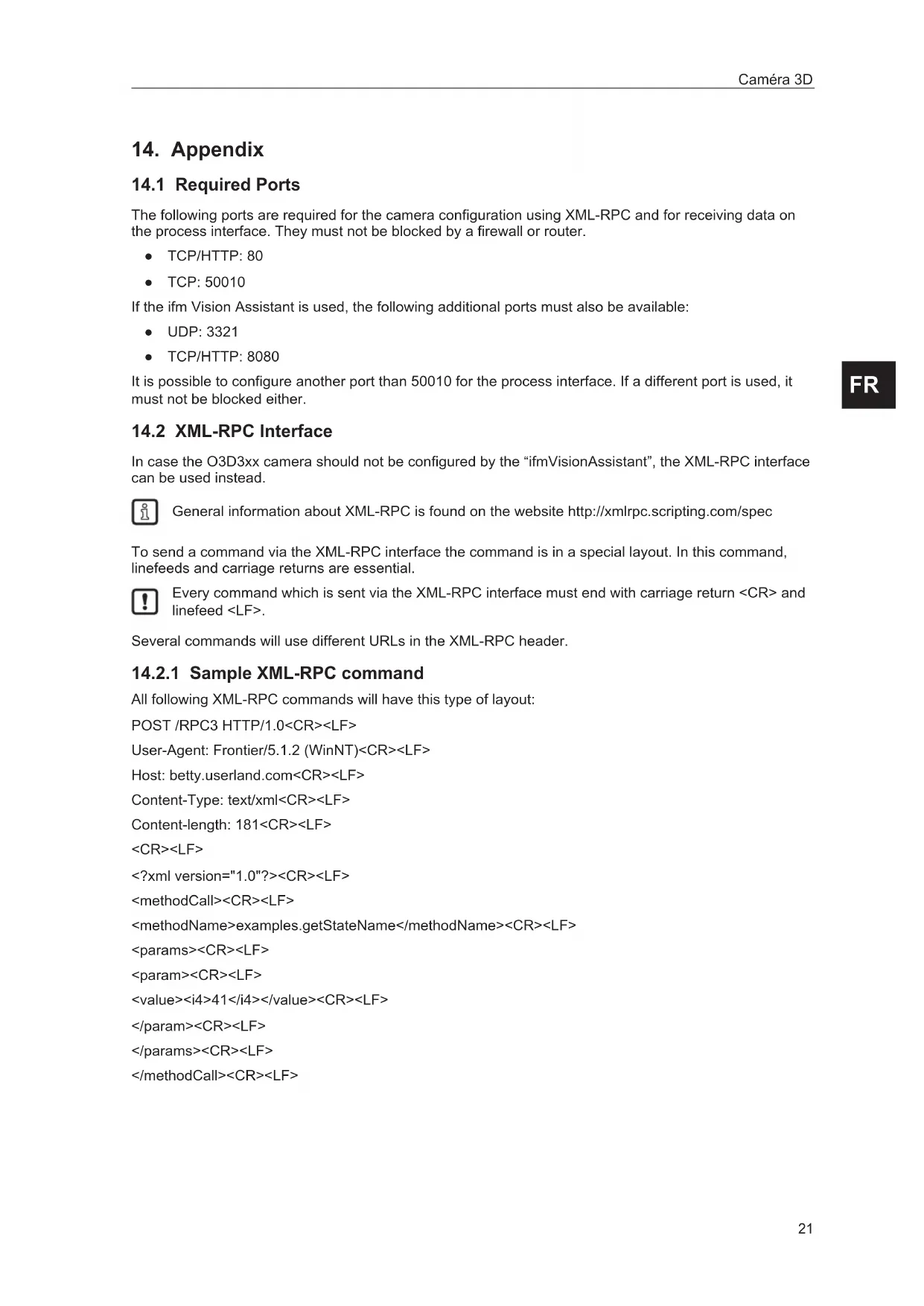
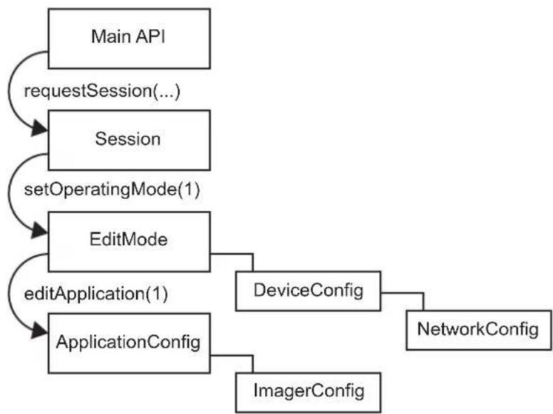
The interface of O3D3xx is structured in an object-oriented way. Some of the objects are available all the time, others are only available after bringing the device into a special mode by calling a method on an already available object. This mechanism is used to create system requirements (e.g. password protection).

It could be necessary to send heartbeats so that there will be no session timeout.
The following diagram should give an overview how objects are related to each other and which methods must be called to make others available:
Main Object
Object-URI:/api/rpc/v1/com.ifm.efector/
This is the main object of RPC. It contains methods to open a session. The session contains methods for activating the edit mode. Most of its methods are only getters, because it should be possible to protect editing with a password.
Session Object
Object URI e.g.: /api/rpc/v1/com.ifm.efactor/session_d21c80db5bc1069932fbb9a3bd841d0b/
The URL part "d21c80db5bc1069932fbbb9a3bd841d0b" is the session ID. It is returned by the command "requestSession" of the main object. If the command "requestSession" is called without a user-defined session ID, which can be passed as a parameter, a random session ID is generated automatically.
EditMode Object
Object URI e.g.: /api/rpc/v1/com.ifm.efector/session_d21c80db5bc1069932fbb9a3bd841d0b/edit/
This object is only available if the device is in the edit operating mode. The index of applications must be between 1 and 32. The device must only support 32 applications and the indexes must start at 1.
DeviceConfig Object
Object-URI e.g.: /api/rpc/v1/com.ifm.efector/session_d21c80db5bc1069932fbb9a3bd841d0b/edit/device/
Device/NetworkConfig Object
Object URI e.g.: /api/rpc/v1/com.ifm.efector/session_d21c80db5bc1069932fbb9a3bd841d0b/edit/device/network/
Application Config Object (editorable application)
Object URI e.g.: /api/rpc/v1/com.ifm.efector/session_d21c80db5bc1069932fbb9a3bd841d0b/edit/application/
Application/Imager Config Object (O3D3xx)
Object URI e.g.: /api/rpc/v1/com.ifm.efector/session_d21c80db5bc1069932fbb9a3bd841d0b/edit/application/imager_001/
As there is only one imager config on O3D3xx, the ID must be fixed to "001". Data of this object is persistently saved when calling "save" on the application config object. The imager config RPC object has multiple sub-types. Only parameters relevant for a specific type are available while it is active. They are based on frequency (extending the distance) and integration intervals (extending the measurement details).
Type names, based on GUI draft (under 5 metres -> single frequency, up to 30 metres -> double frequency, more than 30 metres -> triple frequency.):
under5m_low
under5m_moderate
under5m_high
upto30m_low
upto30m/moderate
upto30m_high
morethan30m_low
morethan30m_moderate
Image Settings and Filter Parameters
There is an RPC object for spatial filter parameters in each imager configuration.
Object URI e.g.: /api/rpc/v1/com.ifm.effector/session_d21c80db5bc1069932fbb9a3bd841d0b/edit/application/imager_001/spatialfilter
There is an RPC object for temporal filter parameters in each imager configuration.
Object URI e.g.: /api/rpc/v1/com.ifm.efector/session_d21c80db5bc1069932fbb9a3bd841d0b/edit/application/imager_001/temporalfilter
Data of these objects is persistently saved when calling "save" on application config object.
14.3 Process Interface
The process interface is used during the normal operation mode to get operational data (e.g. 3D images, process values) from the O3D3xx.
14.3.1 Sending Commands
For sending commands via the process interface the commands have to be sent with a special protocol and as ASCII character strings. This protocol conforms to the version 3 of the O2V/O2D products.
Structure of the protocol:
| Abbreviation Description ASCII code (dec) ASCII code (hex) | ||
| CR Carriage Return 13 D | ||
| LF Linefeed 10 A | ||
| < > Marking of a placeholder (e.g. <code> is a placeholder for code) | ||
| [ ] Optional argument (possible but not required) |
| Command Description |
| <content> It is the command to the device (e.g. trigger the unit). |
| <ticket> It is a character string of 4 digits between 0-9. If a message with a specific ticket is sent to the device, it will reply with the same ticket. A ticket number must be >0999. Use a ticket number from the range 1000 - 9999. |
| <length> It is a character string beginning with the letter 'L' followed by 9 digits. It indicates the length of the following data (<ticket><content>CR LF) in bytes. |
They are different protocol versions available:
| Version | Input format Output format | |
| V1 | as input | |
| V2 | as input | |
| V3 | as input | |
| V4 | CR LF |

The default protocol version is "V3". It is recommended to use protocol version 3 for machine to machine communication. This is due to the fact that only version 3 supports asynchronous messages and provides length information.
Ticket numbers for asynchronous messages:
| Ticket number | Description |
| 0000 | Asynchronous results |
| 0001 | Asynchronous error messages / codes |
| 0010 | Asynchronous notifications / message codes |

14.3.2 Receiving Images
For receiving the image data a TCP/IP socket communication is established. The default port number is 50010. The port number may differ based on the configuration. After opening the socket communication, the O3D3XX device will automatically (if the device is in free run mode) send the data through this socket to the TCP/IP client (PC).
PCIC output per frame. The following data is submitted in this sequence:
| Component Content | |
| Ticket and length information (→14.4.14) | |
| Ticket „0000“ | |
| Start sequence String "star" (4 bytes) | |
| Normalised amplitude image | 1 image |
| Output format: 16-bit unsigned integer | |
| Distance image | 1 image |
| Output format: 16-bit integer. Unit: mm. | |
| X image | 1 image |
| Output format: 16-bit signed integer. Unit: mm. | |
| Y image | 1 image |
| Output format: 16-bit signed integer. Unit: mm. | |
| Z image | 1 image |
| Output format: 16-bit signed integer. Unit: mm. | |
| Confidence image | 1 image |
| Output format: 8-bit unsigned integer | |
| Diagnostic data | |
| Stop sequence String "stop" (4 bytes) | |
| Ticket signature <CR><LF> |
14.3.3 Image data
For every image there will be a separate chunk. The chunk is part of the response frame data of the process interface.
The header of each chunk contains different kinds of information. This information is separated into bytes. The information contains e.g. the kind of image which will be in the "PIXEL_DATA" and the size of the chunk.
| Offset Name | Description Size [byte] | ||
| 0x0000 | CHUNK_TYPE Defines the type of the chunk. For each distinct chunk an own type is defined. | 4 | |
| 0x0004 | CHUNK_SIZE Size of the whole image chunk in bytes. After this count of bytes the next chunk starts. | 4 | |
| 0x0008 | ADER_SIZE Number of bytes starting from 0x0000 until PILXEL_DATA. | 4 | |
| 0x000C | HEADER_VERSION | Version number of the header | 4 |
| 0x0010 | IMAGE_WIDTH | Image width in pixel 4 | |
| 0x0014 | IMAGE_HEIGHT | Image height in pixel 4 | |
| 0x0018 | PIXEL_FORMAT | Pixel format 4 | |
| 0x001C | TIME_STAMP Time stamp | in microseconds (deprecated) 4 | |
| 0x0020 | FRAME_COUNT Frame counter 4 | ||
| 0x0024 | STATUS_CODE Errors of the device 4 | ||
| 0x0028 | TIME_STAMP_SEC Time stamp in seconds 4 | ||
| 0x002C | TIME_STAMP_NSEC Time stamp in nanoseconds 4 | ||
| 0x0030 | PIXEL_DATA | The pixel data in the given type and dimension of the image. Padded to 4-byte boundary. | 4 |
Available chunk types:
| Constant | Value | Description |
| RADIAL_distance_IMAGE | 100 | Each pixel of the distance matrix denotes the ToF distance measured by the corresponding pixel or group of pixels of the imager. The distance value is corrected by the camera's calibration, excluding effects caused by multipath and multiple objects contributions (e.g. "flying pixels"). Reference point is the optical centre of the camera inside the camera housing.Invalid PMD pixels (e.g. due to saturation) have a value of zero.Data type: 16-bit unsigned integer (little endian)Unit: millimetres |
| NORM_AMPLITU卖家 | 101 | Each pixel of the normalized amplitude image denotes the raw amplitude (see amplitude image below for further explanation), normalized to exposure time. Furthermore, vignetting effects are compensated, ie the darkening of pixels at the image border is corrected. The visual impression of this grayscale image is comparable to that of a common 2D camera.Invalid PMD pixels (e.g. due to saturation) have an amplitude value of 0.Data type: 16-bit unsigned integer |
| AMPLITUDE_IMAGE | 103 | Each pixel of the amplitude matrix denotes the amount of modulated light (i.e. the light from the camera's active illumination) which is reflected by the appropriate object. Higher values indicate higher PMD signal strengths and thus a lower amount of noise on the corresponding distance measurements. The amplitude value is directly derived from the PMD phase measurements without normalisation to exposure time. In multiple exposure mode, the lack of normalisation may lead (depending on the chosen exposure times) to inhomogeneous amplitude image impression, if a certain pixel is taken from the short exposure time and some of its neighbours are not.Invalid PMD pixels (e.g. due to saturation) have an amplitude value of 0.Data type: 16-bit unsigned integer |
| GRAYSCALE_IMAGE | 104 | Each pixel of the amplitude matrix denotes the amount of modulated light which is reflected by the appropriate object (i.e. the light from the camera's active illumination). Higher values indicate higher PMD signal strengths and thus a lower amount of noise on the corresponding distance measurements. The amplitude value is directly derived from the PMD phase measurements without normalisation to exposure time. |
| Constant Value Description | ||
| CARTESIAN_X Component | 200 The X matrix denotes the X component of the Cartesian coordinate of a PMD 3D measurement. The origin of the camera's coordinate system is in the middle of the lens' front glass, if the extrinsic parameters are all set to 0.Data type: 16-bit signed integerUnit: millimetres | |
| CARTESIAN_Y Component | 201 The Y matrix denotes the Y component of the Cartesian coordinate of a PMD 3D measurement. The origin of the camera's coordinate system is in the middle of the lens' front glass, if the extrinsic parameters are all set to 0.Data type: 16-bit signed integerUnit: millimetres | |
| CARTESIAN_Z Component | 202 The Z matrix denotes the Z component of the Cartesian coordinate of a PMD 3D measurement. The origin of the camera's coordinate system is in the middle of the lens' front glass, if the extrinsic parameters are all set to 0.Data type: 16-bit signed integerUnit: millimetres | |
| CARTESIAN_ALL 203 CARTESIAN | X_COMPONENT, CARTESIAN_Y_COMPONENT, CARTESIAN_Z_COMPONENT | |
| UNIT_VECTOR_ALL 223 | The unit vector matrix contains 3 values [ex, ey, ez] for each PMD pixel, i.e. the data layout is [ex_1,ey_1,ez_1,... ex_N,ey_N, ez_N], where N is the number of PMD pixels.Data type: 32-bit floating point number (3x per pixel) | |
| CONFIDENCE_IMAGE | See Additional Information for Image Data (→14.3.4) | |
| DIAGNOSTIC 302 See Receiving Images (→14.3.2) | ||
| JSON_DIAGNOSTIC 305 | Items with JSON formatted diagnostic data is formatted like this:{"AcquisitionDuration": 20.391, "EvaluationDuration": 37.728, "FrameDuration": 37.728, "FrameRate": 15.202, "TemperatureIllum": 52.9}Unit for durations: millimetresUnit for framereates: HzUnit for temperature: °C | |
| EXTRINSIC_CALIB 400 | The transformation from one cartesian coordinate system to another is defined by a 6 degrees of freedom vector (DOF): [trans_x, trans_y, trans_z, rot_x, rot_y, rot_z]. Let R be the product of the common "clockwise" 3D-rotation matrices: R = Rx*Ry*RzThe transformation of a point P is specified by P_t = R*P + [trans_x, trans_y, trans_z']. The device extrinsic calibration can be set by the user, but it may be changed by an automatic calibration feature of the device. Data type: 32-bit floating point number (little endian) Unit for trans_x, trans_y, trans_z: millimetres Unit for rot_x, rot_y, rot_z: ° | |
| JSON_MODEL 500 Model | data in JSON | |
| MODEL_ROIMASK 501 | ROI mask for internal debugging purposes | |
| SNAPSHOT_IMAGE 600 | Snapshot | image |
Pixel format:
| Constant Value Description | ||
| FORMAT_8U 0 8-bit unsigned integer | ||
| FORMAT_8S 1 8-bit signed integer | ||
| FORMAT_16U 2 16-bit unsigned integer | ||
| FORMAT_16S 3 16-bit signed integer | ||
| FORMAT_32U 4 32-bit unsigned integer | ||
| FORMAT_32S 5 32-bit signed integer | ||
| FORMAT_32F 6 32-bit floating point number | ||
| FORMAT_64U 7 64-bit unsigned integer | ||
| FORMAT_64F 8 64-bit floating point number | ||
| Reserved | 9 N/A | |
| FORMAT_32F_3 10 | Vector with 3x32-bit floating point number | |
14.3.4 Additional Information for CONFIDENCE_IMAGE
Further information for the confidence image:
| Bit Value Description | ||
| 0 1 = pixel invalid Pixel invalid | The pixel is invalid. To determine whether a pixel is valid or not only this bit needs to be checked. The reason why the bit is invalid is recorded in the other confidence bits. | |
| 1 1 = pixel saturated Pixel is saturated | Contributes to pixel validity: yes | |
| 2 1 = bad A-B symmetry A-B pixel symmetry | The A-B symmetry value of the four phase measurements is above threshold.Remark: This symmetry value is used to detect motion artefacts. Noise (e.g. due to strong ambient light or very short integration times) or PMD interference may also contribute.Contributes to pixel validity: yes | |
| 3 1 = amplitude below minimum amplitude threshold | Amplitude limitsThe amplitude value is below minimum amplitude threshold.Contributes to pixel validity: yes | |
| 4+5 Bit 5, bit 40 0 0 = unused0 1 = shortest exposure time (only used in 3 exposure mode)1 0 = middle exposure time in 3 exposure mode, short exposure in double exposure mode1 1 = longest exposure time (always 1 in single exposure mode) | Exposure time indicatorThe two bits indicate which exposure time was used in a multiple exposure measurement.Contributes to pixel validity: no | |
| 6 1 = pixel is clipped Clipping box on 3D dataIf clipping is active this bit indicates that the pixel coordinates are outside the defined volume.Contributes to pixel validity: yes | ||
| 7 1 = suspect/defective pixel Suspect pixelThis pixel has been marked as "suspect" or "defective" and values have been replaced by interpolated values from the surroundings.Contributes to pixel validity: no | ||
14.3.5 Configuration of PCIC Output
The user has the possibility to define his own PCIC output. This configuration is only valid for the current PCIC connection. It does not affect any other connection and will get lost after disconnecting.
For configuring the PCIC output a "flexible" layouter concept is used, represented by a JSON string. The format of the default configuration is as follows:
{
    "layouter": "flexible",
    "format": { "dataencoding": "ascii" },
    "elements": [
        { "type": "string", "value": "star", "id": "start_string" },
        { "type": "blob", "id": "normalized_amplitude_image" },
        { "type": "blob", "id": "x_image" },
        { "type": "blob", "id": "y_image" },
        { "type": "blob", "id": "z_image" },
        { "type": "blob", "id": "confidence_image" },
        { "type": "blob", "id": "diagnostic_data" },
        { "type": "string", "value": "stop", "id": "end_string" }
    ]
}
This string can be retrieved by the C? command, altered and sent back using the c command.
The layout software has the following main object properties:
| Name Description | Details | |
| layouter Defines the basic data output format. So far only "flexible" is supported | Type: string | |
| format Defines format details, the definitions in the main object are the defaults for any of the following data elements (e.g. if it says dataencoding=binary, all data elements should be binary encoded instead of ASCII). | Type: object | |
| elements List of data elements which must be written. Type: array of objects | ||
The actual data is defined within the "elements" properties and may consist of these settings:
| Name Description Details | ||
| type Defines the type of data which must be written. The data might be stored in a different type (e.g. stored as integer but should be output as Float32) The type "records" will need some special handling. | Type: string | |
| id Defines an identifier for this data element. If there is no fixed value (property "value"), the data should be retrieved via id. | Type: string | |
| value Optional property for defining a fixed output value. Type: any JSON value | ||
| format Type-dependent option for fine-tuning the output format. E.g. cut an integer to less than 4 bytes. | Type: object | |
Available values for the type property:
| Type Description | on |
| records Define | defines that this element represents a list of records. |
| If type is set to "records", there must be an "elements" property. | |
| The "elements" property defines which data should be written per record. | |
| string Data is | written as string. |
| Most of the time this will be used with "value" property to write fixed start, end or delimiter text. | |
| Text encoding should be UTF8 if there is nothing else specified in format properties. | |
| float32 Data | is written as floating point number. |
| This has a lot of formatting options (at least with "flexible" layout software) | |
| See following section about format properties. | |
| uint32 Data | is written as integer. |
| This has a lot of formatting options (at least with "flexible" layout software) | |
| See following section about format properties. | |
| int32 Data is | written as integer. |
| This has a lot of formatting options (at least with "flexible" layout software) | |
| See following section about format properties. | |
| uint16 Limits | the output to two bytes in binary encoding, besides the binary limitation it acts like uint32. |
| int16 Limits | the output to two bytes in binary encoding, besides the binary limitation it acts like int32. |
| uint8 Limits | the output to one byte in binary encoding, besides the binary limitation it acts like uint32. |
| int8 Limits | the output to one byte in binary encoding, besides the binary limitation it acts like int32. |
| blob Data is | written as a BLOB (byte by byte as if it came from the data provider). |
| (Binary Large Object) |
Depending on the desired data format the user may tune his output data with further "format" properties.
Common format properties:
| Format properties | Allowed values Default | |
| dataencoding "ascii" or "binary" can be defined in top-level-object and overwritten by element objects. | "ascii" | |
| scale "float value with decimal separator" to scale the results for output byte width | 1.0 | |
| offset "float value with decimal separator" 0.0 | ||
Binary format properties:
| Format properties | Allowed values Default | |
| order | Little, big and network | Little |
ASCII format properties:
| Format properties Allowed | wed values Default | |
| width Output width. | If the resulting value exceeds the width field the result will not be truncated. | 0 |
| fill Fill character " " | ||
| precision Precision | is the number of digits behind the decimal separator. 6 | |
| displayformat Fixed, scientific Fixed | ||
| alignment Left, right | Right | |
| decimalseparator 7-bit characters for e.g. ".". ." | ||
| base Defines if the | output should be: • binary (2) • octal (8) • decimal (10) • hexadecimal (16) | 10 |
Example of a format configuration of the temperature (id: temp_illu) element.
- Illumination temperature like this "33,5":
c000000226 {"layouter": "flexible", "format": {"dataencoding": "ascii"},
"elements": [ {"type": "float32", "id": "temp_illu", "format": {"width": 7,
"precision": 1, "fill": "_", "alignment": "left", "decimalseparator": "","]}
} ]
- Illumination temperature as binary (16-bit integer, 1 / 10^ ):
c000000194{ "layouter": "flexible", "format": {"dataencoding": "ascii"},
    "elements": [ { "type": "int16", "id": "temp_illu", "format": \{
    "dataencoding": "binary", "order": "network", "scale": 10 \} ] ]
- Illumination temperature in ^ F (e.g. "92.3 Fahrenheit"):
c000000227{ "layouter": "flexible", "format": {"dataencoding":"ascii" }, "elements": [ {"type": "float32", "id": "temp_illu", "format": {"precision": 1, "scale": 1.8, "offset": 32} ], { "type": "string", "value": "Fahrenheit" } ] }
The following element IDs are available:
| ID Description Native data type | ||
| activeapp_id Active application, shows which of the 32 application-configurations is currently active | 32-bit unsigned integer | |
| all_caresian_vector_matrices | All Cartesian images (X+Y+Z) concatenated to one package | 16-bit signed integer |
| all_unit_vector_matrices | Matrix of unit vectors. Each element consists of a 3 component vector [e_x, e_y, e_z] | Float32 |
| amplitude_image PMD raw amplitude image 16-bit unsigned | integer | |
| confidence_image Confidence image 8-bit unsigned | integer | |
| distance_image Radial distance image 16-bit unsigned | integer unit: millimetres | |
| evaltime Evaluation time for current frame in milliseconds 32-bit unsigned | integer | |
| extrinsic Calibration Extrinsic calibration, consisting of 3 translation parameters (unit: millimeters) and 3 angles (unit: degree): [t_x, t_y, t_z, alpha_x, alpha_y, alpha_z] | Float32 | |
| framerate Current frame rate in Hz Float32 | ||
| normalized_amplitude_image | Normalized amplitude image | 16-bit unsigned integer |
| temp_front1 | Invalid temperature, the output is 3276.7 | Float32, unit: °C |
| temp_illu | Temperature measured in the device while capturing this result Measured on the illumination board | Float32, unit: °C |
| x_image | Cartesian coordinates for each pixel | 16-bit signed integer |
| y_image | Each dimension is a separate image | |
| z_image |
For the main object on devices with statistics feature the following IDs are available:
| ID Description Native data type | ||
| statistics_overall_count Allows the | user to output the statistics value with the result of the frame, maps to ModelResults: adv_statistics.number_of Frames | uint32 |
| statistics Passed_count Allows the | user to output the statistics value with the result of the frame, maps to ModelResults: adv_statistics.number_of Passed Frames | uint32 |
| statistics_failed_count Allows the | user to output the statistics value with the result of the frame, maps to ModelResults: adv_statistics.number_of_FAILEDFrames | uint32 |
| statistics_aborted_count Allows the | user to output the statistics value with the result of the frame, maps to ModelResults: adv_statistics.number_of_abortedFrames | uint32 |
| statistics Acquisition_time_min Allows | allows the user to output the statistics value with the result of the frame,maps to ModelResults: adv_statistics.frame_acquisition.min | float32 |
| statistics Acquisition_time_mean | Allows the user to output the statistics value with the result of the frame,maps to ModelResults: adv_statistics.frame_acquisition.mean | float32 |
| statistics Acquisition_time_max | allows the user to output the statistics value with the result of the frame,maps to ModelResults: adv_statistics.frame_acquisition.max | float32 |
| statistics_evaluation_time_min Allows | allows the user to output the statistics value with the result of the frame,maps to ModelResults: adv_statistics.frame_evaluation.min | float32 |
| statistics_evaluation_time_mean | Allows the user to output the statistics value with the result of the frame,maps to ModelResults: adv_statistics.frame_evaluation.mean | float32 |
| statistics_evaluation_time_max | allows the user to output the statistics value with the result of the frame,maps to ModelResults: adv_statistics.frame_evaluation.max | float32 |
| statistics_frame_duration_min Allows | allows the user to output the statistics value with the result of the frame,maps to ModelResults: adv_statistics.frame_duration.min | float32 |
| statistics_frame_duration_mean | allows the user to output the statistics value with the result of the frame,maps to ModelResults: adv_statistics.frame_duration.mean | float32 |
| statistics_frame_duration_max | allows the user to output the statistics value with the result of the frame,maps to ModelResults: adv_statistics.frame_duration.max | float32 |
14.4 Process Interface Command Reference

All received messages which are sent because of the following commands will be sent without "start"/stop" at the beginning or ending of the string.
14.4.1 a Command (activate application)
| Command | a<application number> | |
| Description Activates the selected | application | |
| Type Action | ||
| Reply * | ||
| ! · Application not available | · <application number> contains wrong value · External application switching activated · Device is in an invalid state for this command, e.g. configuration mode | |
| ? Invalid command length | ||
| Note <application number> | 2 digits for the application number as decimal value |
14.4.2 A? Command (occupancy of application list)
| Command | A? | |
| Description Requests the occupancy of the application list | ||
| Type Request | ||
| Reply <amount><t><number active application><t> ... <number><t><number> | ||
| ? Invalid command length | ||
| ! Invalid state (e.g. no application active) | ||
| Note <amount> | char string with 3 digits for the amount of applications saved on the device as decimal number <t> tabulator (0x09) <numactiveapplication> 2 digits for the active application <num> 2 digits for the application number | The active application is repeated within the application list. |
14.4.3 c Command (upload PCIC output configuration)
| Command | c<length><configuration> | |
| Description Uploads a PCIC output | configuration lasting this session | |
| Type Action | ||
| Reply* | ||
| ! · Error in configuration | Wrong data length | |
| ? Invalid command length | ||
| Note<length> | 9 digits as decimal value for the data length | |
| <configuration> | ||
| configuration data |
14.4.4 C? Command (retrieve current PCIC configuration)
| Command | C? | |
| Description Retrieves the current PCIC configuration | ||
| Type Request | ||
| Reply <length><configuration> | ||
| ? Invalid command length | ||
| Note <length> | 9 digits as decimal value for the data length | |
| <configuration> | ||
| configuration data | ||
14.4.5 E? Command (request current error state)
| Command | E? | |
| Description Requests the current error state | ||
| Type Request | ||
| Reply <code> | ||
| !Invalid state (e.g. configuration mode) | ||
| ?Invalid command length | ||
| Note • <code> | Error code with 8 digits as a decimal value. It contains leading zeros. | |
14.4.6 G? Command (request device information)
| Command | G? | ||
| Description Requests device information | |||
| Type Request | |||
| Reply <vendor><t><article numbe>><t><name><t><location><t><description><t></ip><sub>,<sub>subnet mask></t></sub>><gateway><t><MAC><t></DHCP></t><port number> | |||
| Note • <vendor> | IFM ELECTRONICTabulator (0x09)article number>e.g. O3D300<name>UTF8 Unicode string<location>UTF8 Unicode string<description>UTF8 Unicode string<ip>IP address of the device as ASCII character stinge.g. 192.168.0.96<sub>,<sub>port number></sub>port number of the XML-RPC<sub>,<sub>,<sub>,<sub>,<sub>,<sub>,<sub>,<sub>,<sub>,<sub>,<sub>,<sub>,<sub>,<sub>,<sub>,<sub>,<sub>,<sub>,<sub>,<sub>,<sub>,<sub>,<sub>,<sub>,<sub>,<sub>,<sub>,<sub>,<sub>,<sub>,<sub>,<sub>,<sub>,<sub>,<br><br><br><br><br><br><br><br><br><br><br><br><br><br><br><br><br><br><br><br><br><br><br><br><br><br><br><br><br><br><br><br><br><br><br><br><br><br><br><br><br><br><br><br><br><br><br><br><br><br><br></t" for off and "1" for on | ||
14.4.7 H? Command (return a list of available commands)
| Command | H? | |
| Description Returns a list of available commands | ||
| Type Request | ||
| Reply H? - show this list | t - execute TriggerT? - execute Trigger and wait for datao<io-id><io-state> - sets IO stateO<io-id>? - get IO stateI(image-id>? - get last image of defined typeA? - get application listp<state> - activate / deactivate data outputa<application number> - set active applicationE? - get last errorV? - get current protocol versionv<version> - sets protocol versionc<length of configurationfile><configuration file> - configures process date formattingC? - show current configurationG? - show device informationS? - show statisticsL? - retrieves the connection IDf<id><reserved><value> - set parameter value |
14.4.8 I? Command (request last image taken)
| Command | I<image-ID>? | ||
| Description Request last image taken | |||
| Type Request | |||
| Reply <length><image data> | |||
| ! • No image available | • Wrong ID | ||
| ? • Invalid command length | |||
| Note <image-ID> | 2 digits for the image type | Valid image ID:01 - amplitude image02 - normalised amplitude image03 - distance image04 - X image (distance information)05 - Y image (distance information)06 - Z image (distance information)07 - confidence image (status information)08 - extrinsic calibration09 - unit_vector_matrix_ex, ey, ez10 - last result output as formatted for this connection11 - all distance images: X, Y, and Z | |
14.4.9 o Command (set logic state of a ID)
| Command | oIO-ID><IO-state> | |
| Description Sets the logic state of a specific ID | ||
| Type Action | ||
| Reply* | ||
| ! Invalid state (e.g. configuration mode) | ||
| ? Invalid command length | ||
| Note • <IO-ID> | 2 digits for digital output:"01" for IO1"02" for IO2"03" for IO3● <IO-state>1 digit for the state:"0" for logic state low"1" for logic state high | |
14.4.10 O? Command (request state of a ID)
| Command | O<IO-ID>? | |
| Description Requests the state of a specific ID | ||
| Type Request | ||
| Reply<I0-ID><IO-state> | ||
| ! • Invalid state (e.g. configuration mode) • Wrong ID | ||
| ? Invalid command length | ||
| Note • <IO-ID> | 2 digits for digital output: "01" for IO1 "02" for IO2 "03" for IO3 • <IO-state> 1 digit for the state: "0" for logic state low "1" for logic state high | The camera supports ID 1 and ID 2. The sensor supports ID 1, ID 2 and ID 3. |
14.4.11 p Command (turn PCIC output on or off)
| Command | pstate> | |
| Description Turns the PCIC output | on or off | |
| Type Action | ||
| Reply* | ||
| ! <state> contains wrong value | ||
| ? Invalid command length | ||
| Note <state> 1 digit | 0: deactivates all asynchronous output | On device restart the value configured within the application is essential for the output of data. |
| 1: activates asynchronous result output | This command can be executed in any device state. | |
| 2: activates asynchronous error output | By default the error codes will not be provided by the device. | |
| 3: activates asynchronous error and data output | ||
| 4: activates asynchronous notifications | ||
| 5: activates asynchronous notifications and asynchronous result | ||
| 6: activates asynchronous notifications and asynchronous error output | ||
| 7: activates all outputs |
14.4.12 S? Command (request current decoding statistics)
| Command | S? | |
| Description Requests current decoding statistics | ||
| Type Request | ||
| Reply <number of | results><t><number of positive decodings><t><number of false decodings> | |
| ! No application active | ||
| Note <t> | tabulator (0x09) Images taken since application start. 10 digits decimal value with leading 0s <number of positive decodings> Number of decodings leading to a positive result. 10 digits decimal value with leading 0s <number of false decodings> Number of decodings leading to a negative result. 10 digits decimal value with leading 0s | |
14.4.13 t Command (execute asynchronous trigger)
| Command | t | |
| Description Executes trigger. The result data is send asynchronously | ||
| Type Action | ||
| Reply * Trigger was executed, the device | captures an image and evaluates the result. | |
| ! • Device is busy with an | evaluation • Device is in an invalid state for this command, e.g. configuration mode • Device is set to a different trigger source • No active application | |
14.4.14 T? Command (execute synchronous trigger)
14.4.15 v Command (set current protocol version)
| Command | T? | |
| Description Executes trigger. The result data is send synchronously | ||
| Type Request | ||
| Reply Process data within the | configured layout | Trigger was executed, the device captures an image, evaluates the result and sends the process data. |
| ! • Device is busy with an | evaluation • Device is in an invalid state for this command, e.g. configuration mode • Device is set to a different trigger source • No active application | |
| Command | v<version> | |
| Description Sets the current protocol version. The device configuration is not affected | ||
| Type Action | ||
| Reply * | ||
| ! Invalid version | ||
| ? Invalid command length | ||
| Note <version> | 2 digits for the protocol version | (→14.3.1) |

The default protocol version is "V3".
14.4.16 V? Command (request current protocol version)
| Command | V? | |
| Description Requests current protocol version | ||
| Type Request | ||
| Reply <current version><empty><min version><empty><max version> | ||
| Note <current version> | ||
| 2 digits for the currently set version | ||
| <empty> | ||
| space sign: 0x20 | ||
| <min/max version> | ||
| 2 digits for the available min and max version that can be set | ||
14.5 Error codes
By default the error codes will not be provided by the device. The p command can activate their provision ( 14.4.11) .
| Error code ID Description |
| 100000001 Maximum number of connections exceeded |
| 110001001 Boot timeout |
| 110001002 Fatal software error |
| 110001003 Unknown hardware |
| 110001006 Trigger overrun |
| 110002000 Short circuit on Ready for Trigger |
| 110002001 Short circuit on OUT1 |
| 110002002 Short circuit on OUT2 |
| 110002003 Reverse feeding |
| 110003000 Vied overvoltage |
| 110003001 Vied undervoltage |
| 110003002 Vmod overvoltage |
| 110003003 Vmod undervoltage |
| 110003004 Mainboard overvoltage |
| 110003005 Mainboard undervoltage |
| 110003006 Supply overvoltage |
| 110003007 Supply undervoltage |
| 110003008 VFEMon alarm |
| 110003009 PMIC supply alarm |
| 110004000 Illumination overtemperature |
14.6 XML-RPC Command Reference
14.6.1 Parameter API

The parameters setParameter, getParameter, getAllParameters and getAllParameterLimits are implemented in the following RPC objects:
Device
Network
Application
- ImagerConfig
Filter
Model
setParameter
| Method name | setParameter |
| Description Sets a parameter to a specific value | |
| Input parameters 1. Name of parameter: string2. New value: string | |
| Output parameters Empty string (compatibility with classic XmlRPC client) | |
getParameter
| Method name | getParameter |
| Description Returns the current value of the parameter | |
| Input parameters Name of parameter: string | |
| Output parameters Value of parameter: string | |
getAllParameters
| Method name | getAllParameters |
| Description Returns all parameters of the object in one data structure | |
| Input parameters None | |
| Output parameters 1. Struct (name) contains the parameter name, value contains the stringified parameter value) | |
getAllParameterLimits
| Method name | getAllParameterLimits |
| Description Returns limits of all numeric parameters, that have limits defined on the device | |
| Input parameters None | |
| Output parameters 1. Struct of Structures (name in first struct is the parameter name, substructures contains: min :string, max :string) | |
| E.g. {"ExposureTime1": {"min": "123", "max": "432"}, "ExposureTime2": {"min": "123", "max": "432"} | |
Parameter string encoding
Non-string parameters must be encoded in the following format.
| Type Stringified | d |
| bool "true" / | "false" |
| setParameter method also accepts "1"/"0",getter methods must always return "true"/"false" | |
| int decimal ( | e.g "-1234" / "1234") |
| Values should be in the range of int32 (-2^31 .. 2^31) | |
| double English | sh floating point notation (optional with exponent) |
| E.g. "1.2", ".3", "4.5e6", "-7E-8", "-inf", "nan" |

Structured types (array or structs) can't be put into parameter storage in an general way. Encoding of arrays must be specified on specific parameters.
14.6.2 Main Object
getParameter
| Method name | getParameter |
| Description Setter for the device-global parameters | |
| Input parameters Name of a device parameter: string | |
| Output parameters Value of the requested parameter: string | |
getAllParameters
| Method name | getAllParameters |
| Description Getter for the parameters | described here. |
| This is an additional getters outside of edit sessions, so it is possible to read device information without login. | |
| Input parameters none | |
| Output parameters Struct (name c) | contains the parameter name, value contains the stringified parameter value) |
getSWVersion
| Method name | getSWVersion |
| Description Returns version information of all software components | |
| Input parameters none | |
| Output parameters Struct of strings (e.g. { "IFM_Software": "0.01.07", "Frontend": "01.05.02", ... }) *mandatory keys: "IFM_Software" "Linux" "Main/Application" "Diagnostic:NOtherroller" "Algorithm Version" "Calibration_ Version" "Calibration_Devic" | |
getHWInfo
| Method name | getHWInfo |
| Description Returns hardware information of all components | |
| Input parameters none | |
| Output parameters Struct of strings | ( e.g. { "MACAddress": "00:02:01:40:06:C9", "Frontend": "#!01_F340_001..." , ...} ) *mandatory keys: "MACAddress" "Connector" "Diagnose" "Frontend" "Illumination" "Mainboard" |
getApplicationList
| Method name | getApplicationList |
| Description Delivers basic information of all applications stored on the device. | |
| Input parameters none | |
| Output parameters Array of structs (Index: int, Id: int, Name: string, Description: string) | |
requestSession
| Method name | requestSession |
| Description Requests a session object for access to the configuration and for changing the device operating mode. This blocks parallel editing and allows protection of editing with a password. The ID could optionally be defined by the external system but it must be the defined format (32char "hex"). If it is called with only one parameter, the device will generate a session ID. The session will start with a default timeout ("SessionTimeout" device parameter), the timeout can be extended by calling "heartbeat". The device will stay in RUN mode. If password is disabled on the device, the value given as password parameter is ignored. | |
| Input parameters 1. Password: string2. Session ID: string (optional) | |
| Output parameters Session ID: string | |
reboot
| Method name | reboot |
| Description Reboot system, parameter defines which mode/system will be booted | |
| Input parameters Type of system that should be booted after shutdown: int0: Productive mode1: Recovery mode | |
| Output parameters Output: string | |
systemCommand
| Method name | systemCommand |
| Description Performsa generic command on the device. | |
| Input parameters 1. Command: string2. Parameter: string | |
| Output parameters Output: string | |
14.6.3 Session Object
heartbeat
| Method name | heartbeat |
| Description Extends the life time of | the edit session. If the given value is outside the range of "SessionTimeout", the saved default timeout will be used. |
| Input parameters Requested timeout interval till next heartbeat, in seconds: int | |
| Output parameters The used timeout interval, in seconds: int | |
cancelSession
| Method name | cancelSession |
| Description Explicit stop of this session | If an application is still in edit mode, it will implicitly do the same as "stopEditingApplication". |
| Input parameters none | |
| Output parameters Empty string (compatibility with classic XmlRPC client) | |
exportConfig
| Method name | exportConfig |
| Description Exports the whole configuration of the sensor device | |
| Input parameters none | |
| Output parameters Configuration as a data BLOB: binary/base64 | |
importConfig
| Method name | importConfig |
| Description Imports whole configuration with the option to skip specific parts | |
| Input parameters 1. Configuration | as a data BLOB: binary/base642. Flags describing which parts should be loaded:0x0001: Includes configuration (Name, Description, Location, ...)0x0002: Includes network configuration (IP, DHCP, ...)0x0010: Includes all application configurations |
| Output parameters Empty string (compatibility with classic XmlRPC client) | |
exportApplication
| Method name | exportApplication |
| Description Exports one application config | |
| Input parameters Application index | |
| Output parameters Application config as a data BLOB: binary/base64 | |
importApplication
| Method name | importApplication |
| Description Imports an application | config and creates a new application with it.The device will put the new application on the first free index. |
| Input parameters Application config | as one data BLOB: binary/base64 |
| Output parameters Index of new application | |
setOperatingMode
| Method name | setOperatingMode |
| Description Changes the operating mode of the device. Setting this to "edit" will enable the "edit mode object" on RPC. | |
| Input parameters Mode: integer | 0: Run mode1: Edit mode |
| Output parameters Empty string (compatibility with classic XmlRPC client) | |
setTemporaryApplicationParameters
| Method name | setTemporaryApplicationParameters |
| Description Set application parameters in run mode.The parameter names follow a prefix scheme similarly to the object hierarchy within the XMLRPC interface. For exampleparameters of the application object have no prefix,parameters of the imager configuration object have the prefix "imager_001/”,parameters of the model with ID 2 have the prefix "model_002/"The parameters "imager_001/ExposureTime", "imager_001/ExposureTimeRatio" and "imager_001/Channel" of the imager configuration are supported. All additional parameters are ignored.If a parameter appears more than once in the parameter list, the behavior is undefined which value is chosen for the parameter. Exposure times are clamped to their allowed range, depending on the exposure mode.The complete set of parameters depending on the exposure mode must be provided. For example"ExposureTime" only for single exposure modes, "ExposureTime" and "ExposureTimeRatio" for double exposure modes.Otherwise the behavior is undefined. "Channel" parameter values outside of the allowed range of the used exposure mode are ignored, and for non-numeric values the behavior is undefined.Example:setTemporaryApplicationParameters {{"imager_001/ExposureTime":"100"}} | |
| Input parameters Parameter list (struct containing key value pairs, consisting of keys: parameter names and values: new parameter values) | |
| Output parameters Empty string (compatibility with classic XmlRPC client) | |
The changes are not persistent and are lost when entering edit mode or turning the device off.
14.6.4 Edit Mode Object
factoryReset
| Method name | factoryReset |
| Description Resets all configurations to factory settings | |
| Input parameters none | |
| Output parameters Empty string (compatibility with classic XmlRPC client) | |

A factory reset will delete all applications which are saved on the camera.
editApplication
| Method name | editApplication |
| Description Puts a specified application into the edit status. This will attach an application object to the RPC interface. The name of the object will be application independent. This does not change the "ActiveApplication" parameter. | |
| Input parameters Application index: int | |
| Output parameters Empty string (compatibility with classic XmlRPC client) | |
stopEditingApplication
| Method name | stopEditingApplication |
| Description Tells the device that editing this application was finished. | Unsaved changes are discarded. |
| Input parameters none | |
| Output parameters Empty string (compatibility with classic XmlRPC client) | |
createApplication
| Method name | createApplication |
| Description Creates an "empty" application. The embedded side should initialise all needed parameters and structures. | |
| Input parameters none | |
| Output parameters Index of new application: int | |
copyApplication
| Method name | copyApplication |
| Description Creates a new application | copyApplication by copying the configuration of another application. The device will generate an ID for the new application and put it on a free index. |
| Input parameters Index of the application which should be copied: int | |
| Output parameters Index of new application: int | |
deleteApplication
| Method name | deleteApplication |
| Description deletes the application | from sensor If the deleted application was the active one, the sensor will have no active application anymore until the user picks one. |
| Input parameters Index of application: int | |
| Output parameters Empty string (compatibility with classic XmlRPC client) | |
moveApplications
| Method name | moveApplications |
| Description Moves applications to | other index.There must be all applications in the new list, none of them duplicated and no index used twice.The ID is a fixed value that stays the same as long as the application stays on the sensor.The index could be changed and is used to address the application via PCIC, XML-RPC and digital IO. |
| Input parameters Array of struct (Id: int, Index: int) | |
| Output parameters Empty string (compatibility with classic XmlRPC client) | |
14.6.5 Device Config Object
activatePassword
| Method name | activatePassword |
| Description Sets a password and activates it for the next edit session. Making this change persistently requires to call "save" on device config. | |
| Input parameters Password: string | |
| Output parameters Empty string (compatibility with classic XmlRPC client) | |
disablePassword
| Method name | disablePassword |
| Description Enables the password | protection. Making this change persistently requires to call "save" on device config. |
| Input parameters none | |
| Output parameters Empty string (compatibility with classic XmlRPC client) | |
save
| Method name | save |
| Description Stores current configuration | In operation in persistent memory. If this is not called after changing device parameters (via setParameter), changes will get lost on reboot. |
| Input parameters none | |
| Output parameters Empty string (compatibility with classic XmlRPC client) | |
Parameters of device config
Methods for parameter access are defined here:
| Parameter name Data type Description | ||
| Name String (utf8) User-defined | ed name of the device | device (max. 64 characters). |
| Description String (utf8) User-defined description | of the device(max. 500 characters). | |
| ActiveApplication Int | *has limits | Index of active applicationThis applies only to RUN mode:* defines the application active on startup (if static-application switching is disabled)* contains the current active application (could also be changed via PCIC command)* 0 means no application is active |
| PcicTcpPort Int TCP/IP port for PCIC connections | ||
| PcicProtocolVersion Int | *has limits | Sub-protocol of PCIC, see specification of PCIC. |
| IOLogicType Int | *has limits | Defines logic type of all digital pins.Allow values:0: NPN1: PNP |
| IODebouncing Bool Applies to all inputs | ||
| IOExternalApplicationSwitch | Int*has limits | Allowed values:0: off1: static via I/O2: pulse driven via I/O3: pulse driven via trigger |

| Parameter name Data type Description | ||
| SessionTimeout Int | *has limits | Number of seconds which a session stays before a call to "heartbeat" method is needed |
| ServiceReportFailedBuffer Int | *has limits | Number of buffers reserved for failed results |
| ServiceReportPassedBuffer Int | *has limits | Number of buffers reserved for passed results |
| ExtrinsicCalibTransX Double | Unit: millimetres | Extrinsic calibration, transition in X direction |
| ExtrinsicCalibTransY Double | Unit: millimetres | Extrinsic calibration, transition in Y direction |
| ExtrinsicCalibTransZ Double | Unit: millimetres | Extrinsic calibration, transition in Z direction |
| ExtrinsicCalibRotX Double | Unit: degrees | Extrinsic calibration, rotation around X axis |
| ExtrinsicCalibRotY Double | Unit: degrees | Extrinsic calibration, rotation around Y axis |
| ExtrinsicCalibRotZ Double | Unit: degrees | Extrinsic calibration, rotation around Z axis |
| IPAddressConfig Int readily: The GUI requires to know if the device is on a discovery IP address for multiple-use cases. This information was extended to reflect all kinds of IP-address situations.Allowed values:0: Static (IP address explicitly defined inside the device)1: DHCP (using a DHCP server in the network)2: LinkLocal (configured to DHCP, but no server which provided an address)3: Discovery (changed by IP4Discovery mechanism) | ||
| PasswordActivated Bool readily: Is true if the password protection is enabled | ||
| OperatingMode | Int readily: Mode of device (RUN, EDIT)see "setOperatingMode" (the setter is outside the edit mode but inside session) | |
| DeviceType | String | readonly: Delivers a type description, unique by imager, evaluation logic and device interface. |
| ArticleNumber String | readonly: Official catalogue number | |
| ArticleStatus | String | readonly: Official two-letter status code |
| UpTime | Double | readonly: Hours since last reboot |
| ImageTimestampReference | IntUnit: microseconds | readonly: This returns the current timestamp as a reference for the timestamps in the received images. |
| TemperatureFront1 Double | Unit: celsius | Invalid temperature, the output is 3276.7 |
| TemperatureFront2 Double | Unit: celsius | Invalid temperature, the output is 3276.7 |
| TemperatureIIIu Double | Unit: celsius | readonly: Temperature measured in the device. Measured on the illumination board. |
*has limits: parameters with this marker are listed in the reply of getAllParameterLimits method.
Default values of device config parameters
The default values of the device configuration parameters are:
| Parameter name Data type Description | ||
| Name String (utf8) "New sensor" | ||
| Description String (utf8) "" | ||
| ActiveApplication Int | *has limits | 0 |
| PcicTcpPort Int 50010 | ||
| PcicProtocolVersion Int | *has limits | 3 |
| IOLogicType Int | *has limits | 1 |
| IODebouncing Bool | true | |
| IOExternalApplicationSwitch | Int *has limits | 0 |
| SessionTimeout | Int *has limits | 30 |
| ExtrinsicCalibTransX | Double Unit: millimetres | 0.0 |
| ExtrinsicCalibTransY | Double Unit: millimetres | 0.0 |
| ExtrinsicCalibTransZ | Double Unit: millimetres | 0.0 |
| ExtrinsicCalibRotX | Double Unit: degrees | 0.0 |
| ExtrinsicCalibRotY | Double Unit: degrees | 0.0 |
| ExtrinsicCalibRotZ | Double Unit: degrees | 0.0 |
| IPAddressConfig | Int 0 | |
| PasswordActivated Bool | false | |
| OperatingMode Int 0 | ||
| ServiceReportFailedBuffer | Int 15 | |
| ServiceReportPassedBuffer | Int 15 | |
For all other device config parameters there are no defined default values because they are either device-dependent (DeviceType, ArticleNumber, ArticleStatus) or volatile (UpTime, ImageTimestampReference).
Minimum and maximum values of device config parameters
The minimum and maximum values of the device configuration parameters are:
| Parameter name Minimum value Maximum value | ||
| ActiveApplication 0 32 | ||
| PcicProtocolVersion 1 4 | ||
| IOLogicType 0 1 | ||
| IOExternalApplicationSwitch 0 3 | ||
| SessionTimeout 5 300 |
14.6.6 Device/Network Config Object
saveAndActivateConfig
| Method name | saveAndActivateConfig |
| Description Reinitialise the network | interface so that it uses the configuration which was set by the other RPC methods. There will be no XMLRPC reply because the network interface is instantly reset. |
| Input parameters none | |
| Output parameters Empty string (compatibility with classic XmlRPC client) | |
14.6.7 Application Config Object
save
| Method name | save |
| Description Stores current configuration | cation in persistent memory. |
| This is also be possible if the application is not yet in an "activatable" status. | |
| Input parameters none | |
| Output parameters Empty string (compatibility with classic XmlRPC client) | |
forceTrigger
| Method name | forceTrigger |
| Description Executes a software trigger of currently active application. | |
| Input parameters none | |
| Output parameters Empty string (compatibility with classic XmlRPC client) | |
Validate
| Method name | validate |
| Description Validates the application. This means it checks if the application can be activated. | |
| Input parameters none | |
| Output parameters Array of fault structures (Id: int, Text: string) | |
| Fault scenarios none | |
Parameters of application
Methods for parameter access are defined here:
| Parameter name Data type Description | ||
| Name String (utf8) User-defined | name of the | application (max. 64 characters). |
| Description String (utf8) User-defined description | tion of the application (max. 500 characters). | |
| TriggerMode Int | *has limits | Allowed values: 1: free run 2: process interface 3: positive edge 4: negative edge 5: positive and negative edge |
| PcicTcpResultSchema String It | defines which | images and result data will be sent. It will also define the order of data elements and additional separators. Contains single-enabling/disabling of AmplitudeImage, IntensityImage, DistancelImage, XImage, YImage, ZImage, ConfidenceImage, DiagnosticData (→ 14.3.5) |
| LogicGraph String JSON string | describing a flow graph which allows to program the logic between model results and output pins. | |
| Type String Internal use | ||
| TemplateInfo String A generic | JSON storage, | where the GUI could store additional data about the used template GUI (versions and additional parameter decisions). This data should not be used by the device, it should only be stored on the device. |
*has limits: parameters with this marker are listed in the reply of getAllParameterLimits method
Default values of application parameters
The default values of application parameters are:
| Parameter name Data type Description | on | |
| Name String (utf8) "new application" | ||
| Description String (utf8) "" | ||
| TriggerMode Int | *has limits | 1 |
| PcicTcpResultSchema String "" | ||
| LogicGraph String "" | ||
| Type String "Camera" | ||
| TemplateInfo String "" | ||
Minimum and maximum values of application parameters
The minimum and maximum values of application parameters are:
| Parameter name Minimum value Maximum value | ||
| TriggerMode 1 5 |
14.6.8 Application/Imager Config Object
changetype
| Method name | changeType |
| Description Changes the type of image | mager configuration. |
| This changes setting of available parameters and might also change available RPC methods. | |
| Input parameters Type: string | |
| Output parameters Empty string (compatibility with classic XmlRPC client) | |
availableTypes
| Method name | availableTypes |
| Description Lists all available images configuration types. | |
| Input parameters none | |
| Output parameters Array of strings | |
Parameters of all types of application imager config
Methods for parameter access are defined here:
| Parameter name Data type Description | ||
| Type String readily: Type of imager configuration | see Change Type Method | |
| FrameRate Double | *has limits | Target frame rate in frames per second for free run mode. |
| ClippingLeft Double | *has limits | Lower value of clipping area in width |
| ClippingTop | Double *has limits | Lower value of clipping area in height |
| ClippingRight | Double *has limits | Upper value of clipping area in width |
| ClippingBottom Double | *has limits | Upper value of clipping area in height |
| ContinuousAutoExposure | Bool | Enables the continuous adaptation of the integration time during decoding |
| SpatialFilterType Int | *has limits | Allowed values:0: off1: median filter2: mean filter3: bilateral filter |
| TemporalFilterType Int | *has limits | Allowed values:0: off1: temporal mean filter2: adaptive exponential filter |
| EnableFilterDistancelmage Bool Activates the filter | for the distance image | |
| EnableFilterAmplitudeImage Bool Activates the filter | for the amplitude image | |
| SymmetryThreshold Double | *has limits | |
| MinimumAmplitude Double | *has limits | Defines the minimum amplitude used for the validity of a pixel. |
| TwoFreqMaxLineDistPercentage Double | *has limits | |
| ThreeFreqMax2FLineDistPercentage Double | *has limits | |
| ThreeFreqMax3FLineDistPercentage Double | *has limits | |
| EnableAmplitudeCorrection Bool Enables the correction of the amplitude values | ||
| EnableRectificationDistancelmage Bool Enables the rectification of the distance image | ||
| EnableRectificationAmplitudeImage Bool Enables the rectification of the normalized amplitude image | ||
| ExposureTimeList String | : A list of all current exposure times separated by ";”It should contain 3 values in"*_high" types,2 values in"*_moderate" types and 1 value in"*_low" types. The list is sorted in ascending order. | |
| MaxAllowedLEDFrameRate | Double readily | Maximum allowed frame rate for current settings,which complies with the LED duty cycle |
| Resolution | Int *has limits | Resolution of output image:0: 176 x 132 (2x2 binning)1: 352 x 264 (no binning), only available for100k camera |
| EnableFastFrequency | Bool | Enables rolling evaluation in multi-frequency modes parameter will be ignored in single-frequency modes) |
| ClippingCuboid | JSON | Object describing the clipping cuboid |
FR
| Parameter name Data type Description | ||
| AutoExposureReferenceType Int | *has limits | Select part of the image to be used for continuous autoexposure:0: whole image1: ROIs (→ AutoExposureReferenceROI)2: Reference Point (→ AutoExposureReferencePointX and AutoExposureReferencePointY) |
| AutoExposureReferenceROI String ROI definition for AutoExposureReferenceType "1" | ||
| AutoExposureReferencePointX Int | *has limits | X coordinate of reference point used for AutoExposureReferenceType "2" |
| AutoExposureReferencePointY Int | *has limits | Y coordinate of reference point used for AutoExposureReferenceType "2" |
| AutoExposureMaxExposureTime Int | *has limits | Maximum exposure time that should be used when continuous autoexposure is activated (→ AutoExposureReferenceType) |
*has limits: parameters with this marker are listed in the reply of getAllParameterLimits method
Default values of common imager config parameters
The default values of the common imager configuration parameters are:
| Parameter name Data type Description | ||
| Type String "under5m_low" | ||
| FrameRate Double 5.0 | ||
| ContinuousAutoExposure Bool | false | |
| SpatialFilterType | Int | 0 |
| TemporalFilterType | Int | 0 |
| EnableFilterDistancelmage | Bool | true |
| EnableFilterAmplitudelmage | Bool | true |
| SymmetryThreshold | Double 0.4 | |
| MinimumAmplitude | Double 42 | |
| TwoFreqMaxLineDistPercentage Double 80 | ||
| ThreeFreqMax2FLineDistPercentage | Double 80 | |
| ThreeFreqMax3FLineDistPercentage | Double 80 | |
| EnableAmplitudeCorrection | Bool | true |
| EnableRectificationDistancelmage | Bool | false |
| EnableRectificationAmplitudelmage | Bool | false |
| Resolution | Int | 0 |
| EnableFastFrequency | Bool | false |
| ClippingCuboid | String | {'{"XMin":-3.402823e+38,"XMax":3.402823e+38, "YMin":-3.402823e+38,"YMax":3.402823e+38, "ZMin":-3.402823e+38,"ZMax":3.402823e+38}]'} |
| AutoExposureReferenceType Int | 0 | |
| AutoExposureReferenceROI | String | {'{"ROIs":[ {"id":0,"group":0,"type":"Rect", "width":130,"height":100,"angle":0, "center_x":88,"center_y":66}]'} |
| AutoExposureReferencePointX Int | 88 | |
| AutoExposureReferencePointY Int | 66 | |
| AutoExposureMaxExposureTime Int 10000 | ||
Minimum and maximum values of common imager config parameters
The minimum and maximum values of the common imager configuration parameters are:
| Parameter name Minimum value Maximum value | ||
| FrameRate 0.0167 30.0 | ||
| SpatialFilterType 0 3 | ||
| TemporalFilterType 0 2 | ||
| SymmetryThreshold 0 | ||
| MinimumAmplitude 0 | ||
| TwoFreqMaxLineDistPercentage 0 100 | ||
| ThreeFreqMax2FLineDistPercentage 0 100 | ||
| ThreeFreqMax3FLineDistPercentage 0 100 | ||
| Resolution | 0 1 | |
| AutoExposureReferenceType | 0 2 | |
| AutoExposureReferencePointX | 1 352 | |
| AutoExposureReferencePointY | 1 264 | |
| AutoExposureMaxExposureTime | 10 | 10000 |
Parameters only in "under5m_low"-type of application imager config
| Parameter name | Data type Descrip | |
| ExposureTime | Int | Time for the exposure |
| *has limits | The 2nd exposure time will be calculated based on the first one. | |
| ExposureTimeRatio | Int | Ratio of long exposure time to short exposure time. |
| *has limits | ||
| Channel | Int | Allowed values: |
| *has limits | 0: non-group use (like channel1 but additional GUI option) | |
| 1: channel1 | ||
| 2: channel2 | ||
| 3: channel3 | ||
Default values of the "under5m_low" mode parameters
| Parameter name | Data type Default value |
| ExposureTime | Int 1000 |
| Channel | Int 0 |
Minimum and maximum values of the "under5m_low" mode parameters
| Parameter name Minimum value Maximum value | ||
| ExposureTime 1 10000 | ||
| Channel 0 3 |
Parameters only in "under5m_moderate"-type of application imager config
| Parameter name Data type Description | on | |
| ExposureTime Int | *has limits | Time for the long exposure The 2nd exposure time will be calculated based on the first one. |
| Channel Int | *has limits | Allowed values: 0: non-group use (like channel1) 1: channel1 2: channel2 3: channel3 |
Default values of the "under5m_moderate" mode parameters
| Parameter name Data type Default value | ||
| ExposureTime Int 1000 | ||
| ExposureTimeRatio Int 40 | ||
| Channel Int 0 | ||
Minimum and maximum values of the "under5m_moderate" mode parameters
| Parameter name Minimum value Maximum value | ||
| ExposureTime 1 10000 | ||
| ExposureTimeRatio 2 50 | ||
| Channel 0 3 |
Parameters only in "under5m_high"-type of application imager config
| Parameter name Data type Description | ||
| Channel Int | *has limits | Allowed values:0: non-group use (like channel1 but additional GUI option)1: channel12: channel23: channel3 |
Default values of the "under5m_high" mode parameters
| Parameter name Data type Default value | ||
| Channel Int 0 | ||
Minimum and maximum values of the "under5m_high" mode parameters
| Parameter name Minimum value Maximum value | ||
| Channel 0 3 |
Parameters only in "upto30m_low"-type of application imager config
| Parameter name Data type Description | on | |
| ExposureTime Int | *has limits | Time for the long exposure |
| Channel Int | *has limits | Allowed values:0: non-group use (like channel1)1: channel12: channel23: channel3 |
Default values of the "upto30m_low" mode parameters
| Parameter name Data type Default value | ||
| ExposureTime Int 1000 | ||
| Channel Int 0 | ||
Minimum and maximum values of the "upto30m_low" mode parameters
| Parameter name Minimum value Maximum value | ||
| ExposureTime 1 10000 | ||
| Channel 0 3 |
Parameters only in "upto30m_moderate"-type of application imager config
| Parameter name Data type Description | ||
| ExposureTime Int | *has limits | Time for the long exposureThe 2nd exposure time will be calculated based on the first one. |
| ExposureTimeRatio Int | *has limits | Ratio of long exposure time to short exposure time |
| Channel Int | *has limits | Allowed values:0: non-group use (like channel1 but additional GUI option)1: channel12: channel23: channel3 |
Default values of the "upto30m_moderate" mode parameters
| Parameter name Data type Default value | ||
| ExposureTime Int 1000 | ||
| ExposureTimeRatio Int 40 | ||
| Channel Int 0 | ||
Minimum and maximum values of the "upto30m_moderate" mode parameters
| Parameter name Minimum value Maximum value | ||
| ExposureTime 1 10000 | ||
| ExposureTimeRatio 2 50 | ||
| Channel 0 3 |
Parameters only in "upto30m_high"-type of application imager config
| Parameter name Data type Description | ||
| Channel Int | *has limits | Allowed values:0: non-group use (like channel1 but additional GUI option)1: channel12: channel23: channel3 |
Default values of the "upto30m_high" mode parameters
| Parameter name Data type Default value | ||
| Channel Int 0 | ||
Minimum and maximum values of the "upto30m_high" mode parameters
| Parameter name Minimum value Maximum value | ||
| Channel 0 3 |
14.6.9 Image Settings and Filter Parameters
To set the spatial or temporal filter use the general "setter" method.
Parameters of spatial median, spatial mean and spatial bilateral filter
| Parameter name Data type Description | on | |
| MaskSize Int Allowed values: | 0: 3x31: 5x5 |
Parameters of temporal mean filter
| Parameter name Data type Description | |
| NumberOfImages Int Limit: 2..25 |
- Copyright
- XML-RPC Interface
- Sample XML-RPC command
- XML-RPC Objects
- Main Object
- Session Object
- EditMode Object
- DeviceConfig Object
- Device/NetworkConfig Object
- Application Config Object (editorable application)
- Application/Imager Config Object (O3D3xx)
- Image Settings and Filter Parameters
- Process Interface
- Sending Commands
- Receiving Images
- Image data
- Additional Information for CONFIDENCE_IMAGE
- Configuration of PCIC Output
- Process Interface Command Reference
- a Command (activate application)
- A? Command (occupancy of application list)
- c Command (upload PCIC output configuration)
- C? Command (retrieve current PCIC configuration)
- E? Command (request current error state)
- Error codes
- XML-RPC Command Reference
- Parameter API
- setParameter
- getParameter
- getAllParameters
- getAllParameterLimits
- Parameter string encoding
- Main Object
- Session Object
- Edit Mode Object
- factoryReset
- editApplication
- stopEditingApplication
- createApplication
- Device Config Object
- Parameters of device config
- Default values of device config parameters
- Minimum and maximum values of device config parameters
- Device/Network Config Object
- saveAndActivateConfig
- Application Config Object
- save
- forceTrigger
- Validate
- Parameters of application
- Default values of application parameters
- Minimum and maximum values of application parameters
- Application/Imager Config Object
- changetype
- availableTypes
- Parameters of all types of application imager config
- Default values of common imager config parameters
- Minimum and maximum values of common imager config parameters
- Parameters only in "under5m_low"-type of application imager config
- Default values of the "under5m_low" mode parameters
- Image Settings and Filter Parameters
Brand : IFM
Model : O3D301
Category : Video camera