
O3D355 - Video camera IFM - Free user manual and instructions
Find the device manual for free O3D355 IFM in PDF.
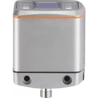
| Product type | 3D Time-of-Flight (ToF) sensor |
| Model | O3D355 |
| Brand | IFM |
| Power supply | 24 V DC via M12 8-pin connector (pins 1/3) |
| Communication interface | Ethernet (EtherNet/IP, PROFINET, TCP/IP) via M12 4-pin D-coded connector |
| Digital outputs | 3 switching outputs (PNP/NPN configurable) |
| Analog output | 1 current output (4-20 mA) or voltage (0-10 V) on pin 4 |
| Inputs | 2 switching inputs (application selection), 1 trigger input |
| Measurement principle | Time-of-Flight (ToF), infrared illumination (800-900 nm) |
| Typical applications | Completeness check, level measurement, object dimensioning, pick and place, depalletizing |
| Configuration software | ifm Vision Assistant (free) via Ethernet |
| Mounting | 2 M5 screws, optional mounting kit (E3D301), heat sink (E3D302/E3D304) |
| Maximum surface temperature | 25°C above ambient temperature (according to IEC 61010-2-201) |
| Environmental conditions | Indoor, max altitude 2000 m, relative humidity 90% max non-condensing, pollution degree 3 |
| Protection class | III (TBTP according to UL 61010-1) |
| Cleaning | Clean, lint-free cloth, glass cleaner |
| Maintenance | Firmware update via software, replace by exporting parameters |
| Certifications | EU declaration of conformity available on ifm.com |
| Required accessories | Power cable (E11950) and Ethernet cable (E11898) (not included) |
Frequently Asked Questions - O3D355 IFM
User questions about O3D355 IFM
0 question about this device. Answer the ones you know or ask your own.
Ask a new question about this device
Download the instructions for your Video camera in PDF format for free! Find your manual O3D355 - IFM and take your electronic device back in hand. On this page are published all the documents necessary for the use of your device. O3D355 by IFM.
USER MANUAL O3D355 IFM
13.1.1 Sending Commands 46
13.1.2 Receiving Images 48
13.1.3 Image data 48
13.1.4 Additional Information for CONFIDENCE IMAGE 52
13.1.5 Configuration of PCIC Output 53
13.2 Process Interface Command Reference.. 63
13.2.1 a Command (activate application) 63
13.2.2 A? Command (occupancy of application list) 63
13.2.3 c Command (upload PCIC output configuration) 64
13.2.4 C? Command (retrieve current PCIC configuration). 64
13.2.5 E? Command (request current error state). 64
13.2.6 f Command (set temporary application parameter) 65
13.2.7 G? Command (request device information) 66
13.2.8 H? Command (return a list of available commands). 67
13.2.9 I? Command (request last image taken). 68
13.2.10 o Command (set logic state of a ID) 68
13.2.11 O? Command (request state of a ID) 69
13.2.12 p Command (turn PCIC output on or off) 69
13.2.13 S? Command (request current decoding statistics) 70
13.2.14 t Command (execute asynchronous trigger). 70
13.2.15 T? Command (execute synchronous trigger) 71
13.2.16 v Command (set current protocol version) 71
13.2.17 V? Command (request current protocol version) 71
13.3 Error codes 72
13.4 EtherNet/IP 73
13.4.1 Data structures for consuming and producing assemblies 73
13.4.2 Functionality of the Ethernet/IP application 74
13.4.3 Extended commands 78
13.4.4 Signal sequence with synchronous trigger 79
13.4.5 Signal sequence with failed trigger 79
13.5 PROFINETIO. 80
13.5.1 Data structures for output and input frame 80
13.5.2 Functionality of PROFINET IO application 80
13.5.3 Extended commands 85
13.5.4 Signal sequence with synchronous trigger 85
13.5.5 Signal sequence with failed trigger 86
Copyright
Microsoft, Windows, Windows Vista, Windows 7, Windows 8, Windows 10, Windows 11, Windows 12, Windows 13, Windows 14, Windows 15, Windows 16, Windows 17, Windows 18, Windows 19, Windows 20, Windows 21, Windows 22, Windows 23, Windows 24, Windows 25, Windows 26, Windows 27, Windows 28, Windows 29, Windows 30, Windows 31, Windows 32, Windows 33, Windows 34, Windows 35, Windows 36, Windows 37, Windows 38, Windows 39, Windows 40, Windows 41, Windows 42, Windows 43, Windows 44, Windows 45, Windows 46, Windows 47, Windows 48, Windows 49, Windows 50, Windows 51, Windows 52, Windows 53, Windows 54, Windows 55, Windows 56, Windows 57, Windows 58, Windows 59, Windows 60, Windows 61, Windows 62, Windows 63, Windows 64, Windows 65, Windows 66, Windows 67, Windows 68, Windows 69, Windows 70, Windows 71, Windows 72, Windows 73, Windows 74, Windows 75, Windows 76, Windows 77, Windows 78, Windows 79, Windows 80, Windows 81, Windows 82, Windows 83, Windows 84, Windows 85, Windows 86, Windows 87,
This product can contain Free Software or Open Source Software from various software developers which is subject to the following licenses: General Public License version 1, version 2 and version 3 (General Public License version 3 in conjunction with the GNU Compiler Collection Runtime Library Exception version 3.1), Lesser General Public License version 2.1, Lesser General Public License version 3, Berkeley Software Distribution ("This product includes software developed by the University of California, Berkeley and its contributors"), The Academic Free License version 2.1. For the components subject to the General Public License in their respective versions the following applies:
This program is free software: you can redistribute it and/or modify it under the terms of the GNU General Public License as published by the Free Software Foundation. If version 1 applies to the software: either version 1 of the License or (at your option) any later version; if version 2 (or 2.1) applies to the software: either version 2 (or 2.1) of the License or (at your option) any later version; if version 3 applies to the software: either version 3 of the License or (at your option) any later version. The following disclaimer of the software developers applies to the software components that are subject to the General Public License or the Lesser General Public License in their respective versions: The Free Software is distributed in the hope that it will be useful, but WITHOUT ANY WARRANTY; without even the implied warranty of MERCHANTABILITY or FITNESS FOR A PARTICULAR PURPOSE. See the GNU General Public License and the GNU Lesser General Public License for more details.
The responsibility of ifm electronic gmbh for ifm products, in the case of product-specific software, remains unaffected by the above disclaimer. Please note that the firmware for the ifm products is in some cases provided free of charge. The price of the ifm products has then to be paid for the respective device itself (hardware) and not for the firmware. For the latest information on the license agreement for your product please visit www.ifm.com
For binaries that are licensed under any version of the GNU General Public License (GPL) or the GNU LGPL you may obtain the complete corresponding source code of the GPL software from us by sending a written request to: opensource@ifm.com or to ifm electronic gmbh Friedrichstraße 1, 45128 Essen, Germany.
We charge €30 for each request. Please write "source for product Y" in the memo line of your payment. Your request should include (i) the name of the covered binary, (ii) the name and the version number of the ifm product, (iii) your name and (iv) your return address.
This offer is valid to anyone in receipt of this information.
This offer is valid for at least three years (from the date you received the GLP/LGPL covered code).
Example: Selection application 1 application 2 application 3
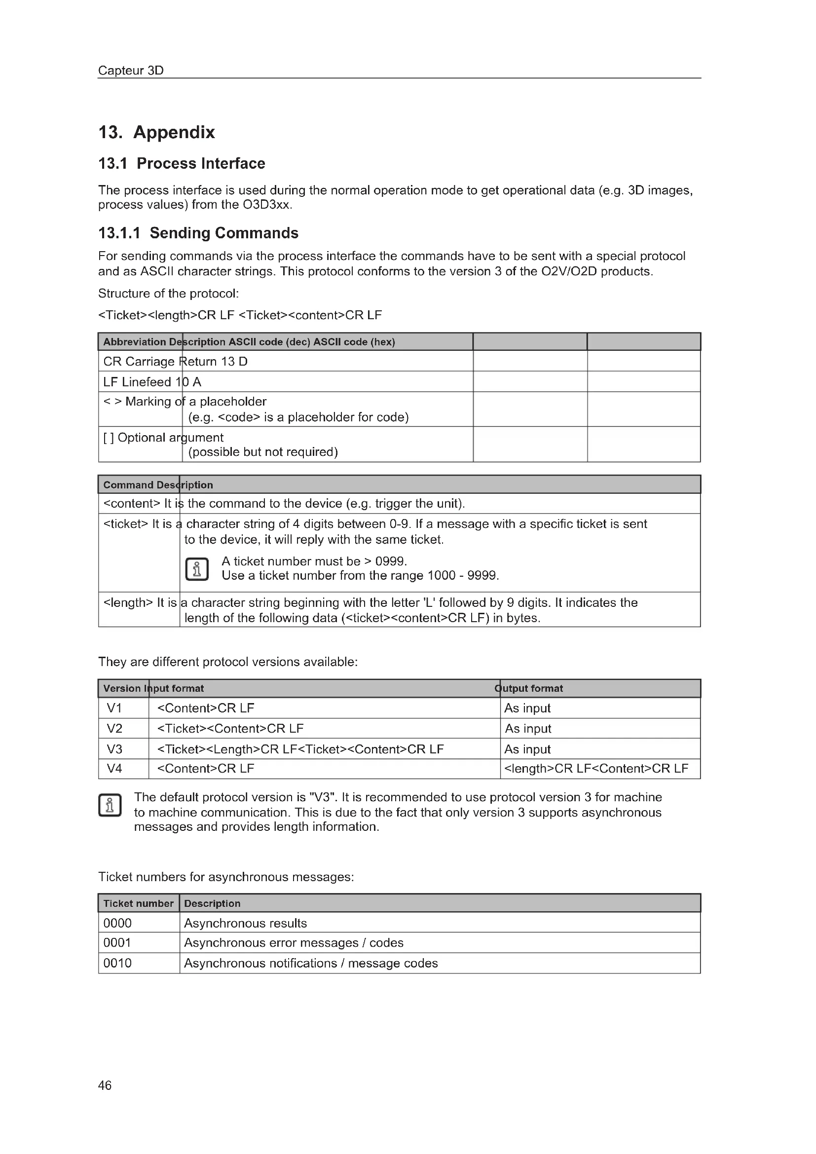
The process interface is used during the normal operation mode to get operational data (e.g. 3D images, process values) from the O3D3xx.
13.1.1 Sending Commands
For sending commands via the process interface the commands have to be sent with a special protocol and as ASCII character strings. This protocol conforms to the version 3 of the O2V/O2D products.
Structure of the protocol:
| Abbreviation Description ASCII code (dec) ASCII code (hex) | ||
| CR Carriage Return 13 D | ||
| LF Linefeed 10 A | ||
| < >Marking of a placeholder (e.g. <code> is a placeholder for code) | ||
| [ ] Optional argument (possible but not required) |
| Command Description |
| .It is the command to the device (e.g. trigger the unit). |
| .It is a character string of 4 digits between 0-9. If a message with a specific ticket is sent to the device, it will reply with the same ticket. A ticket number must be >0999. Use a ticket number from the range 1000 - 9999. |
| .It is a character string beginning with the letter 'L' followed by 9 digits. It indicates the length of the following data (<ticket><content>CR LF) in bytes. |
They are different protocol versions available:
| Version | Input format | Output format |
| V1 | As input | |
| V2 | As input | |
| V3 | As input | |
| V4 | CR LF |

The default protocol version is "V3". It is recommended to use protocol version 3 for machine to machine communication. This is due to the fact that only version 3 supports asynchronous messages and provides length information.
Ticket numbers for asynchronous messages:
| Ticket number | Description |
| 0000 | Asynchronous results |
| 0001 | Asynchronous error messages / codes |
| 0010 | Asynchronous notifications / message codes |
Format of asynchronous notifications
The format of the asynchronous notifications is a combination of the unique message ID and a JSON formatted string containing the notification details:
Example for protocol version 3:
Result:
0010L000000045\r\n001000050000:{"ID":1034160761,"Index":1,"Name": "Pos 1"}\r\n
Explanation of the result:
| Command Result | |
| <ticket=0010> 0010 | |
| L<length> L000000045 | |
| CR+LF \r\n | |
| <ticket=0010> 0010 | |
| <unique message ID> 000500000 | |
| <JSON content> {"ID": 1034160761,"Index":1,"Name": "Pos 1"} | |
| CR+LF \r\n |
Asynchronous message IDs
| Asynchronous message ID | Description Ex | Example Description | |
| 000500000 Application changed | {"ID": 1034160761,"Index":1,"Name":"Pos 1","valid":true} | ||
| 000500001 Application is not valid | {"ID": 1034160761,"Index":1,"Name":"Pos 1","valid":false} | If a application exists on given index but it is invalid, the ID and Name are filled according to the application. If there is no application on given index, the application ID will contain 0 and the name an empty string "" | |
| 000500002 image acquisition finished | {} This message signals the | reciever, that the device has finished the image acquisition. This can be used for cascading multiple devices with a software trigger. | |
13.1.2 Receiving Images
For receiving the image data a TCP/IP socket communication is established. The default port number is 50010. The port number may differ based on the configuration. After opening the socket communication, the O3D3XX device will automatically (if the device is in free run mode) send the data through this socket to the TCP/IP client (PC).
PCIC output per frame. The following data is submitted in this sequence:
| Component Content | |
| Ticket and length information (→13.2.15) | |
| Ticket "0000" | |
| Start sequence String "star" (4 bytes) | |
| Normalised amplitude image | 1 image |
| Output format: 16-bit unsigned integer | |
| Distance image | 1 image |
| Output format: 16-bit unsigned integer. | |
| Unit: mm | |
| X image | 1 image |
| Output format: 16-bit signed integer. | |
| Unit: mm | |
| Y image | 1 image |
| Output format: 16-bit signed integer. | |
| Unit: mm | |
| Z image | 1 image |
| Output format: 16-bit signed integer. | |
| Unit: mm | |
| Confidence image | 1 image |
| Output format: 8-bit unsigned integer | |
| Diagnostic data | |
| Stop sequence String "stop" (4 bytes) | |
| Ticket signature <CR><LF> |
13.1.3 Image data
For every image there will be a separate chunk. The chunk is part of the response frame data of the process interface.
The header of each chunk contains different kinds of information. This information is separated into bytes. The information contains e.g. the kind of image which will be in the "PIXEL_DATA" and the size of the chunk.
| Offset Name | Description Size [byte] | ||
| 0x0000 | CHUNK_TYPE Defines the type of the chunk. For each distinct chunk an own type is defined. | 4 | |
| 0x0004 | CHUNK_SIZE Size of the whole image chunk in bytes. After this count of bytes the next chunk starts. | 4 | |
| 0x0008 | ADER_SIZE Number of bytes starting from 0x0000 until Pixel_DATA. | 4 | |
| 0x000C | HEADER_VERSION | Version number of the header | 4 |
| 0x0010 | IMAGE_WIDTH | Image width in pixel 4 | |
| 0x0014 | IMAGE_HEIGHT | Image height in pixel 4 | |
| 0x0018 | PIXEL_FORMAT Pixel format | at 4 | |
| 0x001C | TIME_STAMP Time stamp | in microseconds (deprecated) 4 | |
| 0x0020 | FRAME_COUNT Frame counter 4 | ||
| 0x0024 | STATUS_CODE Errors of the device 4 | ||
| 0x0028 | TIME_STAMP_SEC Time stamp in seconds | 4 | |
| 0x002C | TIME_STAMP_NSEC Time stamp in nanoseconds | 4 | |
| 0x0030 | PIXEL_DATA The pixel data in the given type and dimension of the image. Padded to 4-byte boundary. | 4 | |
Available chunk types:
| Constant | Value | Description |
| RADIAL_distance_IMAGE | 100 | Each pixel of the distance matrix denotes the ToF distance measured by the corresponding pixel or group of pixels of the imager. The distance value is corrected by multipath and multiple objects contributions (e.g. "flying pixels"). Reference point is the optical centre of the camera inside the camera housing.Invalid PMD pixels (e.g. due to saturation) have a value of zero.Data type: 16-bit unsigned integer (little endian)Unit: millimetres |
| NORM_AMPLITU卖家 | 101 | Each pixel of the normalized amplitude image denotes the raw amplitude (see amplitude image below for further explanation), normalized to exposure time. Furthermore, vignetting effects are compensated, ie the darkening of pixels at the image border is corrected. The visual impression of this grayscale image is comparable to that of a common 2D camera.Invalid PMD pixels (e.g. due to saturation) have an amplitude value of 0.Data type: 16-bit unsigned integer |
| AMPLITUDE_IMAGE | 103 | Each pixel of the amplitude matrix denotes the amount of modulated light (i.e. the light from the camera's active illumination) which is reflected by the appropriate object. Higher values indicate higher PMD signal strengths and thus a lower amount of noise on the corresponding distance measurements. The amplitude value is directly derived from the PMD phase measurements without normalisation to exposure time. In multiple exposure mode, the lack of normalisation may lead (depending on the chosen exposure times) to inhomogeneous amplitude image impression, if a certain pixel is taken from the short exposure time and some of its neighbours are not.Invalid PMD pixels (e.g. due to saturation) have an amplitude value of 0.Data type: 16-bit unsigned integer |
| GRAYSCALE_IMAGE | 104 | Each pixel of the amplitude matrix denotes the amount of modulated light which is reflected by the appropriate object (i.e. the light from the camera's active illumination). Higher values indicate higher PMD signal strengths and thus a lower amount of noise on the corresponding distance measurements. The amplitude value is directly derived from the PMD phase measurements without normalisation to exposure time. |
| Constant Value Description | ||
| CARTESIAN_X Component | 200 The X matrix denotes the X component of the Cartesian coordinate of a PMD 3D measurement. The origin of the camera's coordinate system is in the middle of the lens' front glass, if the extrinsic parameters are all set to 0.Data type: 16-bit signed integerUnit: millimetres | |
| CARTESIAN_Y Component | 201 The Y matrix denotes the Y component of the Cartesian coordinate of a PMD 3D measurement. The origin of the camera's coordinate system is in the middle of the lens' front glass, if the extrinsic parameters are all set to 0.Data type: 16-bit signed integerUnit: millimetres | |
| CARTESIAN_Z Component | 202 The Z matrix denotes the Z component of the Cartesian coordinate of a PMD 3D measurement. The origin of the camera's coordinate system is in the middle of the lens' front glass, if the extrinsic parameters are all set to 0.Data type: 16-bit signed integerUnit: millimetres | |
| CARTESIAN_ALL 203 CARTESIAN | X_COMPONENT, CARTESIAN_Y_COMPONENT, CARTESIAN_Z_COMPONENT | |
| UNIT_VECTOR_ALL 223 | The unit vector matrix contains 3 values [ex, ey, ez] for each PMD pixel, i.e. the data layout is [ex_1,ey_1,ez_1,... ex_N,ey_N, ez_N], where N is the number of PMD pixels.Data type: 32-bit floating point number (3x per pixel) | |
| CONFIDENCE_IMAGE | See Additional Information for Image Data (→13.1.4) | |
| DIAGNOSTIC 302 See Receiving Images (→13.1.2) | ||
| JSON_DIAGNOSTIC 305 | Items with JSON formatted diagnostic data is formatted like this:{"AcquisitionDuration": 20.391, "EvaluationDuration": 37.728, "FrameDuration": 37.728, "FrameRate": 15.202, "TemperatureIllum": 52.9}Unit for durations: millimetresUnit for framereates: HzUnit for temperature: °C | |
| EXTRINSIC_CALIB 400 | The transformation from one cartesian coordinate system to another is defined by a 6 degrees of freedom vector (DOF): [trans_x, trans_y, trans_z, rot_x, rot_y, rot_z]. Let R be the product of the common "clockwise" 3D-rotation matrices: R = Rx*Ry*RzThe transformation of a point P is specified by P_t = R*P + [trans_x, trans_y, trans_z']. The device extrinsic calibration can be set by the user, but it may be changed by an automatic calibration feature of the device. Data type: 32-bit floating point number (little endian) Unit for trans_x, trans_y, trans_z: millimetres Unit for rot_x, rot_y, rot_z: ° | |
| JSON_MODEL 500 Model | data in JSON | |
| MODEL_ROIMASK 501 | ROI mask for internal debugging purposes | |
| SNAPSHOT_IMAGE 600 | Snapshot | image |
Pixel format:
| Constant Value Description | ||
| FORMAT_8U 0 8-bit unsigned integer | ||
| FORMAT_8S 1 8-bit signed integer | ||
| FORMAT_16U 2 16-bit unsigned integer | ||
| FORMAT_16S 3 16-bit signed integer | ||
| FORMAT_32U 4 32-bit unsigned integer | ||
| FORMAT_32S 5 32-bit signed integer | ||
| FORMAT_32F 6 32-bit floating point number | ||
| FORMAT_64U 7 64-bit unsigned integer | ||
| FORMAT_64F 8 64-bit floating point number | ||
| Reserved | 9 N/A | |
| FORMAT_32F_3 10 | Vector with 3x32-bit floating point number | |
13.1.4 Additional Information for CONFIDENCE_IMAGE
Further information for the confidence image:
| Bit Value Description | ||
| 0 1 = pixel invalid Pixel invalid | The pixel is invalid. To determine whether a pixel is valid or not only this bit needs to be checked. The reason why the bit is invalid is recorded in the other confidence bits. | |
| 1 1 = pixel saturated Pixel is saturated | Contributes to pixel validity: yes | |
| 2 1 = bad A-B symmetry A-B pixel symmetry | The A-B symmetry value of the four phase measurements is above threshold.Remark: This symmetry value is used to detect motion artefacts. Noise (e.g. due to strong ambient light or very short integration times) or PMD interference may also contribute.Contributes to pixel validity: yes | |
| 3 1 = amplitude below minimum amplitude threshold | Amplitude limitsThe amplitude value is below minimum amplitude threshold.Contributes to pixel validity: yes | |
| 4+5 Bit 5, bit 40 0 0 = unused0 1 = shortest exposure time (only used in 3 exposure mode)1 0 = middle exposure time in 3 exposure mode, short exposure in double exposure mode1 1 = longest exposure time (always 1 in single exposure mode) | Exposure time indicatorThe two bits indicate which exposure time was used in a multiple exposure measurement.Contributes to pixel validity: no | |
| 6 1 = pixel is clipped Clipping box on 3D dataIf clipping is active this bit indicates that the pixel coordinates are outside the defined volume.Contributes to pixel validity: yes | ||
| 7 1 = suspect/defective pixel Suspect pixelThis pixel has been marked as "suspect" or "defective" and values have been replaced by interpolated values from the surroundings.Contributes to pixel validity: no | ||
13.1.5 Configuration of PCIC Output
The user has the possibility to define his own PCIC output. This configuration is only valid for the current PCIC connection. It does not affect any other connection and will get lost after disconnecting.
For configuring the PCIC output a "flexible" layouter concept is used, represented by a JSON string. The format of the default configuration is as follows:
{
    "layouter": "flexible",
    "format": { "dataencoding": "ascii" },
    "elements": [
        { "type": "string", "value": "star", "id": "start_string" },
        { "type": "blob", "id": "normalized_amplitude_image" },
        { "type": "blob", "id": "x_image" },
        { "type": "blob", "id": "y_image" },
        { "type": "blob", "id": "z_image" },
        { "type": "blob", "id": "confidence_image" },
        { "type": "blob", "id": "diagnostic_data" },
        { "type": "string", "value": "stop", "id": "end_string" }
    ]
}
This string can be retrieved by the C? command, altered and sent back using the c command.
The layout software has the following main object properties:
| Name Description | Details | |
| layouter Defines the basic data output format. So far only "flexible" is supported | Type: string | |
| format Defines format details, the definitions in the main object are the defaults for any of the following data elements (e.g. if it says dataencoding=binary, all data elements should be binary encoded instead of ASCII). | Type: object | |
| elements List of data elements which must be written. Type: array of objects | ||
The actual data is defined within the "elements" properties and may consist of these settings:
| Name Description Details | ||
| type Defines the type of data which must be written. The data might be stored in a different type (e.g. stored as integer but should be output as Float32) The type "records" will need some special handling. | Type: string | |
| id Defines an identifier for this data element. If there is no fixed value (property "value"), the data should be retrieved via id. | Type: string | |
| value Optional property for defining a fixed output value. Type: any JSON value | ||
| format Type-dependent option for fine-tuning the output format. E.g. cut an integer to less than 4 bytes. | Type: object | |
Available values for the type property:
| Type Description | on |
| records Defines that this element represents a list of records. If type is set to "records", there must be an "elements" property. The "elements" property defines which data should be written per record. | |
| string Data is written as string. Most of the time this will be used with "value" property to write fixed start, end or delimiter text. Text encoding should be UTF8 if there is nothing else specified in format properties. | |
| float32 Data is written as floating point number. This has a lot of formatting options (at least with "flexible" layout software) See following section about format properties. | |
| uint32 Data is written as integer. This has a lot of formatting options (at least with "flexible" layout software) See following section about format properties. | |
| int32 Data is written as integer. This has a lot of formatting options (at least with "flexible" layout software) See following section about format properties. | |
| uint16 Limits the output to two bytes in binary encoding, besides the binary limitation it acts like uint32. | |
| int16 Limits the output to two bytes in binary encoding, besides the binary limitation it acts like int32. | |
| uint8 Limits the output to one byte in binary encoding, besides the binary limitation it acts like uint32. | |
| int8 Limits the output to one byte in binary encoding, besides the binary limitation it acts like int32. | |
| blob Data is written as a BLOB (byte by byte as if it came from the data provider). (Binary Large Object) | |
Depending on the desired data format the user may tune his output data with further "format" properties.
Common format properties:
| Format properties | Allowed values Default | |
| dataencoding "ascii" or "binary" can be defined in top-level-object and overwritten by element objects. | "ascii" | |
| scale "float value with decimal separator" to scale the results for output byte width | 1.0 | |
| offset "float value with decimal separator" 0.0 | ||
Binary format properties:
| Format properties | Allowed values Default | |
| order | Little, big and network | Little |
ASCII format properties:
| Format properties Allowed | wed values Default | |
| width Output width. | If the resulting value exceeds the width field the result will not be truncated. | 0 |
| fill Fill character " " | ||
| precision Precision | is the number of digits behind the decimalseparated. 6 | |
| displayformat Fixed, scientific Fixed | ||
| alignment Left, right Right | ||
| decimalseparated 7-bit characters for e.g. ".". ." | ||
| base Defines if the | output should be: • binary (2) • octal (8) • decimal (10) • hexadecimal (16) | 10 |
Example of a format configuration of the temperature (id: temp_illu) element.
- Illumination temperature like this "33,5":
c000000226 {"layouter": "flexible", "format": {"dataencoding": "ascii"}, "elements": [ {"type": "float32", "id": "temp_illu", "format": {"width": 7, "precision": 1, "fill": "_", "alignment": "left", "decimalseparator": "","] } ]
- Illumination temperature as binary (16-bit integer, 1 / 10^ ):
c000000194{ "layouter": "flexible", "format": {"dataencoding": "ascii"}, "elements": [ { "type": "int16", "id": "temp_illu", "format": {"dataencoding": "binary", "order": "network", "scale": 10} ] ] }
- Illumination temperature in ^ F (e.g. "92.3 Fahrenheit"):
c000000227{"layouter":"flexible","format": {"dataencoding":"ascii"}, "elements": ["type":"float32","id":"temp_illu","format": {"precision": 1, "scale": 1.8, "offset": 32}], {"type": "string", "value": "Fahrenheit"] } ]

The following element IDs are available:
| ID Description Native data type | ||
| activeapp_id Active application, shows which of the 32 application-configurations is currently active | 32-bit unsigned integer | |
| all_caresian_vector_matrices | All Cartesian images (X+Y+Z) concatenated to one package | 16-bit signed integer |
| all_unit_vector_matrices | Matrix of unit vectors. Each element consists of a 3 component vector [e_x, e_y, e_z] | Float32 |
| amplitude_image PMD raw amplitude image 16-bit unsigned | integer | |
| confidence_image Confidence image 8-bit unsigned | integer | |
| distance_image Radial distance image 16-bit unsigned | integer unit: millimetres | |
| evaltime Evaluation time for current frame in milliseconds 32-bit unsigned | integer | |
| extrinsic Calibration Extrinsic calibration, consisting of 3 translation parameters (unit: millimeters) and 3 angles (unit: degree): [t_x, t_y, t_z, alpha_x, alpha_y, alpha_z] | Float32 | |
| framerate Current frame rate in Hz Float32 | ||
| normalized_amplitude_image | Normalized amplitude image | 16-bit unsigned integer |
| temp_front1 | Invalid temperature, the output is 3276.7 | Float32, unit: °C |
| temp_illu | Temperature measured in the device while capturing this result Measured on the illumination board | Float32, unit: °C |
| x_image | Cartesian coordinates for each pixel | 16-bit signed integer |
| y_image | Each dimension is a separate image | |
| z_image |
For completeness, level, distance and dimensioning application the following IDs are available:
| ID Description Native data type | ||
| id ID of the model int32 | ||
| rois.count Number of records in "roi" int32 | ||
| rois.List of all ROIs (ROIgroup) of this model records | ||
| SP1 | SwitchingPoint1 and 2 if the model is a Level- or Distance-type. If it is not a Level-/Distance-type, it shall output a null-value. | float32 |
| SP2 | ||
| boxFound | These results are available for a dimensioning application. If the model is not oft the type dimensioning, the IDs shall output a null-value. | int8 |
| length | float | |
| width | float | |
| height | float | |
| qualityLength | float | |
| qualityWidth | float | |
| qualityHeight | float | |
| xMidTop | float | |
| yMidTop | float | |
| zMidTop | float | |
| yawAngle | float | |
| backgroundPlaneDistance | float | |
| numGood | These results are available for a completeness, level and distance applications. If the model is not oft one of these types, the IDs shall output a null-value. | int |
| numUnderSP1 | int | |
| numOverSP2 | int | |
| numInvalid | int | |
| allROIsGood | bool | |
| anchorFound | bool | |
| hasAnchorTracking | bool |
For ROIs of completeness, level or distance application the following IDs are available:
| ID Description | Native data type | |
| id unique | ID of the ROI within the Model int32 | |
| procval per ROI process value float 32Bit | ||
| state per ROI state ( if ROI procval is valid or not) | uint32 | |
| • ROI_PROCESS_VALUE_VALID = 0 • ROI_PROCESS_VALUE_REFIMAGE_SET_NOT_SECHED = 1 • ROI_PROCESS_VALUE_SEACHING_FAILED = 2 • ROI_PROCESS_VALUE_REFIMAGE_INVALID = 3 • ROI_PROCESS_VALUE_NO_VALID_PIXEL = 4 • ROI_PROCESS_VALUE_REFIMAGE_NO_VALID_PIXEL = 5 • ROI_PROCESS_VALUE_OVERFILL = 6 • ROI_PROCESS_VALUE UNDERFILL = 7 | ||
| quality | 0..1 | float32 |
For the main object on devices with statistics feature the following IDs are available:
| ID Description Native data type | ||
| statistics_overall_count Allows the | user to output the statistics value with the result of the frame, maps to ModelResults: adv_statistics.number_of Frames | uint32 |
| statistics Passed_count Allows the | user to output the statistics value with the result of the frame, maps to ModelResults: adv_statistics.number_of Passed Frames | uint32 |
| statistics_failed_count Allows the | user to output the statistics value with the result of the frame, maps to ModelResults: adv_statistics.number_of_FAILEDFrames | uint32 |
| statistics_aborted_count Allows the | user to output the statistics value with the result of the frame, maps to ModelResults: adv_statistics.number_of_abortedFrames | uint32 |
| statistics Acquisition_time_min Allows the | allows the user to output the statistics value with the result of the frame,maps to ModelResults: adv_statistics.frame_acquisition.min | float32 |
| statistics Acquisition_time_mean Allows the | allows the user to output the statistics value with the result of the frame,maps to ModelResults: adv_statistics.frame_acquisition.mean | float32 |
| statistics Acquisition_time_max Allows the | allows the user to output the statistics value with the result of the frame,maps to ModelResults: adv_statistics.frame_acquisition.max | float32 |
| statistics_evaluation_time_min Allows the | allows the user to output the statistics value with the result of the frame,maps to ModelResults: adv_statistics.frame_evaluation.min | float32 |
| statistics_evaluation_time_mean Allows the | allows the user to output the statistics value with the result of the frame,maps to ModelResults: adv_statistics.frame_evaluation.mean | float32 |
| statistics_evaluation_time_max Allows the | allows the user to output the statistics value with the result of the frame,maps to ModelResults: adv_statistics.frame_evaluation.max | float32 |
| statistics_frame_duration_min Allows the | allows the user to output the statistics value with the result of the frame,maps to ModelResults: adv_statistics.frame_duration.min | float32 |
| statistics_frame_duration_mean Allows the | allows the user to output the statistics value with the result of the frame,maps to ModelResults: adv_statistics.frame_duration.mean | float32 |
| statistics_frame_duration_max Allows the | allows the user to output the statistics value with the result of the frame,maps to ModelResults: adv_statistics.frame_duration.max | float32 |
For model records of type "DimensioningV2" (Robot Pick & Place) the following IDs are available:

Length values are given in unit [m].
Rotation values are given in unit [^] .
| ID Description Native | data type | |
| numberOfObjects Number of found objects. uint32 | ||
| numberOfObjectCandidates Number of found object candidates that have been inspected. | uint32 | |
| error Dimensioning error: | 0: no error1: undefined error2: no object found | uint32 |
| maximumNumberOfObjectsTo Measure | Maximum number of objects to measure. uint32 | |
| objectGeometry Geometry type | of object:0: Box1: Circle2: Ellipse | uint32 |
| objects[maximumNumberOfObjectsToMeasure] | This structure is provided for each object defined by maximumNumberOfObjectsToMeasure. If not all objects have been found, the values are also provided for the number of missing objects. | |
| { | Object can be successfully measured (0 if false, 1 if true). | uint32 |
| objectFound | Object length is the longest dimension of the object. | float32 |
| length | Object width is the shortest dimension of the object. | float32 |
| width | Object height is the object height relative to the ground plane. | float32 |
| height | Cartesian X coordinates of middle point on the top surface of the detected object. | float32 |
| xMidTop | Cartesian Y coordinates of middle point on the top surface of the detected object. | float32 |
| yMidTop | Cartesian Z coordinates of middle point on the top surface of the detected object. | float32 |
| zMidTop | Cartesian Z coordinates of middle point on the top surface of the detected object. | float32 |
| yawAngle | Yaw angle is defined as the angle between the world coordinate x-axis and the vector along the object "length". | float32 |
| circleThickness | The thickness of the circle. | float32 |
| centerPointX | X coordinate of the top center point from the detected object (user frame coordinate system). | float32 |
| centerPointY | Y coordinate of the top center point from the detected object (user frame coordinate system). | float32 |
| centerPointZ | Z coordinate of the top center point from the detected object (user frame coordinate system). | float32 |
| rotationX | X rotation of the detected object (user frame coordinate system). | float32 |
| rotationY | Y rotation of the detected object (user frame coordinate system). | float32 |
| rotationZ | Z rotation of the detected object (user frame coordinate system). | float32 |
| For compatibility reasons the following values are provided for the first detected object. | ||
| boxFound | Object can be successfully measured (0 if false, 1 if true). | uint32 |
| length | Object length is the longest dimension of the object. | float32 |
| width | Object width is the shortest dimension of the object. | float32 |
| height | Object height is the object height relative to the ground plane. | float32 |
| xMidTop | Cartesian X coordinates of middle point on the top surface of the detected object. | float32 |
| yMidTop | Cartesian Y coordinates of middle point on the top surface of the detected object. | float32 |
| zMidTop | Cartesian Z coordinates of middle point on the top surface of the detected object. | float32 |
| yawAngle | Yaw angle is defined as the angle between the world coordinate x-axis and the vector along the object "length". | float32 |
| circleThickness | The thickness of the circle. | float32 |
| centerPointX | X coordinate of the top center point from the detected object (user frame coordinate system). | float32 |
| centerPointY | Y coordinate of the top center point from the detected object (user frame coordinate system). | float32 |
| centerPointZ | Z coordinate of the top center point from the detected object (user frame coordinate system). | float32 |
| rotationX | X rotation of the detected object (user frame coordinate system). | float32 |
| rotationY | Y rotation of the detected object (user frame coordinate system). | float32 |
| rotationZ | Z rotation of the detected object (user frame coordinate system). | float32 |
| backgroundPlaneDistance | Distance of the background at background teach. | float32 |
| objectType | Type of the detected object: 1: box 2: true bounding box 3: circle 4: enclosing circle 5: ellipse 6: enclosing ellipse | uint32 |
| UFCThreeMarkerTeach["A"..."C"] | Coordinates of the available UFC markers. | |
| {x} | float32 | |
| y} | float32 |
For model records of type "Depalletizing" the following IDs are available:

Length values are given in unit [m].
Rotation values are given in unit [^ ]
| ID Description Native | data type | ||
| error Errors in | the algorithm: | uint32 | |
| Value Name Description | |||
| 0 Depalletizing_Error_None No error detected. | |||
| 1 Depalletizing_Error_Unknown Unknown error detected. | |||
| 2 Depalletizing_Error_UnexpectedObject | Unexpected object detected. | ||
| 3 Depalletizing_Error_DStackEmpty Stack is empty. | |||
| 4 Depalletizing_Error_NoObjectSizes No box dimensions provided on the input. | |||
| 5 Depalletizing_Error_NoObjectMatch No matching object found. | |||
| 6 Depalletizing_Error_Datalimit Too many pixels are invalid. | |||
| 7 Depalletizing_Error_Background TeachingStatus_ErrorNot EnoughValidPixels | Background estimation only: not enough valid pixels. | ||
| 8 Depalletizing_Error_Background TeachingStatus_ErrorStdTooHigh | Background estimation only: standard deviation too high. | ||
| 9 Depalletizing_Error_Background TeachingStatus_ErrorPlaneFail failed | Background estimation only: estimation of the plane failed. | ||
| 10 Depalletizing_Error_Background TeachingStatus_ErrorPlane AngleTooHigh | Background estimation only: plane angle too high. | ||
| 11 Depalletizing_Error_Background TeachingStatus_ErrorRotation CalculationFailed | Background estimation only: internal numerical error in calculation of rotation. | ||
| 12 Depalletizing_Error_InvalidReferenceTeach | Invalid background teach. | ||
| 13 Depalletizing_Error_InvalidVOITeach | Invalid VOI teach. | ||
| 14 Depalletizing_Error_Insufficient MarginToImageBorder | Not enough space between segmented layer and image border. | ||
| 15 Depalletizing_Error_IncorrectObjectSizes | Provided box dimensions are invalid. | ||
| 16 Depalletizing_Error_Underfill Measurements are below the background level. | |||
| objectFound | Object can be successfully measured (0 if false, 1 if true). | uint32 | |
| objectQuality | Quality of the object detection between 0 and 100. | float32 | |
| objectLength | Object length is the longest dimension of the top surface of the object. | float32 | |
| objectWidth | Object width is the shortest dimension of the top surface of the object. | float32 | |
| objectHeight | Object height is the object height relative to the ground plane. | float32 | |
| centerPointX | X coordinate of the top center point from the detected object (user frame coordinate system). | float32 | |
| centerPointY | Y coordinate of the top center point from the detected object (user frame coordinate system). | float32 | |
| centerPointZ | Z coordinate of the top center point from the detected object (user frame coordinate system). | float32 | |
| rotationX | X rotation of the detected object (user frame coordinate system). | float32 | |
| rotationY | Y rotation of the detected object (user frame coordinate system). | float32 | |
| ID Description Native | data type | |
| rotationZ Z rotation of the detected object (user frame coordinate system). float32 | ||
| layerLevel | Current pallet layer for depalletization, starting with "0". An empty stack is indicated by "0". | uint32 |
| sensorMountingHeight | Recommended height of the sensor above the palette.Values "<=0": invalid input parameters (e.g. invalid palette dimensions). | float32 |
| isSlipSheet A | slipsheet is on top of the stack:0: no1: yes | uint32 |
| background PlaneDistance | Distance of the background plane in positive direction of the z-axis. float32 | |
| isCollisionFree | Collision free depalletization:0: false1: true | uint32 |
| centerPoint2DX | The top center X coordinate of the detected box object (projected into the 2D image). | float32 |
| centerPoint2DY | The top center Y coordinate of the detected box object (projected into the 2D image). | float32 |
The following IDs can be changed with the f command ( 13.2.6)
| ID Name Description | Values | ||
| 0000000001 | DepalSlipSheetDetection Depalletizing: slip sheet detection on/off | 1/0 | |
| 0000000002 | DepalSlipObjectType Depalletizing: type of the object to be detected | 0: box 1: bag | |
| 0000000003 | DepalWidth Depalletizing: width of the objects to be detected | mm | |
| 0000000004 | DepalHeight Depalletizing: length of the objects to be detected | mm | |
| 0000000005 | DepalLength Depalletizing: heigth of the objects to be detected | mm |
13.2 Process Interface Command Reference

All received messages which are sent because of the following commands will be sent without "start"/"stop" at the beginning or ending of the string.
13.2.1 a Command (activate application)
| Command | a<application number> | |
| Description Activates the selected | application | |
| Type Action | ||
| Reply * | ||
| ! · Application not available | · <application number> contains wrong value · External application switching activated · Device is in an invalid state for this command, e.g. configuration mode | |
| ? Invalid command length | ||
| Note <application number> | 2 digits for the application number as decimal value |
13.2.2 A? Command (occupancy of application list)
| Command | A? | |
| Description Requests the occupancy of the application list | ||
| Type Request | ||
| Reply <amount><t><number active>application><t>...<number><t><number> | ? Invalid command length | |
| ! Invalid state (e.g. no application active) | ||
| Note <amount>char string with 3 digits for the amount of applications saved on the device as decimal number <t>tabulator (0x09)<number active application>2 digits for the active application <number>2 digits for the application number | The active application is repeated within the application list. | |
13.2.3 c Command (upload PCIC output configuration)
| Command | c<length><configuration> | |
| Description Uploads a PCIC output | configuration lasting this session | |
| Type Action | ||
| Reply* | ||
| ! • Error in configuration | Wrong data length | |
| ? Invalid command length | ||
| Note <length> | 9 digits as decimal value for the data length | |
| <configuration> | ||
| configuration data |
13.2.4 C? Command (retrieve current PCIC configuration)
| Command | C? | |
| Description Retrieves the current PCIC configuration | ||
| Type Request | ||
| Reply <length><configuration> | ||
| ? Invalid command length | ||
| Note <length> | 9 digits as decimal value for the data length | |
| <configuration> | ||
| configuration data | ||
13.2.5 E? Command (request current error state)
| Command | E? | |
| Description Requests the current error state | ||
| Type Request | ||
| Reply <code> | ||
| ! Invalid state (e.g. configuration mode) | ||
| ? Invalid command length | ||
| Note • <code> | Error code with 8 digits as a decimal value. It contains leading zeros. | |
13.2.6 f Command (set temporary application parameter)
| Command | f<Parameter-ID><reserved><value> | |
| Description Set temporary application parameter | ||
| <Parameter-id> Id of parameter to be setFixed 5 bytes decimal ASCII padded with "0", e.g. "00003". | ||
| <reserved> Fixed to "#00000" | ||
| <value> Fixed 5 bytes signed decimal ASCII padded with "0" and sign, e.g. "+00777" | ||
| Type Action | ||
| Reply * Parameter successfully set | ||
| ! Parameter-id invalid or syntax error | ||
| ? Invalid command length | ||
| Note Example: | f00003#00000+00777 | |
13.2.7 G? Command (request device information)
| Command | G? | ||
| Description Requests device information | |||
| Type Request | |||
| Reply <vendor><t><article numbe>><t><name><t><location><t><description><t></ip><sub>,<sub>subnet mask></t></sub>><gateway><t><MAC><t><DHCP><t><port number> | |||
| Note • <vendor> | IFM ELECTRONICTabulator (0x09)e.g. O3D300<name>UTF8 Unicode string<location>UTF8 Unicode string<description>UTF8 Unicode string<ip>IP address of the device as ASCII character stinge.g. 192.168.0.96<sub>,<sub>port number></sub>port number of the XML-RPC<sub>,<sub>,<sub>,<sub>,<sub>,<sub>port number></sub>port number of the device as ASCII e.g. 192.168.0.96<sub>,<sub>,<sub>,<sub>,<sub>,<sub>,<sub>port number></sub>port number of the device as ASCII e.g. 192.168.0.96<sub>,<sub>,<sub>,<sub>,<sub>,<sub>,<sub>port number></sub>port number of the device as ASCII e.g. AA:AA:AA:AA:AA<sub>,<mac>MAC adress of the device as ASCII e.g. AA:AA:AA:AA:AA<sub>,<DHCP>ASCII string "0" for off and "1" for on | ||
13.2.8 H? Command (return a list of available commands)
| Command | H? | |
| Description Returns a list of available commands | ||
| Type Request | ||
| Reply H? - show this list | t - execute TriggerT? - execute Trigger and wait for datao<io-id><io-state> - sets IO stateO<io-id>? - get IO stateI<img-id>? - get last image of defined typeA? - get application listp<state> - activate / deactivate data outputa<application number> - set active applicationE? - get last errorV? - get current protocol versionv<version> - sets protocol versionc<length of configurationfile><configuration file> - configures process date formattingC? - show current configurationG? - show device informationS? - show statisticsL? - retrieves the connection IDf<id><reserved><value> - set parameter value | |
13.2.9 I? Command (request last image taken)
| Command | I<image-ID>? | ||
| Description Request last image taken | |||
| Type Request | |||
| Reply <length><image data> | |||
| ! • No image available | Wrong ID | ||
| ? • Invalid command length | |||
| Note <image-ID> | 2 digits for the image type | Valid image ID:01 - amplitude image02 - normalised amplitude image03 - distance image04 - X image (distance information)05 - Y image (distance information)06 - Z image (distance information)07 - confidence image (status information)08 - extrinsic calibration09 - unit_vector_matrix_ex, ey,ez10 - last result output as formatted for this connection11 - all distance images: X, Y, and Z | |
| <length> | |||
| char string with exactly 9 digits as decimal number for the image data size in bytes | |||
| <image data> | |||
| image data | |||
13.2.10 o Command (set logic state of a ID)
| Command | oIO-ID><IO-state> | |
| Description Sets the logic state of a specific ID | ||
| Type Action | ||
| Reply* | ||
| ! Invalid state (e.g. configuration mode) | ||
| ? | Invalid command length | |
| Note | ·<IO-ID> 2 digits for digital output: "01" for IO1 "02" for IO2 "03" for IO3 ·<IO-state> 1 digit for the state: "0" for logic state low "1" for logic state high | |
13.2.11 O? Command (request state of a ID)
| Command | O<IO-ID>? | |
| Description Requests the state of a specific ID | ||
| Type Request | ||
| Reply<I0-ID><IO-state> | ||
| ! · Invalid state (e.g. configuration mode) · Wrong ID | ||
| ? Invalid command length | ||
| Note · <IO-ID> | 2 digits for digital output: "01" for IO1 "02" for IO2 "03" for IO3 · <IO-state> 1 digit for the state: "0" for logic state low "1" for logic state high | The camera supports ID 1 and ID 2. The sensor supports ID 1, ID 2 and ID 3. |
13.2.12 p Command (turn PCIC output on or off)
| Command | p<state> | |
| Description Turns the PCIC output on or off | ||
| Type Action | ||
| Reply* | ||
| ! <state> contains wrong value | ||
| ? Invalid command length | ||
| Note | <state> 1 digit0: deactivates all asynchronous output1: activates asynchronous result output2: activates asynchronous error output3: activates asynchronous error and data output4: activates asynchronous notifications5: activates asynchronous notifications and asynchronous result6: activates asynchronous notifications and asynchronous error output7: activates all outputs | On device restart the value configured within the application is essential for the output of data.This command can be executed in any device state.By default the error codes will not be provided by the device. |
13.2.13 S? Command (request current decoding statistics)
| Command | S? | |
| Description Requests current decoding statistics | ||
| Type Request | ||
| Reply <number of | results><t><number of positive decodings><t><number of false decodings> | |
| ! No application active | ||
| Note <t> | tabulator (0x09) Images taken since application start. 10 digits decimal value with leading 0s <number of positive decodings> Number of decodings leading to a positive result. 10 digits decimal value with leading 0s <number of false decodings> Number of decodings leading to a negative result. 10 digits decimal value with leading 0s | |
13.2.14 t Command (execute asynchronous trigger)
| Command | t | |
| Description | Executes trigger. The result data is send asynchronously | |
| Type Action | ||
| Reply * Trigger | was executed, the | device captures an image and evaluates the result. |
| ! • Device is busy with an | evaluation • Device is in an invalid state for this command, e.g. configuration mode • Device is set to a different trigger source • No active application |
13.2.15 T? Command (execute synchronous trigger)
| Command | T? | |
| Description | Executes trigger. The result data is send synchronously | |
| Type Request | ||
| Reply Process data within the configured layout Trigger was executed, the device captures an image, evaluates the result and sends the process data. | ||
| ! • Device is busy with an | evaluation • Device is in an invalid state for this command, e.g. configuration mode • Device is set to a different trigger source • No active application | |
| Note Result | data can be sent via EtherNet/IP, PROFINET or TCP/IP (→9.3). | |
13.2.16 v Command (set current protocol version)
| Command | v<version> | |
| Description Sets the current protocol version. The device configuration is not affected | ||
| Type Action | ||
| Reply * | ||
| ! Invalid version | ||
| ? Invalid command length | ||
| Note | <version>2 digits for the protocol version | (→13.1.1) |

The default protocol version is "V3".
13.2.17 V? Command (request current protocol version)
| Command | V? | |
| Description Requests current protocol | version | |
| Type Request | ||
| Reply <current version><empty><min version><empty><max version> | ||
| Note | <current version>2 digits for the currently set version<empty>space sign: 0x20<min/max version>2 digits for the available min and max version that can be set |
13.3 Error codes
By default the error codes will not be provided by the device. The p command can activate their provision ( 13.2.12) .
| Error code ID Description |
| 100000001 Maximum number of connections exceeded |
| 110001001 Boot timeout |
| 110001002 Fatal software error |
| 110001003 Unknown hardware |
| 110001006 Trigger overrun |
| 110002000 Short circuit on Ready for Trigger |
| 110002001 Short circuit on OUT1 |
| 110002002 Short circuit on OUT2 |
| 110002003 Reverse feeding |
| 110003000 Vied overvoltage |
| 110003001 Vied undervoltage |
| 110003002 Vmod overvoltage |
| 110003003 Vmod undervoltage |
| 110003004 Mainboard overvoltage |
| 110003005 Mainboard undervoltage |
| 110003006 Supply overvoltage |
| 110003007 Supply undervoltage |
| 110003008 VFEMon alarm |
| 110003009 PMIC supply alarm |
| 110004000 Illumination overtemperature |
13.4 EtherNet/IP
13.4.1 Data structures for consuming and producing assemblies
Assemblies
| Instance Bytes Type | |
| 100 8 Consuming (from device point of view: databuffer for receiving from PLC) | |
| 101 450 Producing (from device point of view: databuffer for sending to PLC) | |
Consuming assembly data layout
| Byte 0-1 2-7 | ||
| Description Command word Command data | ||
Layout of producing assembly
| Byte 0-1 2-3 4-5 | 6-7 8-15 16-44 | 9 | ||||
| Description | Command word for mirroring | Synchronous / asynchronous message identifier | Message counter | Reserved | Mandatory message data (e.g. error code) | Non mandatory data fields |
Layout of command word
| Bit | 0 | 1-15 |
| Description | Error bitThis bit has no meaning in the consuming assembly. It is used for signaling an occured error to the PLC | Command bitsEach bit represents a specific command |
Command word
| Bit | 0 | 1 | 2 | 3 | 4 | 5 | 6 | 7 | 8 | 9 | 10 | 11 | 12 | 13 | 14 | 15 |
| Description | Error bit | N.a. | N.a. | N.a. | N.a. | N.a. | Get last error | Get connection ID | Get statistics | Activate application | Get application list | Get IO state | Set IO state | Execute synchronous trigger | Activate asynchronous PCIC output | Use extended command |
Synchronous / asynchronous message identifier
| Bit | 0 | 1-15 |
| Description | Asynchronous message bit | Bits for asynchronous message identifier |
Data to send exceeds processing assembly data section size
If the size of the data exceeds the size of the configured processing assembly data section size, the data is truncated. No error is risen.
13.4.2 Functionality of the Ethernet/IP application
The chapter describes the initialization of assembly buffers.

On initialization all buffers are set to 0.
State change 0 > 1 of a command bit in consuming assembly
If the state of one command bit switches from 0 to 1, the according command is executed passing the information within the command data section.
Multiple state changes
If multiple bits have a transition from 0 1 the event is handled as an error.
Reset of command bit state by PLC
The PLC has to reset the command bit from 1 0 before it can execute a new command again. The device has to reset the command word and increase the message counter within the producing assembly.
Blocking of asynchronous messages
As long as the command handshake procedure has not been finished, no asynchronous message is allowed to be sent via the Ethernet/IP interface.
Client disconnect
If the client is disconnecting before finishing the handshake procedure, the handshake procedure is canceled and all buffers are reset.
General reply to an implemented command
If the command is implemented, the data in the data section is applicable and the execution of the command does not lead to an error. The producing assembly is filled as follows:
- Error bit = 0
Command bits = mirror of the command within the consuming assembly - Asynchronous message bit = 0
- Asynchronous message identifier = 0
- Message counter increased by 1
- Message data set to 0
Reply to an implemented command - reply contains specific data
If the command is implemented, the data in the data section is applicable and the execution of the command does not lead to an error. The producing assembly is filled as follows:
- Error bit = 0
Command bits = mirror of the command within the consuming assembly - Asynchronous message bit = 0
- Asynchronous message identifier = 0
- Message counter increased by 1
- Message data set according to the command definition
Reply to an implemented command with error in data section
If the content of the data section is not suitable to the command, the message is handled as an error. The producing assembly contains the following data:
- Error bit = 1
Command bits = mirror of the command within the consuming assembly - Asynchronous message bit = 0
- Asynchronous message identifier = 0
- Message counter increased by 1
No error code is sent in the data section. The error code is polled with the "get last error" command.
Reply to an implemented command that leads to an error
If the execution of the command leads to an error, the producing assembly contains the following data:
- Error bit = 1
Command bits = mirror of the command within the consuming assembly - Asynchronous message bit = 0
- Asynchronous message identifier = 0
- Message counter increased by 1
No error code is sent in the data section. The error code is polled with the "get last error" command.
Reply to a not implemented command
If a command bit with no functionality is received, it undergoes a transition from 0 -> 1 and the message is handled as an error. The producing assembly contains the following data:
- Error bit = 1
Command bits = mirror of the command within the consuming assembly - Asynchronous message bit = 0
- Asynchronous message identifier = 0
- Message counter increased by 1
No error code is sent in the data section. The error code is polled with the "get last error" command.
Reset of error bit
The error bit will be reset to 0, if
- the error code caused by an command is retrieved from the client
- a system error is not present anymore.
Functionality of asynchronous message bit
If the message contain asynchronous data (frame results, system errors, etc.), the asynchronous message bit must be set to 1.
Bits for asynchronous message identifier
If the message contains asynchronous data, the identifier represents the asynchronous message type.
The ticket number for asynchronous results is 0.
The ticket number for asynchronous error codes is 1.
Message counter
For each message sent via the producing assembly, the message counter is increased. The counter starts with the value 1. If the maximum counter is reached, it starts with 1 again.
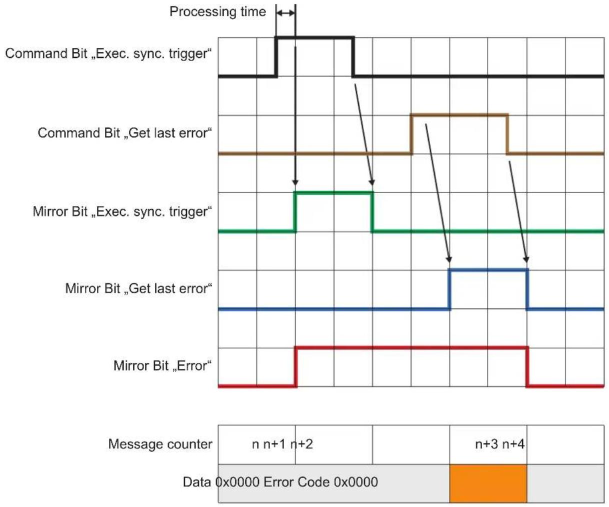
Get last error
This command is used to reset the error bit.
Get connection ID
This command retrieves the connection ID of the current Ethernet/IP connection. The content of the producing assembly mandatory data section is:
- Bytes 0-3: connection ID, 32 bit unsigned integer
Get statistics
This command retrieves the current statistics. The content of the producing assembly mandatory data section is:
- Bytes 0-3: total readings since application start
- Bytes 4-7: passed readings
- Bytes 8-11: failed readings
All values are 32 bit unsigned integers.
Default endianness
The default endianness is in little-endian format.
Activate application
This command activates the application defined by the bytes 6 and 7 of the consuming assembly data section. The bytes 2-5 have to be set to 0. An error is risen if bytes 2-5 are not set to 0.
The data content of the processing assembly is set to 0.
Get application list
This command retrieves the current configuration list. The content of the producing assembly mandatory data section is:
- Bytes 0-3: total number of saved applications, 32 bit unsigned integer
- Bytes 4-7: number of active application, 32 bit unsigned integer
- Bytes 8-n: always a 32 bit unsigned integer for an application number in use
Get IO state
Retrieves the logic state of the given IO identifier. Bytes 4 and 5 of the consuming assembly data section defines the IO ID as a 16 bit unsigned integer value:
- 1->101
- 2->102
- 3->IO3
The bytes 2-3 and 6-7 have to be set to 0. An error is risen if bytes 2-3 or 6-7 are not set to 0.
The data content of the processing assembly is:
- Bytes 0-3: logic state of the IO, 1 for high, 0 for low, 32 bit unsigned integer
Set IO state
This command sets the given state of the given IO. Bytes 4 and 5 of the consuming assembly data section defines the IO ID as a 16 bit unsigned integer value:
- 1->101
- 2->102
- 3->IO3
The bytes 6 and 7 define the logic state of the IO as 16 bit unsigned integer value.
The bytes 2-3 have to be set to 0. An error is risen if bytes 2-3 are not set to 0.
The data content of the processing assembly is set to 0.
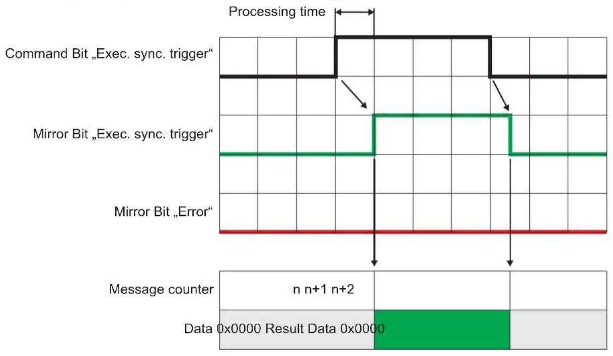
Execute synchronous trigger
This command executes a synchronous trigger. The content of the producing assembly data section depends on the user defined PCIC output for Ethernet/IP.
Activate asynchronous PCIC output
This command activates or deactivates the asynchronous PCIC output for this connection. The bytes 6 and 7 of the consuming assembly data section define the on/off state as a 16 bit unsigned integer value:
- 0 = off
- 1 = on
The bytes 2-5 have to be set to 0. An error is risen if bytes 2-5 are not set to 0.
The data content of the processing assembly is set to 0.
For the Ethernet/IP interface the user shall only be able to select the binary representation of result data.
13.4.3 Extended commands
Use of extended command
The following command executes an extended command. The ID of the extended command is stored as 16 bit integer in bytes 2-3. The remaining data depends on the extended command.
| ID Description | |
| 1 Set temporary application parameterThe ID of the parameter to be changed is stored as unsigned 16 bit integer in bytes 4-5.The value of the parameter is stored as signed 16 bit integer in bytes 6-7. | |
Use of extended command with the depalletising application
| Byte 1 (Bit 7) | 2-3 4-5 6-7 | |||
| Description | Use extended command high / low | Extended command ID1 = set temporaryapplication parameter | Parameter ID1 = DepalSlipSheetDetection2 = Type of the object to detect3 = DepalWidth4 = DepalHeight5 = DepalLength | Parameter value1 = on / 0 = off1 = bag / 0 = boxvalue [mm]value [mm]value [mm] |
13.4.4 Signal sequence with synchronous trigger
FR
13.4.5 Signal sequence with failed trigger
13.5 PROFINET IO
13.5.1 Data structures for output and input frame
Size of output frame
Every output frame sent by the controller contains 8 bytes of data, which consists of command word and command data.
Size of input frame
Every Input frame contains 16 - 450 bytes of data, which are generated by the device in response to the commands received in the output frames. The size of non mandatory data is adjustable by changing the size of the input data in the GSDML file.
| Byte 0-1 2-3 4-5 6-7 8-15 16-49 | ||||||
| Description | Command word for mirroring | Synchronous / asynchronous message identifier | Message counter | Reserved | Mandatory data | Non mandatory data |
Layout of command word
| Bit 0 1-15 | ||
| Description Error bitThis bit has no meaning in the consuming assembly. It is used for signaling an occured error to the PLC | Command bitsEach bit represents a specific command |
Command word
| Description | Error bit | N.a. | N.a. | N.a. | N.a. | N.a. | N.a. | Get last error | Get connection ID | Get statistics | Get statistics | Activate application | Get application list | Get application list | Set IO state | Set IO state | Execute synchronous trigger | Activate asynchronous PCIC output | Use extended command |
Synchronous/asynchronous identifier
| Bit 0 1-15 | ||
| Description Asynchronous message bit | Bits for asynchronous message identifier | |
13.5.2 Functionality of PROFINET IO application
This section describes how to handle the commands sent by the controller. The PLC sends the commands to the device in the output frames by setting the appropriate bit in the command word. The current value of the command word and command data is obtained from the output module by the application.
After detecting that one of the command bits changed the state from 0 to 1, the PROFINET application executes the corresponding command and sets the response in the input frames.
Number of supported PROFINET connections
The O3D3xx running a PROFINET application supports one connection with a single controller.
Initialisation of input and output buffers
After the connection is established, the input and output buffers are initialised with 0 s.
Command execution triggering
As soon as the command bit in the output frame changes from 0 to 1, the corresponding command will be executed.
Handling of multiple command bits
If more than one command bit is set to 1, an error will be reported.
Command execution completion
The PLC has to reset the command bit from 1 to 0 before a new command can be executed. The device has to reset the command word and increase the message counter within the input frame. Mandatory and non mandatory data in the response frame is set to 0 × 0 .
Blocking of asynchronous messages
As long as the command handshake procedure has not been finished, no asynchronous message will be sent by the device.
Client disconnect
If the client is disconnecting before finishing the handshake procedure, the handshake procedure is canceled and all buffers are reset.
General reply to an implemented command
If the command is implemented, the data in the data section is applicable and the execution of the command does not lead to an error. The input frame contains the following data:
- Error bit = 0
Command bits = mirror of the command within the output frame - Asynchronous message bit = 0
- Asynchronous message identifier = 0
- Message counter increased by 1
- Message data set to 0
Reply to an implemented command - reply contains specific data
If the command is implemented, the data in the data section is applicable and the execution of the command does not lead to an error. The input frame contains the following data:
- Error bit = 0
Command bits = mirror of the command within the output frame - Asynchronous message bit = 0
- Asynchronous message identifier = 0
- Message counter increased by 1
- Message data set according to the command definition
Reply to an implemented command with error in data section
If the content of the data section is not suitable to the command, the message is handled as an error. The input frame contains the following data:
- Error bit = 1
Command bits = mirror of the command within the output frame - Asynchronous message bit = 0
- Asynchronous message identifier = 0
- Message counter increased by 1
No error code is sent in the data section. The error code is polled with the "get last error" command. Mandatory and non mandatory data in the response frame will be set to 0x0.
Reply to an implemented command that leads to an error
If the execution of the command leads to an error, the input frame contains the following data:
- Error bit = 1
Command bits = mirror of the command within the output frame - Asynchronous message bit = 0
- Asynchronous message identifier = 0
- Message counter increased by 1
No error code is sent in the data section. The error code is polled with the "get last error" command. Mandatory and non mandatory data in the response frame will be set to 0x0.
Reply to a not implemented command
If a command bit with no functionality is received, it undergoes a transition from 0 -> 1 and the message is handled as an error. The input frame contains the following data:
- Error bit = 1
Command bits = mirror of the command within the output frame - Asynchronous message bit = 0
- Asynchronous message identifier = 0
- Message counter increased by 1
No error code is sent in the data section. The error code is polled with the "get last error" command. Mandatory and non mandatory data in the response frame will be set to 0x0.
Reset of error bit
The error bit will be reset to 0, if
- the error code caused by an command is sent to the controller
- a system error is not present anymore
Queuing of error codes
The Profinet application is able to buffer one system error (the last one) and one command error (also the last one). The buffered system error and PCIC command error will be cleared, after they are read by the PLC with the "get last error" command.
Functionality of asynchronous message bit
If the message contain asynchronous data (frame results, system errors, etc.), the asynchronous message bit must be set to 1.
Bits for asynchronous message identifier
If the message contains asynchronous data, the identifier represents the asynchronous message type:
-
The ticket number for asynchronous results is 0
-
The ticket number for asynchronous error codes is 1
-
The reserved ticket numbers for asynchronous messages are in the range 0-99
Message counter
For each command response sent in the input frame the message counter is increased. The counter starts with value 1. If the maximum counter is reached, it starts with 1 again.
Get last error
This command retrieves the current command and system error. The content of the mandatory data section sent in the input frame is:
- Bytes 0-3 : command error code, 32 bit unsigned integer
- Bytes 4-7: system error code, 32 bit unsigned integer
Get connection ID
This command retrieves the connection ID of the current Profinet connection. The response sent in the input frame contains 16 Bytes of the AR UUID.
Get statistics
This command retrieves the current statistics. The content of the mandatory data section sent in the input frame is:
- Bytes 0-3: total readings since application start
- Bytes 4-7: passed readings
- Bytes 8-11: failed readings
All values are 32 bit unsigned integers.
Default endianness
The default endianness is in little-endian format.
Activate application
This command activates the application defined by the bytes 6 and 7 of the output frame data section. The bytes 2-5 have to be set to 0. An error is risen if bytes 2-5 are not set to 0.
The data content of the input frame is set to 0, after receiving the "Activate application" command.
Get application list
This command retrieves the current configuration list. The content of the response sent in the input frame mandatory data section is:
- Byte 0-3: total number of saved applications, 32 bit unsigned integer
- Bytes 4-7: number of active application, 32 bit unsigned integer
- Bytes 8-n: always a 32 bit unsigned integer for an application number in use
Get IO state
Retrieves the logic state of the given IO identifier. Bytes 4 and 5 of the output frame data section defines the IO ID as a 16 bit unsigned integer value:
- 1->IO1
- 2->102
- 3->IO3
The bytes 2-3 and 6-7 have to be set to 0. An error is risen if bytes 2-3 or 6-7 are not set to 0.
The data sent in the input frame is:
- Byte 0-3: logic state of the requested IO, 1 for high, 0 for low, 32 bit unsigned integer
Set IO state
This command sets the given state of the given IO. Bytes 4 and 5 of the output frame data section defines the IO ID as a 16 bit unsigned integer value:
- 1->IO1
- 2->102
- 3->IO3
The bytes 6 and 7 define the logic state of the IO as 16 bit unsigned integer value.
The bytes 2-3 have to be set to 0. An error is risen if bytes 2-3 are not set to 0.
The data content of the input frame is set to 0, after receiving the "Set IO state" command.
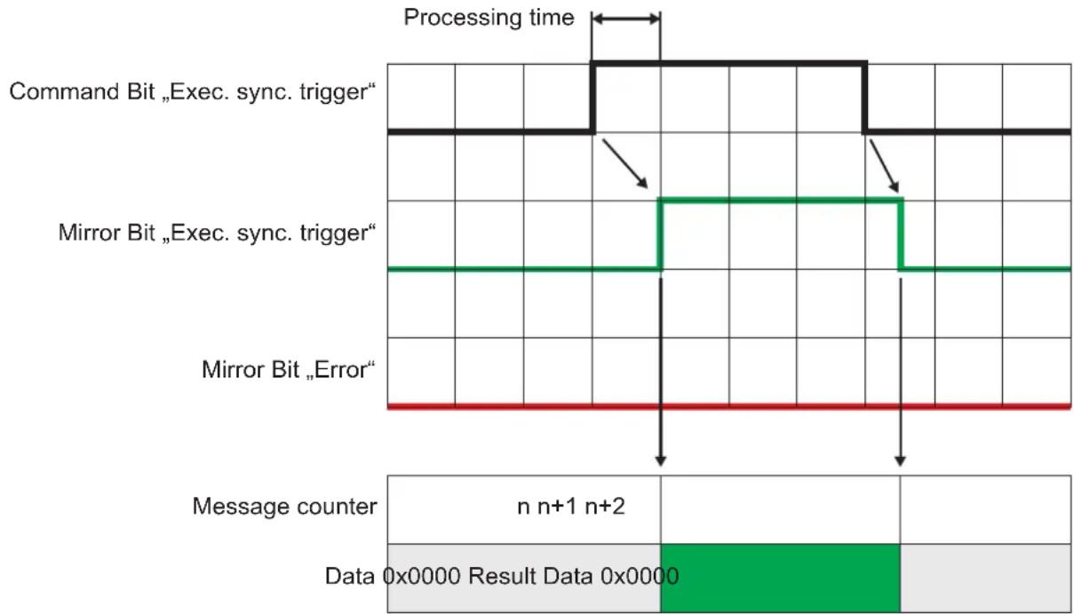
Execute synchronous trigger
This command executes a synchronous trigger. The content of the input frame data section depends on the user defined PCIC output for PROFINET.
Activate asynchronous PCIC output
This command activates or deactivates the asynchronous PCIC output for this connection. The bytes 6 and 7 of the output frame data section define the on/off state as a 16 bit unsigned integer value:
- 0 = off
- 1 = on
The bytes 2-5 have to be set to 0. An error is risen if bytes 2-5 are not set to 0.
The data content of the input frame is set to 0, after receiving the "Activate asynchronous PCIC output" command.
13.5.3 Extended commands
Use of extended command
The following command executes an extended command. The ID of the extended command is stored as 16 bit integer in bytes 2-3. The remaining data depends on the extended command.
| ID Description | |
| 1 Set temporary application parameter The ID of the parameter to be changed is stored as unsigned 16 bit integer in bytes 4-5. The value of the parameter is stored as signed 16 bit integer in bytes 6-7. | |
Use of extended command with the depalletising application
| Byte 0 (Bit 7) 2 | 3 4-5 6-7 | |||
| Description | Use extended command high / low | Extended command ID1 = set temporaryapplication parameter | Parameter ID1 = DepalSlipSheetDetection2 = Type of the object to detect3 = DepalWidth4 = DepalHeight5 = DepaLLength | Parameter value1 = on / 0 = off1 = bag / 0 = boxvalue [mm]value [mm]value [mm] |
13.5.4 Signal sequence with synchronous trigger
13.5.5 Signal sequence with failed trigger
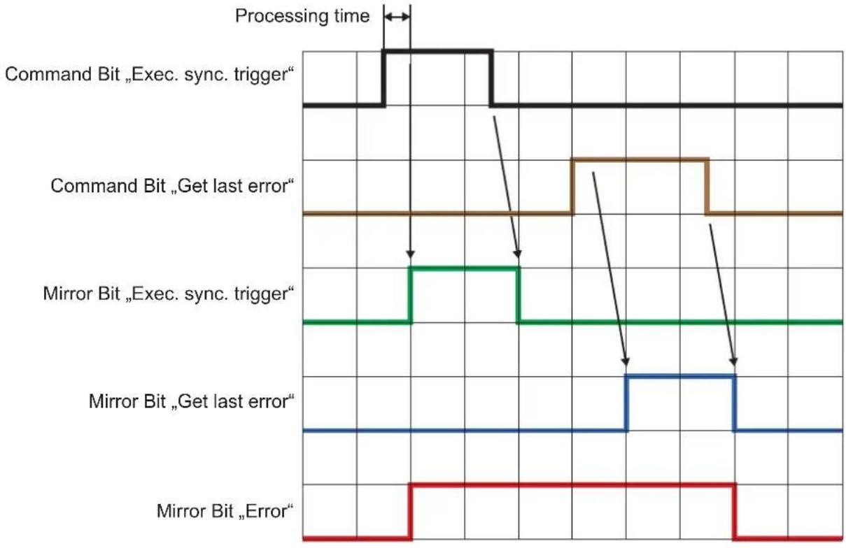
| Message counter | n n+1 | n+2 | n+3 | n+4 | ||
| Data | 0x0000 | Error Code 0x0000 | ||||
- Copyright
- Sending Commands
- Receiving Images
- Image data
- Additional Information for CONFIDENCE_IMAGE
- Configuration of PCIC Output
- Process Interface Command Reference
- a Command (activate application)
- A? Command (occupancy of application list)
- O? Command (request state of a ID)
- p Command (turn PCIC output on or off)
- T? Command (execute synchronous trigger)
- v Command (set current protocol version)
- V? Command (request current protocol version)
- Error codes
- EtherNet/IP
- Data structures for consuming and producing assemblies
- Data to send exceeds processing assembly data section size
- Functionality of the Ethernet/IP application
- State change 0 > 1 of a command bit in consuming assembly
- Multiple state changes
- Reset of command bit state by PLC
- Blocking of asynchronous messages
- Client disconnect
- General reply to an implemented command
- Reply to an implemented command - reply contains specific data
- Reply to an implemented command with error in data section
- Reply to an implemented command that leads to an error
- Reply to a not implemented command
- Reset of error bit
- Functionality of asynchronous message bit
- Bits for asynchronous message identifier
- Message counter
- Get last error
- Get connection ID
- Get statistics
- Default endianness
- Activate application
- Get application list
- Get IO state
- Set IO state
- Execute synchronous trigger
- Activate asynchronous PCIC output
- Extended commands
- Use of extended command
- Use of extended command with the depalletising application
- Signal sequence with synchronous trigger
- Signal sequence with failed trigger
- PROFINET IO
- Data structures for output and input frame
- Size of output frame
- Size of input frame
- Functionality of PROFINET IO application
- Number of supported PROFINET connections
- Initialisation of input and output buffers
- Command execution triggering
- Handling of multiple command bits
- Command execution completion
- Queuing of error codes
- Extended commands
- Signal sequence with synchronous trigger
- Signal sequence with failed trigger
Brand : IFM
Model : O3D355
Category : Video camera