JGCP548WP - Cooker JENN-AIR - Free user manual and instructions
Find the device manual for free JGCP548WP JENN-AIR in PDF.

User questions about JGCP548WP JENN-AIR
0 question about this device. Answer the ones you know or ask your own.
Ask a new question about this device
Download the instructions for your Cooker in PDF format for free! Find your manual JGCP548WP - JENN-AIR and take your electronic device back in hand. On this page are published all the documents necessary for the use of your device. JGCP548WP by JENN-AIR.
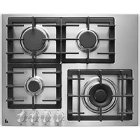
USER MANUAL JGCP548WP JENN-AIR
30" (76.2 cm), 36" (91.4 cm) AND 48" (121.9 cm)
For residential use only
INSTRUCTIONS D'INSTALLATION
TABLES DE CUISSON À GAZ DE TYPE COMMERCIAL
30" (76,2 cm), 36" (91,4 cm) ET 48" (121,9 cm)
Tools and Parts....3
Location Requirements....4
Electrical Requirements 7
Gas Supply Requirements....7
INSTALLATION INSTRUCTIONS......8
Install Cooktop....8
Install Optional Backguard....8
Make Gas Connection....9
Install Griddle 10
Complete Installation ....10
GAS CONVERSIONS....12
Propane Gas Conversion....12
Natural Gas Conversion....14
STRIP CIRCUITS....15
WIRING DIAGRAMS....16
SÉCURITÉ DE LA TABLE DE CUISSON....18
EXIGENCES D'INSTALLATION ....19
Installer: Leave installation instructions with the homeowner.
Homeowner: Keep installation instructions for future reference.
IMPORTANT :
Your safety and the safety of others are very important.
We have provided many important safety messages in this manual and on your appliance. Always read and obey all safety messages.

This is the safety alert symbol.
This symbol alerts you to potential hazards that can kill or hurt you and others.
All safety messages will follow the safety alert symbol and either the word "DANGER" or "WARNING."
These words mean:
! DANGER
You can be killed or seriously injured if you don't immediately follow instructions.
WARNING
You can be killed or seriously injured if you don't follow instructions.
All safety messages will tell you what the potential hazard is, tell you how to reduce the chance of injury, and tell you what can happen if the instructions are not followed.
WARNING: If the information in these instructions is not followed exactly, a fire or explosion may result causing property damage, personal injury or death.
- Do not store or use gasoline or other flammable vapors and liquids in the vicinity of this or any other appliance.
-
WHAT TO DO IF YOU SMELL GAS:
-
Do not try to light any appliance.
- Do not touch any electrical switch.
- Do not use any phone in your building.
- Immediately call your gas supplier from a neighbor's phone. Follow the gas supplier's instructions.
- If you cannot reach your gas supplier, call the fire department.
- Installation and service must be performed by a qualified installer, service agency or the gas supplier.
WARNING: Gas leaks cannot always be detected by smell.
Gas suppliers recommend that you use a gas detector approved by UL or CSA.
For more information, contact your gas supplier.
If a gas leak is detected, follow the "What to do if you smell gas" instructions.
IMPORTANT: Do not install a ventilation system that blows air downward toward this gas cooking appliance. This type of ventilation system may cause ignition and combustion problems with this gas cooking appliance resulting in personal injury or unintended operation.
In the State of Massachusetts, the following installation instructions apply:
■ Installations and repairs must be performed by a qualified or licensed contractor, plumber, or gas fitter qualified or licensed by the State of Massachusetts.
■ Acceptable Shut-off Devices: Gas Cocks and Ball Valves installed for use shall be listed.
■ A flexible gas connector, when used, must not exceed 4 feet (121.9 cm).
INSTALLATION REQUIREMENTS
Tools and Parts
Gather the required tools and parts before starting installation. Read and follow the instructions provided with any tools listed here.
Tools Needed
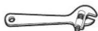
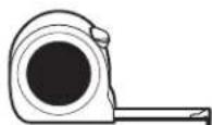
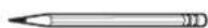
Adjustable wrench Tape measure Marker or pencil
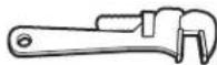
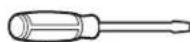
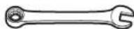
Pipe wrench Flat-blade screwdriver 15/16" (24 mm) combination wrench
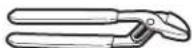
Wrench or channel lock pliers Pipe-joint compound resistant to Propane gas
Noncorrosive leak-detection solution
For Propane/Natural Gas Conversions
Adjustable wrench Drive ratchet 1/2" (13 mm) deep-well socket
7 mm nut driver Masking tape
Parts Supplied
Check that all parts are included.
■Gas pressure regulator
■Burner grates
■Burner bases and burner caps
■Griddle drip tray (on griddle models)
■Foam tape
■Propane orifice package (W10393255)
■Conversion label (W10393342)
NOTE: The cooktop is manufactured for use with Natural gas. To convert to Propane gas, see the "Gas Conversions" section.
Optional Backguards
48" (121.9 cm) models and grill models must be installed with a backsplash if installing at zero clearance to a combustible backwall. See the "Cabinet Dimensions" section in the "Location Requirements" section for installation requirements.
■36" (91.4 cm) Retractable Backguard Order Part Number 8284756
■48" (121.9 cm) Retractable Backguard Order Part Number 8284755
■9" (22.9 cm) Backguard for 36" (91.4 cm) Cooktops Order Part Number W10115776
■9" (22.9 cm) Backguard for 48" (121.9 cm) Cooktops Order Part Number W10115777
■33 1/2" (85.0 cm) Retractable Backguard with Wire Shelf for 36" (91.4 cm) Cooktops
Order Part Number W10285448
■33 ^1/_2 " (85.0 cm) Retractable Backguard with Wire Shelf for 48" (121.9 cm) Cooktops
Order Part Number W10285449
To order, see the “Assistance or Service” section of the Use and Care Guide.
Check local codes and consult gas supplier. Check existing gas supply and electrical supply. See the “Electrical Requirements” and “Gas Supply Requirements” sections.
High Altitude Conversion
To convert the cooktop for elevations above 6,560 ft (1,999.5 m), order a High Altitude Conversion Kit.
■Part Number W10394296: Propane gas high altitude
■Part Number W10394295: Natural gas high altitude
To order, see the "Assistance or Service" section of the Use and Care Guide.
Location Requirements
IMPORTANT: Observe all governing codes and ordinances. Do not obstruct flow of combustion and ventilation air.
It is the installer's responsibility to comply with installation clearances specified on the model/serial/rating plate. The model/serial/rating plate is located on the underside of the cooktop burner base.
■It is recommended that a 600 CFM (17.0 m ^3 /hr) or larger vent hood be installed above the cooktop.
■It is not recommended that a microwave hood combination be mounted above the cooktop.
■The cooktop should be installed in a location away from strong draft areas, such as windows, doors, and strong heating vents or fans.
■All openings in the wall or floor where cooktop is to be installed must be sealed.
■Cabinet opening dimensions that are shown must be used. Given dimensions are minimum clearances.
■Grounded electrical supply is required. See the “Electrical Requirements” section.
■Proper gas supply connection must be available. See the "Gas Supply Requirements" section.
■The cooktop is designed to hang from the countertop by its side or rear flanges.
■The gas and electric supply should be located as shown in the "Gas and Electric Connection Locations" section so that they are accessible without requiring removal of the cooktop.
■Provide cutout in left rear corner of cutout enclosure as shown to provide clearance for gas inlet, power supply cord, and to allow the rating label to be visible.
IMPORTANT: To avoid damage to your cabinets, check with your builder or cabinet supplier to make sure that the materials used will not discolor, delaminate, or sustain other damage.
Mobile Home - Additional Installation Requirements
The installation of this cooktop must conform to the Manufactured Home Construction and Safety Standard, Title 24 CFR, Part 3280 (formerly the Federal Standard for Mobile Home Construction and Safety, Title 24, HUD Part 280). When such standard is not applicable, use the Standard for Manufactured Home Installations, ANSI A225.1/NFPA 501A or local codes.
In Canada, the installation of this cooktop must conform with the current standards CAN/CSA-A240-latest edition or with local codes.
Product Dimensions
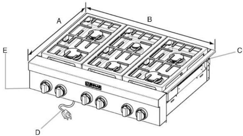
A. 27 ^1/8 (68.9 cm)
B. 30" (76.2 cm) cooktop: 29 ^7/8 " (75.9 cm)
36" (91.4 cm) cooktop: 35 ^3/4 " (90.8 cm)
48" (121.9 cm) cooktop: 47 ^7/8 " (121.6 cm)
C. Island trim or optional backguard
D. 36" (91.4 cm) long 3 prong grounding-type power supply cord
E. Model/serial/rating plate (located on the underside of the cooktop burner base)
Side View of Cooktop
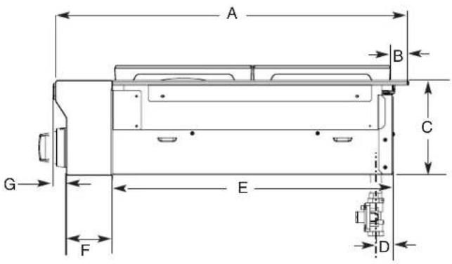
A. 27^3/_4 " (70.5 cm)
B. 1 ^1/4 " (3.2 cm)
C. 7 ^7 /16" (18.8 cm)
D. Gas inlet is located 1^7/s^16 (4.8 cm) from the back of the cooktop burner base and 4^7/s^16 (12.4 cm) in from left-hand side of the cooktop burner base.
E. 22" (55.9 cm)
F. _18'' (8.4 cm)
G. 9/16" (14 mm)
Gas and Electric Connection Locations
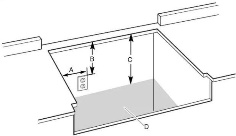
A. Grounded 3 prong outlet should be located on left-hand side of the cutout 16" (40.6 cm) max. from enclosure sidewall
B. 10" (25.4 cm) min. clearance from countertop to top of the outlet
C. 14" (35.6 cm) countertop to the gas supply line
D. Gas supply line should be located in this area on rear or side walls or the supply line can come up through the floor.
NOTE: Solid side and bottom of cutout enclosure not shown.
Cabinet Requirements
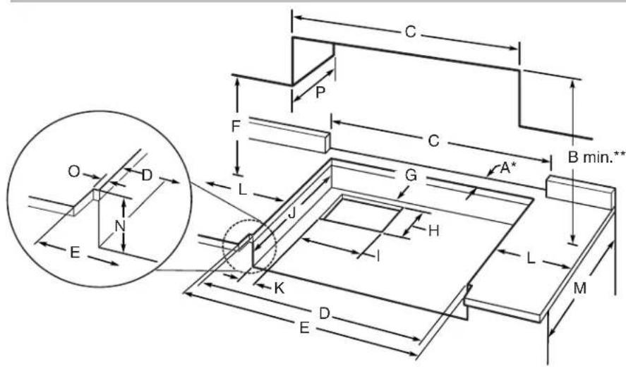
| Size Model A* | B**Cooktop Cutout to Back Wall | C Cooktop to Cabinet | D Optional Backguard and Upper Cabinet Opening | E Cabinet and Countertop | E Countertop Only | |
| 30" (76.2 cm) | JGCP430 1 | ^3/_4 " (4.4 cm)* | 30" (76.2 cm) 30" (76.2 cm) | 29^1/_4 " (74.3 cm) | 30" (76.2 cm) or 29^7/_8 " (75.9 cm) for zero clearance | |
| 36" (91.4 cm) | JGCP436 JGCP536 | ^13/_4 " (4.4 cm)* 42" (106.7 cm) 36" (91.4 cm) 35 | ^1/_4 " (89.5 cm) 36" (91.4 cm) or 35^1/_4 " (90.8 cm) for zero clearance | |||
| 48" (121.9 cm) | JGCP548 1 | ^3/_4 " (4.4 cm)* 42" (106.7 cm) 48" (121.9 cm) 47 | ^1/_4 " (120.0 cm) 48" (121.9 cm) or 47^7/_8 " (121.6 cm) for zero clearance | |||
* NOTE: If backwall is constructed of a combustible material and a backguard is not installed, a minimum clearance of dimension A + 3" (7.6 cm) is required for 36" (91.4 cm) and 48" (121.9 cm) cooktops.
**NOTES: Dimension "B" can be reduced by 6" (15.2 cm) when bottom of wood or metal cabinet is covered by not less than 0.25" (6.4 mm) flame retardant millboard covered with not less than No. 28 MSG sheet metal, 0.015" (0.4 mm) stainless steel, 0.024" (0.6 mm) aluminum, or 0.020" (0.5 mm) copper.
If installing a range hood above the cooktop, follow the range hood instructions for dimensional clearances above the cooktop surface.
Electrical Requirements
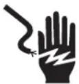
WARNING

Electrical Shock Hazard
Plug into a grounded 3 prong outlet.
Do not remove ground prong.
Do not use an adapter.
Do not use an extension cord.
Failure to follow these instructions can result in death, fire, or electrical shock.
IMPORTANT: The cooktop must be electrically grounded in accordance with local codes and ordinances or, in the absence of local codes, with the National Electrical Code, ANSI/NFPA 70 or Canadian Electrical Code, CSA C22.1.
This cooktop is equipped with an electronic ignition system that will not operate if plugged into an outlet that is not properly polarized.
If codes permit and a separate ground wire is used, it is recommended that a qualified electrical installer determine that the ground path is adequate.
A copy of the above code standards can be obtained from:
National Fire Protection Association
1 Batterymarch Park
Quincy, MA 02169-7471
CSA International
8501 East Pleasant Valley Road
Cleveland, Ohio 44131-5575
■A 120-volt, 60-Hz, AC-only, 15-amp, fused electrical circuit is required. A time-delay fuse or circuit breaker is also recommended. It is recommended that a separate circuit serving only this cooktop be provided.
Electronic ignition systems operate within wide voltage limits, but proper grounding and polarity are necessary. Check that the outlet provides 120-volt power and is correctly grounded.
■The wiring diagrams are provided with this cooktop. The wiring diagrams are located inside the control console and in the "Wiring Diagrams" section.
Gas Supply Requirements
WARNING
Explosion Hazard
Use a new CSA International approved gas supply line.
Install a shut-off valve.
Securely tighten all gas connections.
If connected to propane, have a qualified person make sure gas pressure does not exceed 14" (36 cm) water column.
Examples of a qualified person include:
licensed heating personnel, authorized gas company personnel, and authorized service personnel.
Failure to do so can result in death, explosion, or fire.
Observe all governing codes and ordinances.
IMPORTANT: This installation must conform with all local codes and ordinances. In the absence of local codes, installation must conform with American National Standard, National Fuel Gas Code ANSI Z223.1 - latest edition or CAN/CGA B149 - latest edition.
IMPORTANT: Leak testing of the cooktop must be conducted according to the manufacturer's instructions.
Type of Gas
Natural Gas:
This cooktop is factory-set for use with Natural gas. To convert to Propane gas, see the Gas Conversion instructions provided in the package containing literature. The model/serial/rating plate located on the left underside of the cooktop burner base has information on the types of gas that can be used. If the types of gas listed do not include the type of gas available, check with the local gas supplier.
Propane Gas conversion:
Conversion must be done by a qualified service technician.
No attempt shall be made to convert the cooktop from the gas specified on the model/serial/rating plate for use with a different gas without consulting the serving gas supplier. To convert to Propane gas, use the Propane gas conversion kit provided with the cooktop and see the “Gas Conversions” section.
Gas Supply Line
■ Provide a gas supply line of 3/4" (19 mm) rigid pipe to the cooktop location. A smaller size pipe on longer runs may result in insufficient gas supply. With Propane gas, piping or tubing size can be 1/2" (13 mm) minimum. Usually, Propane gas suppliers determine the size and materials used in the system.
NOTE: Pipe-joint compounds that resist the action of Propane gas must be used. Do not use TEFLON ^®† tape.
■Flexible metal appliance connector:
■If local codes permit, a new CSA design-certified, 4-5 ft (122-152 cm) long, 5/8" (16 mm) or 3/4" (19 mm) I.D., flexible metal appliance connector may be used for connecting the cooktop to the gas supply line.

■A 1/2" (13 mm) male pipe thread is needed for connection to the female pipe threads of the inlet to the appliance pressure regulator.
■Do not kink or damage the flexible metal tubing when moving the cooktop.
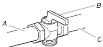
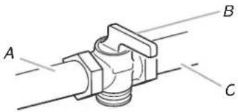
■Must include a shut-off valve:
Install a manual gas line shut-off valve in an easily accessible location. Do not block access to shut-off valve. The valve is for turning on or shutting off gas to the cooktop.
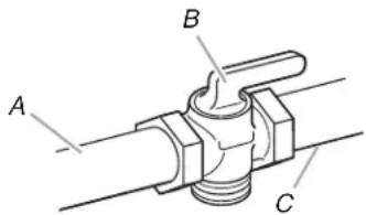
A. Gas supply line
B. Shut-off valve "open" position
C. To cooktop
Gas Pressure Regulator
The gas pressure regulator supplied with this cooktop must be used. The inlet pressure to the regulator should be as follows for proper operation:
Natural Gas:
Minimum pressure: 15.2 cm WCP
Maximum pressure: 35.6 cm WCP
Propane Gas:
Minimum pressure: 27.9 cm WCP
Maximum pressure: 35.6 cm WCP
Contact local gas supplier if you are not sure about the inlet pressure.
Burner Input Rating — Altitude
Input ratings shown on the model/serial/rating plate are for elevations up to 2,000 ft (609.6 m).
For elevations above 2,000 ft (609.6 m), ratings need to be reduced at a rate of 4% for each 1,000 ft (304.8 m) above sea level (not applicable for Canada).
Gas Supply Pressure Testing
Gas supply pressure for testing regulator must be at least 2.5 cm water column pressure above the manifold pressure shown on the model/serial/rating plate.
Line pressure testing above 1/2 psi (3.5 kPa) gauge (35.6 cm WCP)
The cooktop and its individual shut-off valve must be disconnected from the gas supply piping system during any pressure testing of that system at test pressures in excess of 1/2 psi (3.5 kPa).
Line pressure testing at 1/2 psi (3.5 kPa) gauge (35.6 cm WCP) or lower
The cooktop must be isolated from the gas supply piping system by closing its individual manual shut-off valve during any pressure testing of the gas supply piping system at test pressures equal to or less than 1/2 psi (3.5 kPa).
INSTALLATION INSTRUCTIONS
Install Cooktop
WARNING
Excessive Weight Hazard
Use two or more people to move and install cooktop.
Failure to do so can result in back or other injury.
Write down the model and serial numbers before installing the cooktop. Both numbers are located on the left front underside of the burner base.
Unpack the parts supplied with your cooktop. The parts shipped with the cooktop depend on your model ordered. See the "Tools and Parts" section for a complete list of parts supplied with your cooktop.
The pressure regulator and flexible stainless steel gas supply line connector can be assembled to the cooktop now or after the cooktop is installed in the cutout. See the “Make Gas Connection” section.
- Decide on the final location for the cooktop.
- Using two or more people, place the cooktop upside down on a covered surface.
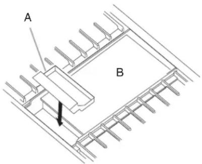
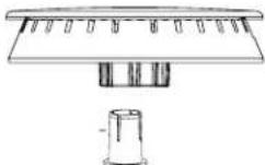
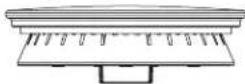
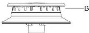
- Remove foam strip from packing containing literature. Remove backing from foam strip. Apply foam strip adhesive-side down along the left and right sides of the cooktop trim.
NOTE: The foam strip helps the cooktop sit flat on uneven counters and avoids damage to the countertop surface.
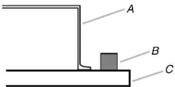
A. Cooktop base
B. Foam strip
C. Cooktop
- Using two or more people, turn cooktop right side up.
Install Optional Backguard
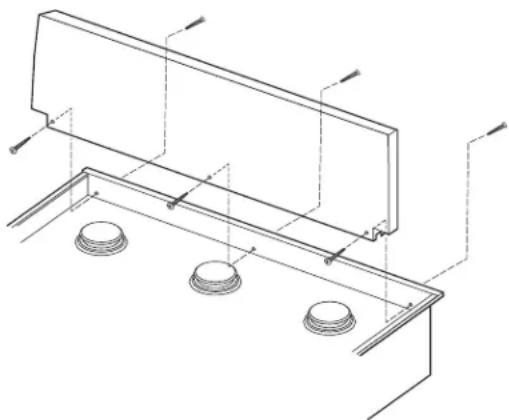
36" (91.4 cm) and 48" (121.9 cm) models may require a backguard. See the "Cabinet Dimensions" section in the "Location Requirements" section for installation requirements. See the "Tools and Parts" section for information on ordering.
Remove island trim and attach backguard using six screws; insert three from the front and three from the back (9" [22.9 cm] backguard shown).
natural_image
Technical line drawing of a structural support frame with mounting holes and beams (no text or symbols)Make Gas Connection
WARNING
Explosion Hazard
Use a new CSA International approved gas supply line.
Install a shut-off valve.
Securely tighten all gas connections.
If connected to propane, have a qualified person make sure gas pressure does not exceed 14" (36 cm) water column.
Examples of a qualified person include:
licensed heating personnel, authorized gas company personnel, and authorized service personnel.
Failure to do so can result in death, explosion, or fire.
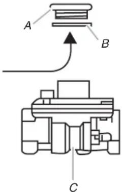
To Assemble Pressure Regulator:
- Using two or more people, stand the cooktop on its side or back.
- Connect the flexible stainless steel connector to the pressure regulator using a 1/2" (13 mm) male pipe thread adapter.
A combination of pipe fittings must be used to connect the cooktop to the existing gas line. The following shows a typical connection. Your connection may be different, according to the supply line type, size, and location.
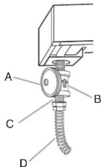
A. Gas pressure regulator
B. Regulator - Must be installed with arrow pointing up to cooktop bottom
C. Adapter - Must have 1/2" (13 mm) male pipe thread
D. CSA approved flexible stainless steel gas supply line
- Install the pressure regulator with the arrow pointing up toward the bottom of the cooktop burner base and in a position where you can reach the regulator cap.
IMPORTANT: All connections must be wrench-tightened.
Do not make connections to the gas regulator too tight. Making the connections too tight may crack the regulator and cause a gas leak. Do not allow the regulator to turn on the pipe when tightening fittings.
Use only pipe-joint compound made for use with Natural and Propane gas. Do not use TEFLON® tape.
You will need to determine the fittings required depending on your installation.
- Place cooktop into the countertop cutout.
NOTE: Check that the front edge of the cooktop is parallel to the front edge of the countertop. If repositioning is needed, lift entire cooktop up from cutout to avoid scratching the countertop.
Typical flexible connection
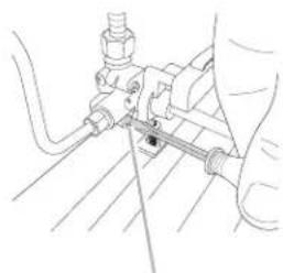
- Apply pipe-joint compound made for use with Propane gas to the smaller thread ends of the flexible connector adapters (see B and F in the following illustration).
- Attach one adapter to the gas pressure regulator and the other adapter to the gas shut-off valve. Tighten both adapters.
- Use a 15/16" (24 mm) combination wrench and channel lock pliers to attach the flexible connector to the adapters. Check that connector is not kinked.
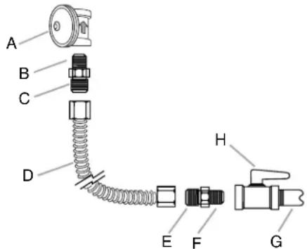
A. Gas pressure regulator
B. Use pipe-joint compound.
C. Adapter - must have 1/2" (13 mm) male pipe thread
D. Flexible connector
E. Adapter
F. Use pipe-joint compound.
G. 1/2" (13 mm) or 3/4" (19 mm) gas pipe
H. Manual gas shut-off valve
Complete Connection
- Open the manual shut-off valve in the gas supply line. The valve is open when the handle is parallel to the gas pipe.
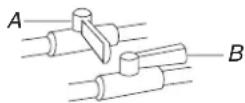
A. Closed valve
B. Open valve
- Test all connections by brushing on an approved noncorrosive leak-detection solution. If bubbles appear, a leak is indicated. Correct any leak found.
- Remove cooktop burner caps, burner bases, and grates from parts package. Place burner bases on cooktop. Place burner caps on burner bases. Place grates over burners and caps.
WARNING
Electrical Shock Hazard
Plug into a grounded 3 prong outlet.
Do not remove ground prong.
Do not use an adapter.
Do not use an extension cord.
Failure to follow these instructions can result in death, fire, or electrical shock.
- Plug into a grounded 3 prong outlet.
- Check the operation of the surface burners. See "Check Operation of Cooktop Burners" section in the "Complete Installation" section.
- If your model has a griddle, see the "Install Griddle" section.
Install Griddle
(on griddle models)
The griddle is factory installed.
- Place drip tray in the well at the front of the griddle. Slide tray toward the back until it stops.
A. Griddle drip tray
B. Griddle
- Clean griddle before using. Refer to the Use and Care Guide.
Complete Installation
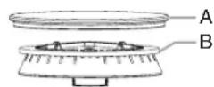
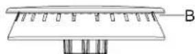
Install Burner Bases and Burner Caps
Install the burner base, making sure the igniter electrode is properly aligned with the base. Place burner caps on top of burner bases. If burner caps are not properly positioned, surface burners will not light.
Ultra Power™ Dual-Flame Burner
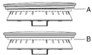
natural_image
Two technical diagrams labeled A and B showing layered or structural components with no visible text or symbols.A. Incorrect
B. Correct
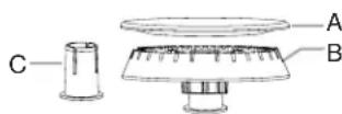
Professional Burner
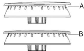
natural_image
Technical line drawing of a mechanical component with labeled parts A and B (no text or symbols beyond labels)A. Incorrect
B. Correct
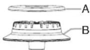
Simmer/Melt Burner
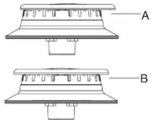
natural_image
Technical line drawing of a mechanical component with two views labeled A and B (no text or symbols present)A. Incorrect
B. Correct
Electronic Ignition System
Initial lighting and gas flame adjustments
Cooktop burners use electronic igniters in place of standing pilots. When the cooktop control knob is turned to any position, the system creates a spark to light the burner. This sparking continues until the flame is lit or the knob is turned to OFF.
Check Operation of Cooktop Burners
Push in and turn each control knob to the LITE position.
The surface burners and grill flames should light within 4 seconds. The first time a burner is lit, it may take longer than 4 seconds to light because of air in the gas line.
After verifying the proper burner operation, turn the control knobs to OFF.
If burners do not light properly:
■Turn cooktop control knob to the OFF position.
■Check that the cooktop is plugged in and the circuit breaker has not tripped or the fuse has not blown.
- Check that the gas shut-off valves are set to the "open" position.
■Check that burner caps are properly positioned on burner bases.
Repeat start-up. If a burner does not light at this point, contact your dealer or authorized service company for assistance.
If you need Assistance or Service:
Please reference the "Assistance or Service" section of the Use and Care Guide or contact the dealer from whom you purchased your cooktop.
Flame Height
The cooktop flame should be a steady blue flame approximately 1/4" (6.4 mm) high.
Dual Flame Burner
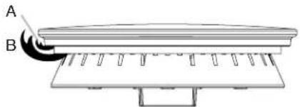
natural_image
Diagram of a mechanical assembly with labeled parts A and B, showing layered structure without any text or symbols.A. Upper (simmer) flame
B. Lower flame
Single Flame Burner
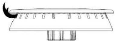
natural_image
Simple line drawing of a curved structure with vertical supports and a crescent moon at the top (no text or symbols)To Adjust Flame Height:
- Unplug cooktop or disconnect power.
- Remove burner grates.
- Remove the control knobs.
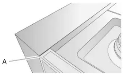
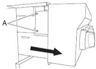
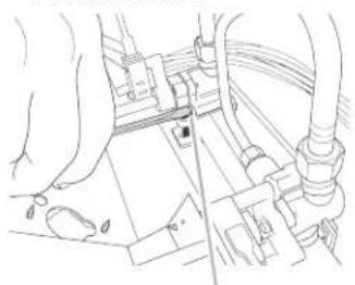
- Pull cooktop forward to expose the control console screws on the side of the cooktop burner base.
- Remove the two screws on each side of the cooktop burner base that hold the control console in place.
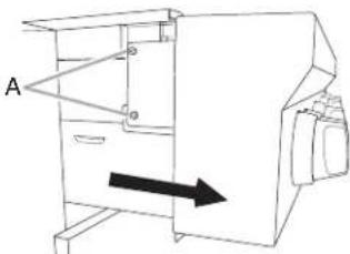
natural_image
Line drawing of a mechanical device with an arrow indicating direction (no text or symbols)A. Console attachment screws
- Disconnect wiring from the control console.
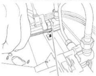
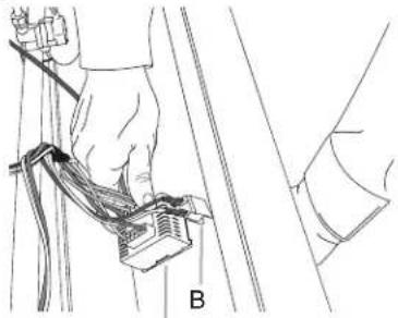
On Griddle Models:
Support the control console in the middle with one arm and disconnect the griddle switch connectors and the grill indicator light with the other hand.
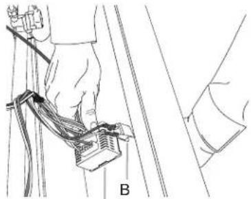
natural_image
Line drawing of a person using a cable or cable device on a pole, with no visible text or symbolsA
A. Griddle switch connectors
B. Grill indicator light connector
- Remove console and set aside.
-
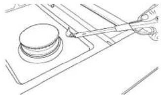
Remove the round gasket from the valve stem.
-
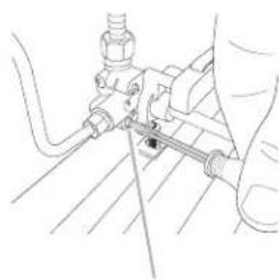
Put a control knob onto the valve stem of the burner you want to adjust.
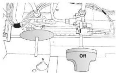
- Turn the control knob to LO and light the burner using a butane extension lighter.
natural_image
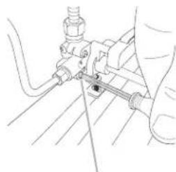
Technical line drawing of a mechanical assembly with a cylindrical component and intersecting rods (no text or symbols)- Remove the control knob.
- Use a flat-blade screwdriver to adjust the flame height. Tighten screw to reduce flame height. Loosen screw to increase flame height.
NOTE: When you are converting to Propane gas, the screw should be tightened down completely on the single output valves. The dual output valve should not be adjusted.
natural_image
Line drawing of hands operating a mechanical device with hoses and components (no text or symbols)A
natural_image
Technical line drawing of a mechanical assembly with hoses and components (no text or symbols)B
A. Single flame burner adjustment screw (on right side of valve)
B. Dual flame burner adjustment screw (on left side of valve)
- When finished adjusting the flame height, put a control knob back onto the valve stem and turn off the burner.
- Remove the control knob.
- Replace the round gasket.
- Repeat steps 8 through 15 for any other burners that need adjustment.
- Reinstall the control console. Support the control console in the middle with one arm and reconnect the griddle switch connectors and/or grill indicator light connector.
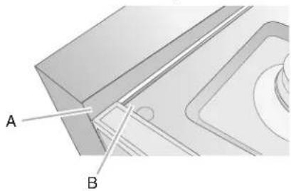
- Set the control console back into place on the cooktop. For a proper fit, the flange of the control console must hook over the lip on the front of the cooktop.
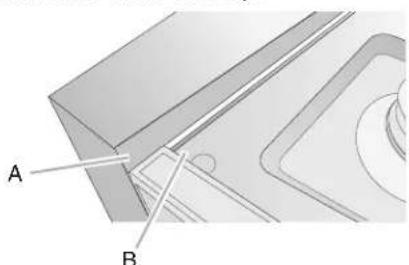
natural_image
Technical diagram of a mechanical component with labeled parts A and B (no text or symbols beyond labels)A. Control console flange
B. Front lip of range cooktop
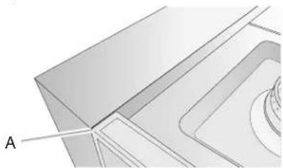
- Check that the control console is flush with the top edge of the cooktop.
natural_image
Pure technical diagram showing a 3D mechanical part with no visible text, numbers, or symbolsA. Flush with top of cooktop
-
Replace the two screws on each side of the control console.
-
Push the cooktop back into place in the cutout.
- Replace the control knobs.
- Replace burner grates.
- Plug in cooktop or reconnect power.
- Test the flame by turning the control from LO to HI, checking the flame at each setting.
GAS CONVERSIONS
IMPORTANT: Gas conversions from Natural gas to Propane gas must be done by a qualified installer.
WARNING
Explosion Hazard
Use a new CSA International approved gas supply line. Install a shut-off valve.
Securely tighten all gas connections.
If connected to propane, have a qualified person make sure gas pressure does not exceed 14" (36 cm) water column.
Examples of a qualified person include: licensed heating personnel, authorized gas company personnel, and authorized service personnel.
Failure to do so can result in death, explosion, or fire.
Propane Gas Conversion
- Turn the manual shut-off valve to the closed position.
A. To cooktop
B. Shut-off valve (closed position)
C. Gas supply line
- Unplug cooktop or disconnect power.
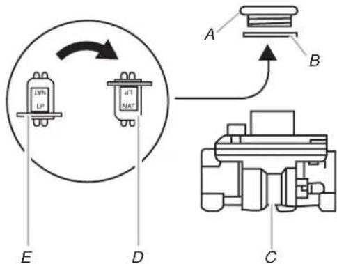
To Convert Gas Pressure Regulator
- Remove the access cap by using a wrench, turning the access cap counterclockwise.
- Remove spring retainer from the cap by pushing against the flat side of the spring retainer. Look at the spring retainer to locate the "NAT" or "LP" position. Turn over the spring retainer so the "LP" is showing on the bottom. Snap the spring retainer back into the cap. Reinstall the cap onto the regulator.
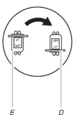
A. Access cap
B. Gasket
C. Gas pressure regulator
D. LP position
E. NAT position
- Test the gas pressure regulator and gas supply line.
The regulator must be checked at a minimum 2.5 cm water column above the set pressure. The inlet pressure to the regulator should be as follows for operation and checking the regulator setting:
Propane Gas:
Minimum pressure: 27.9 cm WCP
Maximum pressure: 35.6 cm WCP
Gas Supply Pressure Testing
Gas supply pressure for testing regulator must be at least 2.5 cm water column pressure above the manifold pressure shown on the model/serial/rating plate.
Line pressure testing above 1/2 psi (3.5 kPa) gauge (35.6 cm WCP)
The cooktop and its individual shut-off valve must be disconnected from the gas supply piping system during any pressure testing of that system at test pressures in excess of 1/2 psi (3.5 kPa).
Line pressure testing at 1/2 psi (3.5 kPa) gauge (35.6 cm WCP) or lower
The cooktop must be isolated from the gas supply piping system by closing its individual manual shut-off valve during any pressure testing of the gas supply piping system at test pressures equal to or less than 1/2 psi (3.5 kPa).
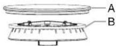
To Convert Surface Burners
- If installed, remove the burner grates.
- Remove burner cap.
- Remove the burner base.
Large Dual Burner
A. Burner cap
B. Burner base
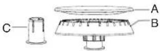
Medium Burner
A. Burner cap
B. Burner base
C. Choke (for use with medium burner, Propane gas only)
Small Burner
A. Burner cap
B. Burner base
-
Apply masking tape to the end of a 7 mm nut driver to help hold the gas orifice spud in the nut driver while changing it. Insert nut driver into gas opening and press down onto the gas orifice spud, and remove by turning the gas orifice spud counterclockwise and lifting out. Set gas orifice spud aside.
-
Replace with correct Propane gas orifice spud. See the "Propane Gas Orifice Spud/Hood Chart."
Burner orifice spud
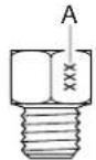
A. Size stamp or color
Use the following chart to find the exact orifice spud placement.
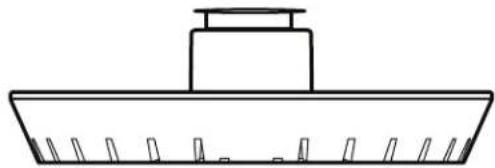
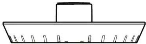
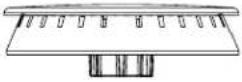
Fully insert choke into bottom of medium burner base. Choke should snap into place. Refer to illustration to verify that choke is fully seated.
NOTE: Chokes are placed on medium burners only.
natural_image
Simple line drawing of a boat hull with no text or symbolsIncorrectly seated choke
natural_image
Simple line drawing of a rectangular object with a central handle and evenly spaced vertical slots (no text or symbols)Correctly seated choke
Propane Gas Orifice Spud/Hood Chart
| Burner Rating | Color Size Burner Style |
3,000 BTUs Blue 0.55 mm Small burners
11,000 BTUs Yellow 0.97 mm Medium burners
Choke
| 14,000 BTUs Red/Green | 1.05 mm | Large burner - main |
| Green | 0.35 mm | Large burner - simmer |
- Place Natural gas orifice spuds in plastic parts bag for future use and keep with package containing literature.
NOTE: There may be extra orifices in your kit.
-
Replace the burner base.
-
Replace burner cap.
-
Repeat steps 2 through 8 for the remaining burners.
- Unplug cooktop or disconnect power.
- Remove the control knobs.
- Pull cooktop forward to expose the control console screws on the side of the cooktop burner base.
- Remove the 2 screws on each side of the cooktop burner base that hold the control console in place.
natural_image
Technical line drawing of a mechanical device with labeled component A and directional arrow (no text or symbols beyond label)A. Console attachment screws
- Disconnect wiring from the control console.
On Griddle Models:
Support the control console in the middle with one arm and disconnect the griddle switch connectors and the grill indicator light with the other hand.
natural_image
Technical line drawing of a hand holding wires and a device, with no visible text or symbolsA
A. Griddle switch connectors
B. Grill indicator light connector
- Remove console and set aside.
- Remove the round gasket from the valve stem.
- Use a flat-blade screwdriver to completely screw down all burner screws.
natural_image
Line drawing of hands operating a mechanical device with hoses and connectors (no text or symbols)A
natural_image
Technical line drawing of a mechanical assembly with no visible text or symbolsB
A. Single flame burner adjustment screw (on right side of valve)
B. Dual flame burner adjustment screw (on left side of valve)
-
Replace the round gasket.
-
Reinstall the control console. Support the control console in the middle with one arm and reconnect the griddle switch connectors and/or grill indicator light connector.
-
Set the control console back into place on the cooktop. For a proper fit, the flange of the control console must hook over the lip on the front of the cooktop.
natural_image
Technical diagram of a mechanical component with labeled parts A and B (no text or symbols beyond labels)A. Control console flange
B. Front lip of range cooktop
- Check that the control console is flush with the top edge of the cooktop.
natural_image
Technical diagram of a mechanical component with labeled section A (no text or symbols present)A. Flush with top of cooktop
- Replace the two screws on each side of the control console.
- Push the cooktop back into place in the cutout.
- Replace the control knobs.
- Replace burner grates.
- Plug in cooktop or reconnect power.
- Test the flame by turning the control from LO to HI, checking the flame at each setting.
Complete Installation
- Refer to the "Make Gas Connection" section for properly connecting the cooktop to the gas supply.
- Refer to the "Electronic Ignition System" section for proper burner ignition, operation, and burner flame adjustments.
IMPORTANT: You may have to adjust the LO setting for each cooktop burner.
Checking for proper cooktop burner flame is very important. The small inner cone should have a very distinct blue flame 1/4" (6,4 mm) to 1/2" (13 mm) long. The outer cone is not as distinct as the inner cone. Propane gas flames have a slightly yellow tip.
- Refer to the "Complete Installation" section in the "Installation Instructions" section of these instructions to complete this procedure.
Natural Gas Conversion
- Turn the manual shut-off valve to the closed position.
A. To cooktop
B. Shut-off valve (closed position)
C. Gas supply line
- Unplug cooktop or disconnect power.
To Convert Gas Pressure Regulator
- Remove the access cap by using a wrench, turning the access cap counterclockwise.
- Remove spring retainer from the cap by pushing against the flat side of the spring retainer. Look at the spring retainer to locate the "LP" or "NAT" position. Turn over the spring retainer so the "NAT" is showing on the bottom. Snap the spring retainer back into the cap. Reinstall the cap onto the regulator.
A. Access cap
B. Gasket
C. Gas pressure regulator
D. NAT position
E. LP position
- Test the gas pressure regulator and gas supply line.
The regulator must be checked at a minimum 2.5 cm water column above the set pressure. The inlet pressure to the regulator should be as follows for operation and checking the regulator setting:
Propane Gas:
Minimum pressure: 15.2 cm WCP
Maximum pressure: 35.6 cm WCP
Gas Supply Pressure Testing
Gas supply pressure for testing regulator must be at least 2.5cm water column pressure above the manifold pressure shown on the model/serial/rating plate.
Line pressure testing above 1/2 psi (3.5 kPa) gauge (35.6 cm WCP)
The cooktop and its individual shut-off valve must be disconnected from the gas supply piping system during any pressure testing of that system at test pressures in excess of 1/2 psi (3.5 kPa).
Line pressure testing at 1/2 psi (3.5 kPa) gauge (35.6 cm WCP) or lower
The cooktop must be isolated from the gas supply piping system by closing its individual manual shut-off valve during any pressure testing of the gas supply piping system at test pressures equal to or less than 1/2 psi (3.5 kPa).
To Convert Surface Burners
- If installed, remove the burner grates.
- Remove burner cap.
- Remove the burner base.
Large Dual Burner
A. Burner cap
B. Burner base
Medium Burner
A. Burner cap
B. Burner base
C. Choke (for use with medium burner, Propane gas only)
Small Burner
A. Burner cap
B. Burner base
- Apply masking tape to the end of a 7 mm nut driver to help hold the gas orifice spud in the nut driver while changing it. Insert nut driver into gas opening and press down onto the gas orifice spud and remove by turning the gas orifice spud counterclockwise and lifting out. Set gas orifice spud aside.
- Replace with correct Natural gas orifice spud. See the "Natural Gas Orifice Spud/Hood Chart."
Burner orifice spud
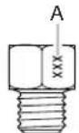
A. Size stamp or color
Use the following chart to find the exact orifice spud placement.
Remove choke from medium burner base.
Natural Gas Orifice Spud/Hood Chart
| Burner Rating | Color Size Burner Style | |
| 5,000 BTUs NG 5k | 1.01 mm Small burners | |
| Small burner bag | 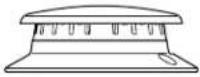 | |
15,000 BTUs No color 1.75 mm Medium burners
 | ||
| 20,000 BTUs Blue/ Yellow | 0.10 mm | Large burner - main |
| Black | 0.52 mm | Large burner - simmer |
- Place Propane gas orifice spuds in plastic parts bag for future use and keep with package containing literature.
NOTE: There may be extra orifices in your kit. - Replace the burner base.
- Replace burner cap.
- Repeat steps 2 through 8 for the remaining burners.
Complete Installation
- Refer to the "Make Gas Connection" section for properly connecting the cooktop to the gas supply.
- Refer to the "Electronic Ignition System" section for proper burner ignition, operation, and burner flame adjustments.
IMPORTANT: You may have to adjust the LO setting for each cooktop burner.
Checking for proper cooktop burner flame is very important. The small inner cone should have a very distinct blue flame 1/4" (6.4 mm) to 1/2" (13 mm) long. The outer cone is not as distinct as the inner cone. Propane gas flames have a slightly yellow tip.
- Refer to "Complete Installation" in the "Installation Instructions" section of these instructions to complete this procedure.
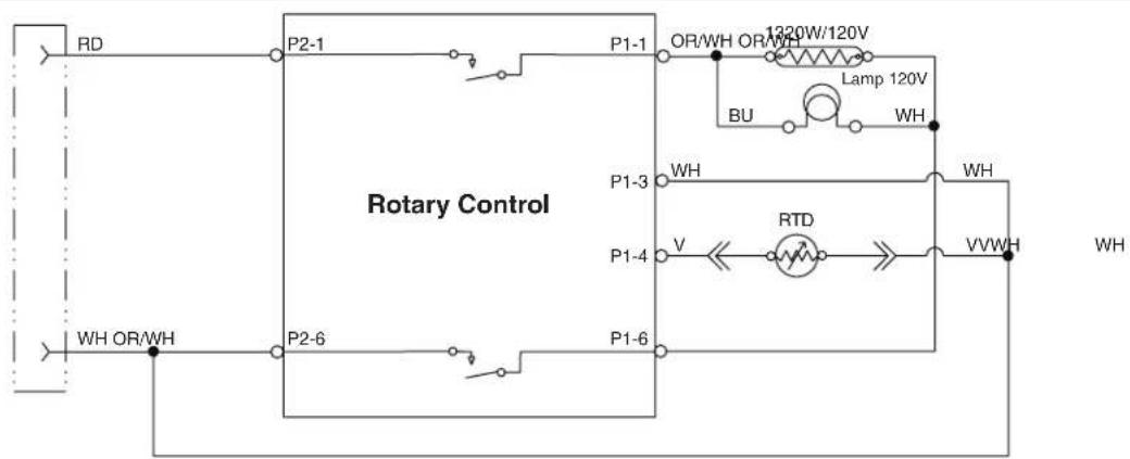
STRIP CIRCUITS
Griddle 120V Control Wiring Diagram to Cooktop Stand-Alone
flowchart
graph TD
    RD["RD"] --> P2-1["P2-1"]
    P2-1 --> P1-1["P1-1"]
    P1-1 --> OR["OR/WH OR/WH"]
    OR --> Lamp["Lamp 120V"]
    Lamp --> BW["WH"]
    BW --> Pump["WH"]
    Pump --> RTD["RTD"]
    RTD --> VV["V/VWH"]
    VV --> WH["WH"]
    P2-6["P2-6"]
    P1-6["P1-6"]
    P1-3["P1-3"]
    P1-4["P1-4"]
    P1-3 --> WH1["WH"]
    P1-4 --> V["V"]
    P2-6 --> OR2["OR/WH"]
    P1-6 --> OR3["OR/WH"]
    style P2-6 fill:#f9f,stroke:#333
    style P1-6 fill:#ccf,stroke:#333
    style P1-3 fill:#cfc,stroke:#333
    style P1-4 fill:#fcc,stroke:#333
    style P2-6 fill:#ffc,stroke:#333
    style P1-6 fill:#cfc,stroke:#333
    style P2-6 fill:#ffc,stroke:#333
    style P1-3 fill:#cfc,stroke:#333
    style P1-4 fill:#fcc,stroke:#333
    style P2-6 fill:#ffc,stroke:#333
    style P1-6 fill:#cfc,stroke:#333
    style P2-6 fill:#ffc,stroke:#333
    style P1-3 fill:#cfc,dasharray: 5 5
    style P1-4 fill:#fcc,dasharray: 5 5
    style P2-6 fill:#ffc,stroke:#333
    style P1-6 fill:#cfc,dasharray: 5 5
    style P2-6 fill:#ffc,stroke:#333
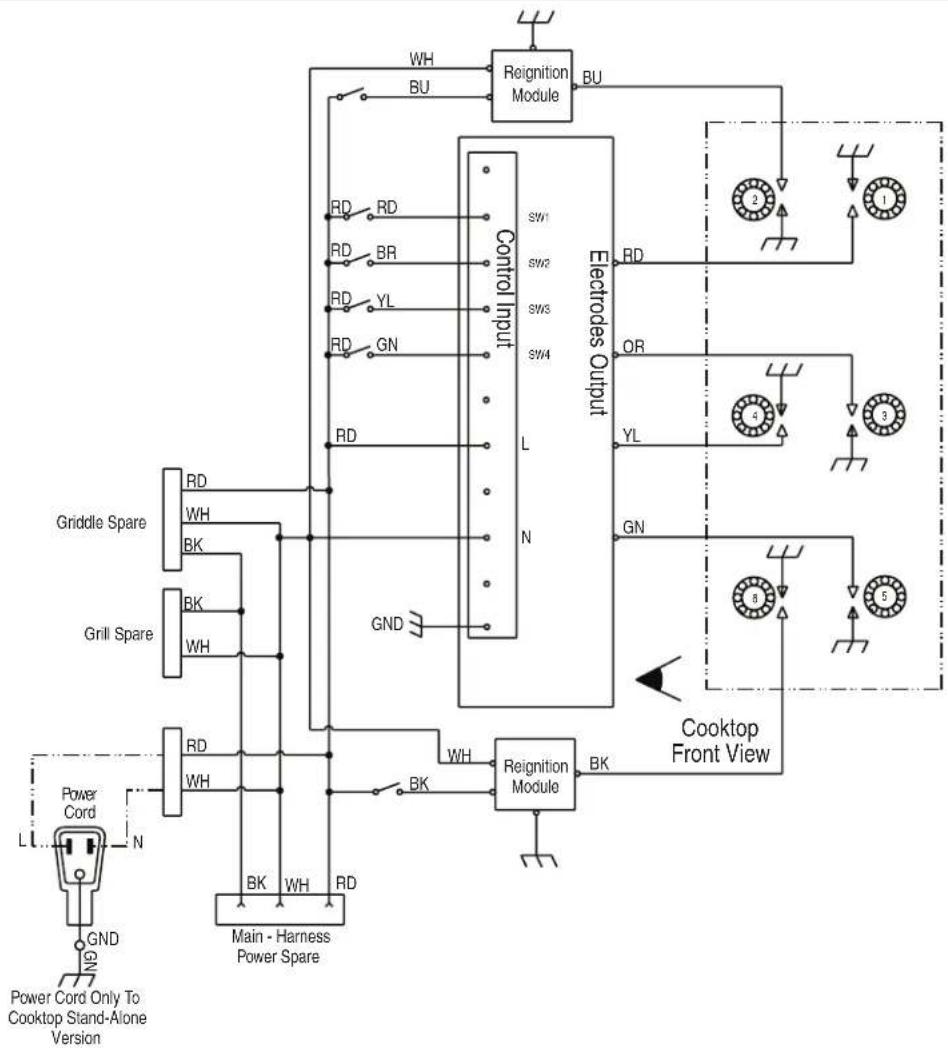
WIRING DIAGRAMS
Caution: Label all wires prior to disconnection when servicing controls. Wiring errors can cause improper and dangerous operation. Verify proper operation after servicing.
6-Burner Cooktop Reignition Wiring Diagram
flowchart
graph TD
    A["Power Cord"] --> B["GND"]
    B --> C["Main - Harness Power Spare"]
    C --> D["Griddle Spare"]
    D --> E["GBK"]
    E --> F["Control Input"]
    F --> G["Reignition Module"]
    G --> H["Reignition Module"]
    H --> I["Main - Harness Power Spare"]
    I --> J["Grill Spare"]
    J --> K["GBK"]
    K --> L["Control Input"]
    L --> M["Reignition Module"]
    M --> N["Reignition Module"]
    N --> O["Cooktop Front View"]
    O --> P["Control Input"]
    P --> Q["Reignition Module"]
    Q --> R["Reignition Module"]
    R --> S["Cooktop Front View"]
    S --> T["Main - Harness Power Spare"]
    T --> U["Grill Spare"]
    U --> V["GBK"]
    V --> W["Control Input"]
    W --> X["Reignition Module"]
    X --> Y["Reignition Module"]
    Y --> Z["Cooktop Front View"]
LEGEND
| Ground(Chassis) | Plug WithFemaleConnector | ReceptacleWith MaleConnector | Electrode Transformer Relay | Contacts | SolenoidValve | Switch CooktopGas Burner | RTD -TemperatureSensor | HeatingElement | Indicator Lamp | |
4-Burner Cooktop Reignition Wiring Diagram
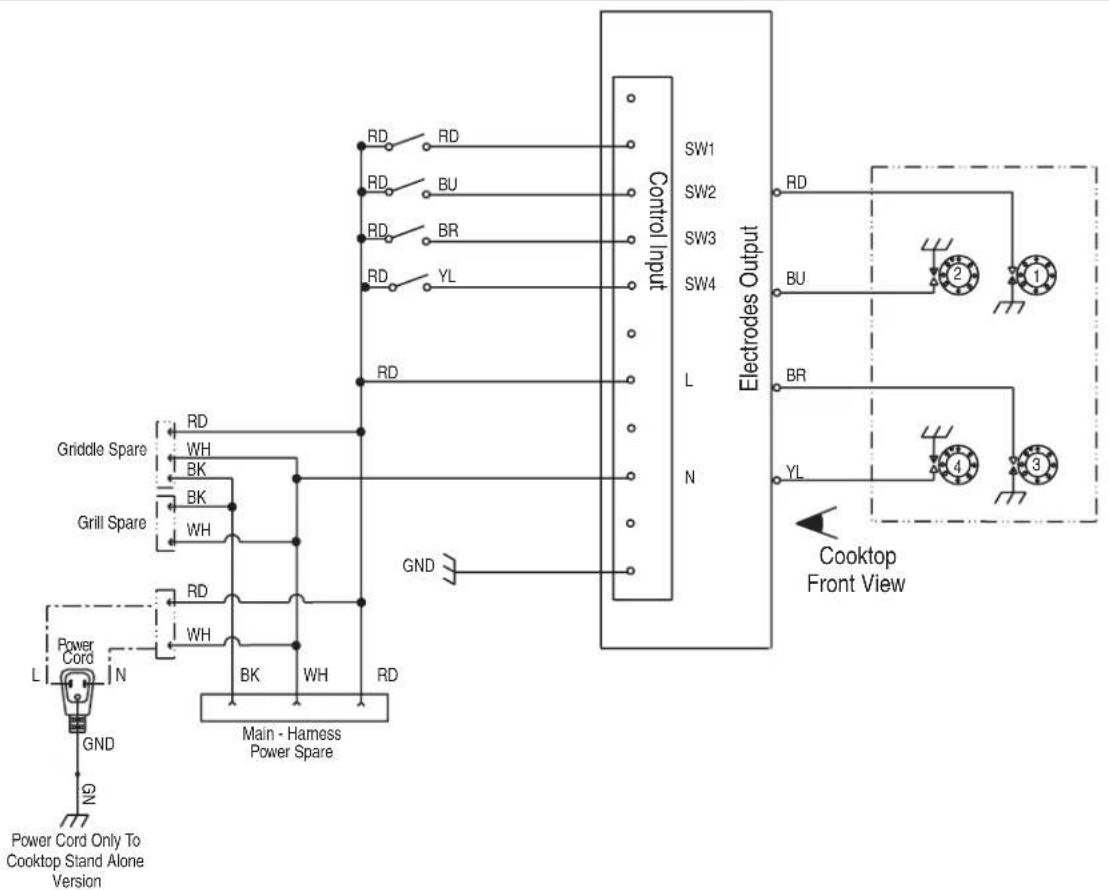
LEGEND
| Ground(Chassis) | Plug WithFemaleConnector | ReceptacleWith MaleConnector | Electrode Transformer Relay | Contacts | SolenoidValve | Switch CooktopGas Burner | RTD -TemperatureSensor | HeatingElement | Indicator Lamp | |
SÉCURITÉ DE LA TABLE DE CUISSON
A. Voir le tableau.
B. Voir le tableau.
C. Voir le tableau.
D. Voir le tableau.
E. Voir le tableau.
National Fire Protection Association
1 Batterymarch Park
Quincy, MA 02169-7471
CSA International
8501 East Pleasant Valley Road
Cleveland, Ohio 44131-5575
natural_image
Technical line drawing of a structural support frame with mounting holes and beam supports (no text or symbols)Raccordement au gaz
AVERTISSEMENT
Risque d'explosion
natural_image
Two technical diagrams labeled A and B showing layered structures with no visible text or symbols.A. Incorrect
B. Correct
A. Incorrect
B. Correct
(1) 本次股东大会的决议
(1) 本次股东大会的决议
A. Incorrect
B. Correct
natural_image
Diagram of a mechanical or electrical component with labeled parts A and B, showing layered structure without any text or symbols.natural_image
Simple line drawing of a mechanical or architectural component with no text or symbolsnatural_image
Line drawing of a mechanical device with labeled component A and directional arrow (no text or symbols beyond label)A. Vis de fixation de la console
natural_image
Technical line drawing of a hand holding a cable with a labeled component (B), alongside a separate view of a sleeveless sleeve (no text or symbols present)A
natural_image
Technical line drawing of a mechanical assembly with a cylindrical component and intersecting rods (no text or symbols)natural_image
Technical diagram of a mechanical component with labeled section A (no text or symbols present)natural_image
Simple line drawing of a boat hull with no text or symbolsnatural_image
Simple line drawing of a mechanical component or tool with no text or symbolsnatural_image
Line drawing of a mechanical device with labeled component A and directional arrow (no text or symbols beyond labels)A. Vis de fixation de la console
natural_image
Technical line drawing of a hand using a cable to install a component, with no visible text or symbolsA
natural_image
Line drawing of hands operating a mechanical device with pipes and components (no text or symbols)A
natural_image
Technical line drawing of a mechanical assembly with hoses and components (no text or symbols)B
natural_image
Technical diagram of a mechanical component with labeled section A (no text or symbols beyond label)B
natural_image
Technical diagram of a mechanical component with labeled section A (no text or symbols present)A. Chapeau de
l'ouverture d'accès