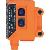
OJ5144 - Motion detector IFM - Free user manual and instructions
Find the device manual for free OJ5144 IFM in PDF.


| Product Type | Direct reflection motion detector with background suppression |
| Brand | IFM |
| Model | OJ5144 |
| Category | Motion detector |
| Technology | Optoelectronic (direct reflection cell) |
| Range | Up to 2 m (according to label, measured on white paper 200x200 mm) |
| Power supply | 10-30 V DC |
| Output | PNP or NPN programmable |
| Connection | 4 wires: BN (brown) = L+, BU (blue) = L-, BK (black) = output, WH (white) = programming |
| LED indication | Green: device operational; Yellow: switched output; Red: programming or fault |
| Programming functions | Setting with/without object, maximum range, electronic lock, output function |
| Mounting | Supplied mounting clip or side holes for screws |
| Housing material | Plastic |
| Weight | Approximately 50 g |
| Dimensions | Approximately 50 x 50 x 20 mm |
| Operating temperature | -25 °C to 60 °C |
| Protection rating | IP67 |
| Maintenance | Clean the lenses with a soft, dry cloth |
| Safety | Disconnect power before any electrical connection |
| General information | Manual available in several languages on notice-facile.com |
Frequently Asked Questions - OJ5144 IFM
User questions about OJ5144 IFM
0 question about this device. Answer the ones you know or ask your own.
Ask a new question about this device
Download the instructions for your Motion detector in PDF format for free! Find your manual OJ5144 - IFM and take your electronic device back in hand. On this page are published all the documents necessary for the use of your device. OJ5144 by IFM.
USER MANUAL OJ5144 IFM
Function and features
The diffuse reflection sensor detects objects and materials without contact and indicates their presence by a switched signal.
Range (r):
see type label (value referred to white paper 200mm× 200mm ).
Electrical connection
Isolate power, then connect the unit.
DC PNP DC NPN
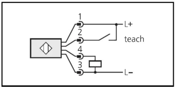
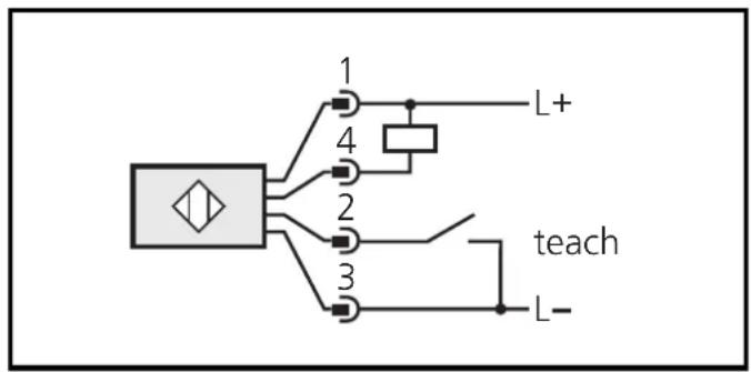
Core colours: BN = brown, BU = blue, BK = black, WH = white.
Programming of the output function by push button or programming wire (see page 12).
Installation
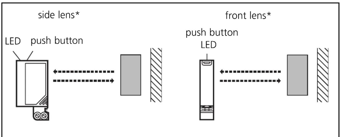
* In the following sections installation and set-up are described using the example of the type with front lens. The functions of the units with side lens are identical.
Align the photocell and fasten it to a mounting fixture.
Mounting of the series OJ51xx
The units of the OJ51xx series have two fixing holes on the side for mounting. A mounting fixture is not supplied.
Maximum range is only possible with precise alignment.
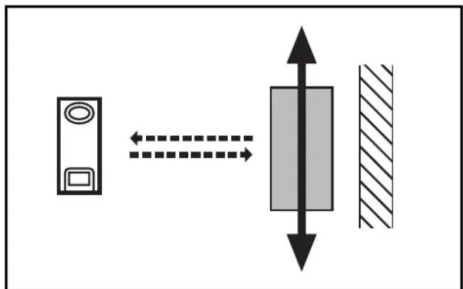
The objects to be detected are to move transversally to the lens of the
unit. In case of other directions of movement it should be tested before whether safe functioning is guaranteed.
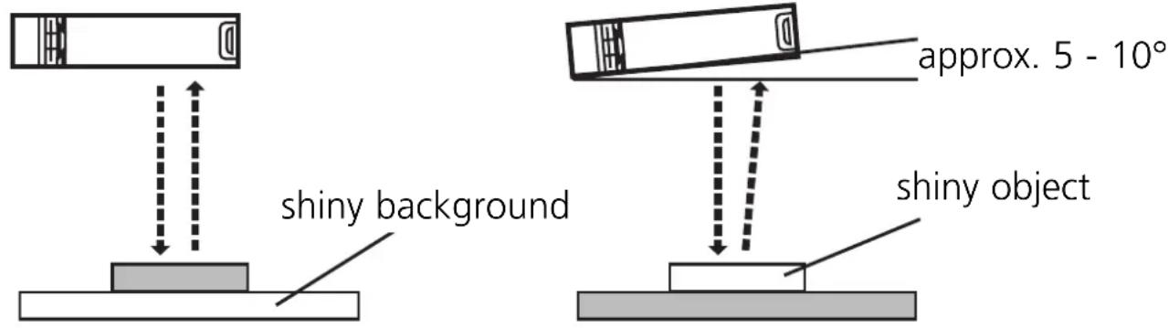
For demanding applications (small distance between the object and the background) we recommend the following mounting positions:
- In case of shiny background surfaces and less shiny object surfaces the sensor should be mounted vertically to the background surface.
- In case of shiny object surfaces and less shiny background surfaces the sensor should be mounted at an angle of approx. 5 - 10^ .
Installation of the supplied mounting fixture
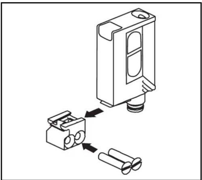
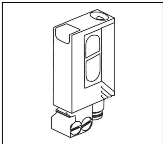
Secure the mounting fixture with the screws supplied, then slide the unit into the slot of the fixture until the spring clicks home.
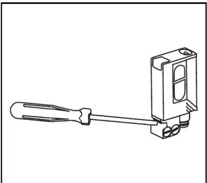
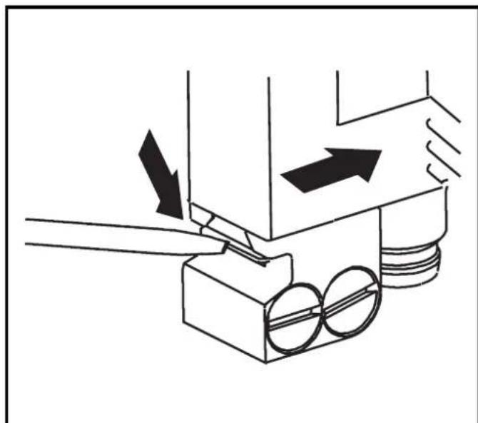
To remove the unit press the spring down with a screwdriver and slide the unit out.
Setting of the sensitivity with stationary objects*
| 1 | Activate the programming mode of the unit. Press for about 2s until the red LED flashes. |
| The red LED goes out; the yellow and green LEDs flash alternately. The unit is in the programming mode. |
| 2 | Setting with object. Press once. |
| The yellow and green LEDs go out for approx. 1s, then flash again alternately. |
| 3 | Setting without object. The background must be within the maximum range. Press once. |
| The yellow and green LEDs go out for approx. 1s, after approx. 3s the green LED is on. The unit is in the operating mode. |
You can also proceed in reverse order: first setting without the object, then with the object.
- The sensitivity can also be set in exactly the same way using the programming wire (pin 2 / WH). To activate the functions the programming wire is connected for the appropriate time to L+ (pin 1 / BN) for PNP units or to L- (pin 3 / BU) for NPN units. Feedback: If setting was not successful via the programming wire, the output will switch for 2s. The unit then reverts to the operating mode with the sensitivity unchanged.

If the setting of the sensitivity is not possible (e.g. object signal and background signal are about the same), the red LED flashes after step 3 for approx. 2s. The unit then passes into the operating mode with the sensitivity being unchanged.
If the setting button is not activated for 15 minutes during the programming process, the unit passes automatically into the operating mode with the sensitivity being unchanged.
Setting of the maximum sensitivity*
- Go into the programming mode (step 1).
- Align the unit so that no light is received by the object or the background (min. distance > max. range).
-
Press the setting button twice (see steps 2 and 3).
-
The maximum sensitivity can also be set in exactly the same way using the programming wire (pin 2 / WH). To activate the functions the programming wire is connected for the appropriate time to L+ (pin 1 / BN) for PNP units or to L- (pin 3 / BU) for NPN units.
Electronic lock
Activate the lock by connecting the programming wire for about 15s - 20s*.
De-activate the lock by connecting the programming wire again for 15s - 20s^* .
- To activate the functions the programming wire (pin 2 / WH) is connected to L+ (pin 1 / BN) for PNP units or to L- (pin 3 / BU) for NPN units for the appropriate time.
Programming the output function*

- The output function can be programmed in exactly the same way using the programming wire (pin 2 / WH). To activate the functions the programming wire is connected for the appropriate time to L+ (pin 1 / BN) for PNP units or to L- (pin 3 / BU) for NPN units.
Operation
Check the safe functioning of the unit. Display by LEDs.
| LED green is lit U | Unit is ready for operation. |
| LED yellow is lit O | Output is switched. |
| LEDs yellow + red | Flash alternately, 2 Hz: output short-circuited. Flash alternately, 1 Hz: internal malfunction (output is not switched). |
Maintenance
Keep the lens of the sensor free from soiling.
Brand : IFM
Model : OJ5144
Category : Motion detector