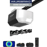
D2101C - Garage door CHAMBERLAIN - Free user manual and instructions
Find the device manual for free D2101C CHAMBERLAIN in PDF.

User questions about D2101C CHAMBERLAIN
0 question about this device. Answer the ones you know or ask your own.
Ask a new question about this device
Download the instructions for your Garage door in PDF format for free! Find your manual D2101C - CHAMBERLAIN and take your electronic device back in hand. On this page are published all the documents necessary for the use of your device. D2101C by CHAMBERLAIN.
USER MANUAL D2101C CHAMBERLAIN
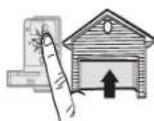
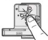
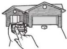
To register your garage door opener to receive updates and offers from Chamberlain, visit chamberlain.registria.com or use the icon below:
- Take a photo of the camera icon including the points
- Send it in by texting the photo to 71403 (US).

-933-PREMIUMMYD


- Please read this manual and the enclosed safety materials carefully!
- Fasten the manual near the garage door after installation.
- The door WILL NOT CLOSE unless the Protector System® is connected and properly aligned.
Periodic checks of the garage door opener are required to ensure safe operation. - The model number label is located on the back panel of your garage door opener.
- This garage door opener is compatible with myQ® and Security+ 2.0® accessories.
- DO NOT install on a one-piece door if using devices or features providing unattended close. Unattended devices and features are to be used ONLY with sectional doors.
Contents
Preparation 3
Assembly 7
Installation 11
Install the Door Control 22
Install the Protector System® 26
Connect Power 29
Adjustments 31
myQ App Control. 34
Connect With Your Smartphone
Operation. 38
Using your Garage Door Opener 35
Using your Door Control 36
Remote Control and Keyless Entry 37
Home Link. 37
Erase the Memory 38
To Open the Door Manually 38
Maintenance. 39
Troubleshooting 40
Warranty 42
Automatic Garage Door Opener Safety & Maintenance Guide 43
Repair Parts 45
Rail Assembly Parts 45
Installation Parts. 45
Model C2102C 46
Model C2405C 47
Model D2405C 47
Model C2202C 48
Model D2101C 49
Safety Symbol and Signal Word Review
This garage door opener has been designed and tested tooffer safe service provided it is installed, operated, maintained and tested in strict accordance with the instructions and warnings contained in this manual.
WARNING
Mechanical
WARNING
Electrical
When you see these Safety Symbols and Signal Words on the following pages, they will alert you to the possibility of serious injury or death if you do not comply with the warnings that accompany them. The hazard may come from something mechanical or from electric shock. Read the warnings carefully.
CAUTION
When you see this Signal Word on the following pages, it will alert you to the possibility of damage to your garage door and/or the garage door opener. If you do not comply with the cautionary statements that accompany it. Read them carefully.

WARNING: This product can expose you to chemicals including lead, which are known to the State of California to cause cancer or birth defects or other reproductive harm. For more information goto www.P65Warnings.ca.gov
Unattended Operation
The Timer-to-Close (TTC) feature, the myQ App, and myQ Garage Door and Gate Monitor are examples of unattended close and are to be used ONLY with sectional doors. Any device or feature that allows the door to close without being in the line of sight of the door is considered unattended close. The Timer-to-Close (TTC) feature, the myQ®App, and any other myQ devices are to be used ONLY with sectional doors.
The images throughout this manual are for reference only and your product may look different.
Preparation
Check the Door
WARNING
To prevent possible SERIOUS INJURY or DEATH:
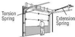
- ALWAYS call a trained door systems technician if garage door binds, sticks, or is out of balance. An unbalanced garage door may NOT reverse when required.
- NEVER try to loosen, move or adjust garage door, door springs, cables, pulleys, brackets or their hardware, ALL of which are under EXTREME tension.
- Disable ALL locks and remove ALL ropes connected to garage door BEFORE installation and operating garage door opener to avoid entanglement.
DO NOT install on a one-piece door if using devices or features providing unattended close Unattended devices and features are to be used ONLY with sectional doors.
CAUTION
To prevent damage to garage door and opener:
ALWAYS disable locks BEFOR Einstalling and operating the opener.
- ONLY operate garage door opener at 120V, 60 Hz to avoid malfunction and damage.
Before you begin:
- Disable locks and remove any ropes connected to the garage door.
- Lift the door half way up. Release the door. If balanced, it should stay in place, supported entirely by its springs.
- Raise and lower the door to check for binding or sticking. If your door binds, sticks, or is out of balance, call attained door systems technician.
- Checktheseal on thebottomof thedoor. Any gap between thefloor and the bottom of the door must not exceed 1/4'' (6 mm). Otherwise, the safety reversal system may not workproperly.
- Theopener should be installed above the center of the door. If thereis atorsion spring or center bearing platein theway of the header bracket, it may beinstalled within 4 feet (1.2 m) totheleft or right of thedoor center. See page 13.
Before You Connect with Your Smartphone
Monitor and control your garage door from anywhere using the myQ App. You will need a router with Wi-Fi® and a smartphone or other mobile device. Make sure your mobile device is connected to your Wi-Fi® network. Hold your mobile device in the place where your garage door opener will be installed and check the Wi-Fi® signal strength.
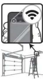
Check Signal Strength. If you see:


Wi-Fi signal is strong. You're all set! Install your new garage door opener.

Wi-Fi signal is weak.
The garage door opener will likely connect to your Wi-Fi network. If not, try one of the options below.
No Wi-Fi signal. Try one of the following:
- Move your router closer to the garage door opener to minimize interference from walls and other objects
Buy a Wi-Fi range extender
Visit support.chamberlaingroup.com for more details.
See my App Control page 37 to connect your garage door opener to your Wi-Fi network.
Preparation
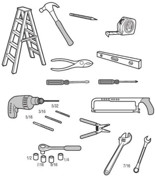
Tools Needed
Additional Items You May Need:
Survey your garage are a to see if you will need any of the following items:
(2)2X4 Pieces of wood : May beused to fasten the header bracket to the structural supports. Also used to position the garage door opener during installation and for testing the safety reversing sensors.
- Support bracket and fastening hardware: Must beused if you have a finished ceiling in your garage.
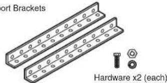
Support Brackets
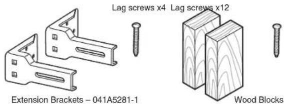
- Extension brackets (Model 041A5281-1) or wood blocks: Depending upon garage construction, extension brackets or wood blocks may be needed to install the safety reversing sensor.
- Fastening hardware: Alternate floor mounting of the safety reversing sensor will require hardware not provided.
Doorreforcement: Required if you have alight weight steel, aluminum, fiber glass or glass panel door. - Rail extension kit: Required if your garage door is more than 7 feet (2.13 m) high.
Preparation
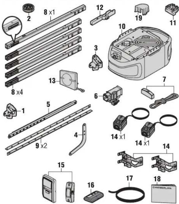
Carton Inventory
Save the carton and packing material until the installation and adjustment is complete. Instructions for the accessories will be attached to the accessory and are not included in this manual. The images throughout this manual are for reference only and your product may look different.
- Header bracket
- Pulley
- Door bracket
- Curved door arm
- Straight door arm (Packaged inside front
- Trolley
- Emergency release rope and handle
- Rail (1 front and 4 center sections)
- Hanging brackets (2)
(Packaged inside the front rail section) - Garage door opener (motor unit)
- Chain spreader with screws - Model C2405
- "U" bracket
- Chain and cable or chain (D2405C and D21202C only)
- The Protector System® Safety reversing sensors with 2 conductor white and white/black wire attached: sending sensor (1), receiving sensor (1), and safety sensor brackets (2)
- Remote control
- Push Button Door Control - Models C2202C, D2101C, C2102C
Multi-Function Control Panel - Model C2405C, D2405C - White and red/white wire
- Installation manual and all warning labels
- Sprocket cover - Model C2405C, D2405C
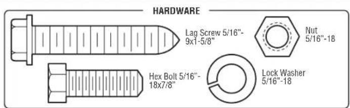
See Hard ware page 6.
Goto chamberlain.com for replacement or additional accessories:
3-button remote control model 953EV-P2
Wireless keypad model 940EV-P2
Preparation
Hardware
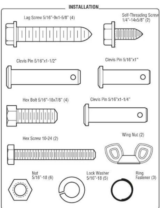
Assembly
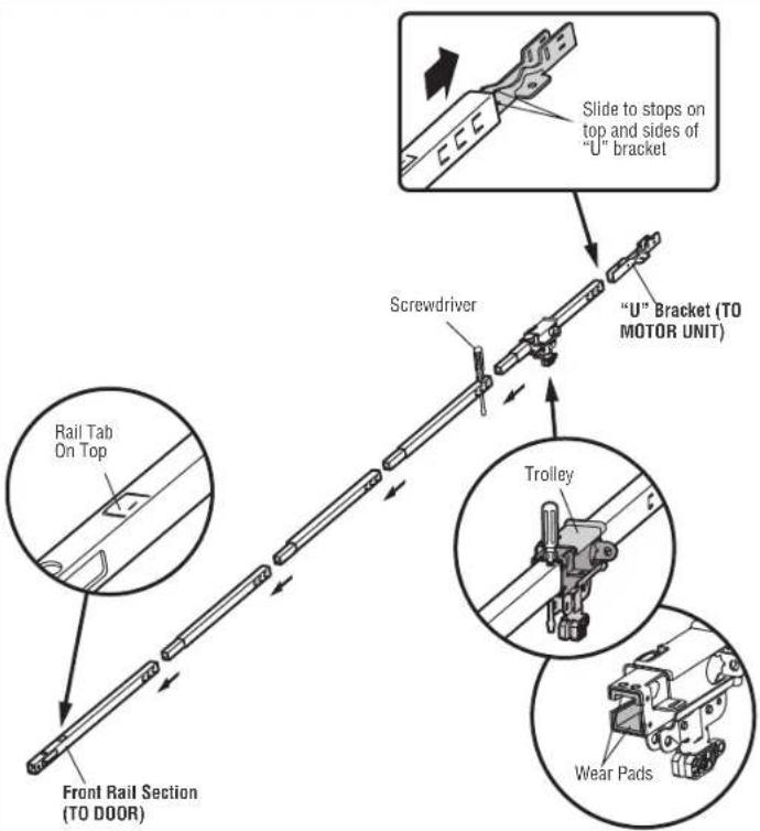
STEP1 Assemble the Rail and Install the Trolley

CAUTION
To prevent INJURY from pinching, keep hands and fingers away from the joints while assembling the rail.
To avoid installation difficulties, do not run the garage door opener until instructed to do so. The front rail has acut out "window" at the door end. The rail tab MUST be on top of the rail when assembled.
- Remove the straight door arm and hanging bracket packaged inside the front rail and set a side for Installation Step 5 and 9. NOTE: To prevent INJURY while unpacking the rail carefully remove the straight door arm stored within the rail section.
- Align theiral sections on aflat surface as shown and slide the tapered ends into the larger ones. Tabs along the side will lock into place.
- Place the motor unit on packing material to protect the cover, and rest the backend of the rail on top. For convenience, put a support under the front end of the rail.
- As a temporary stop, insert a screwdriver into the hole in the second rail section from the motor unit, as shown.
- Check to be sure there are 4 plastic wear pads inside the inner trolley. If they became loose during shipping, checkall packing material. Snap them back into position as shown
- Slide the trolley assembly toward the screwdriver as shown.
- Slide the rail onto the "U" bracket, until it reaches all the stops on the top and sides of the "U" bracket.
Assembly
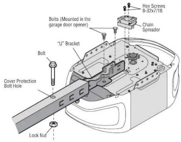
STEP 2 Fasten the Rail to the Motor Unit MODEL C2405

CAUTION
To avoid SERIOUS damage to garage door opener, use ONLY those bolts/fasteners mounted in the top of the opener.
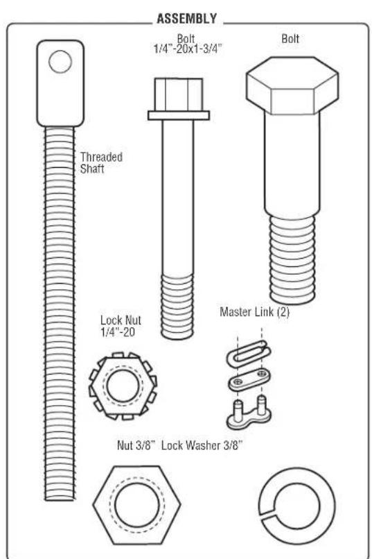
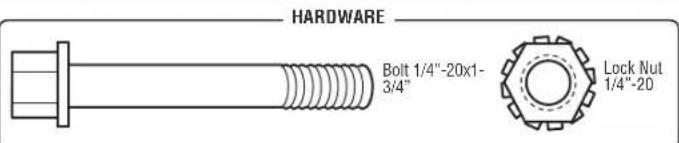
- Insert a1/4"-20 x 1-3/4" bolt into the cover protection bolt hole on the backend of the rail as shown. Tighten securely with a1/4"-20 lock nut. DO NOT over tighten.
- Remove the bolts from the top of the motor unit.
- Use the carton to support the front end of the rail.
- Place the "U" bracket, flat side down onto the motor unit and align the bracket holes with the bolt holes.
- Fasten the "U" bracket with the previously removed bolts; DO NOT use any power tools. The use of power tools may permanently damage the garage door opener.
- Attach chain spreader to the motor unit with two screws.
Assembly
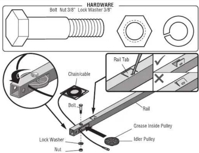
STEP 3 Install the Idler Pulley
- Lay the chain/cable beside the rail, as shown. Grasp the end of the cable and pass approximately 12^ (30 cm) of cable through the window. Allow it to hang until Assembly Step 4.
- Remove the tape from the idler pulley. The inside center should be pre-greased. If dry, regrase to ensure proper operation.
- Place the idler pulley into the window as shown.
- Insert the idler bolt from the top through the rail and pulley. Tighten with a 3/8'' lock washer and nut underneath the rail until the lock washer is compressed.
- Rotate the pulley to be sure it spins freely.
- Locate the rail tab. The rail tab is near the idler pulley on the front rail section. Use a flat head screwdriver and lift the rail tab until the tab is vertical (90°).
Assembly
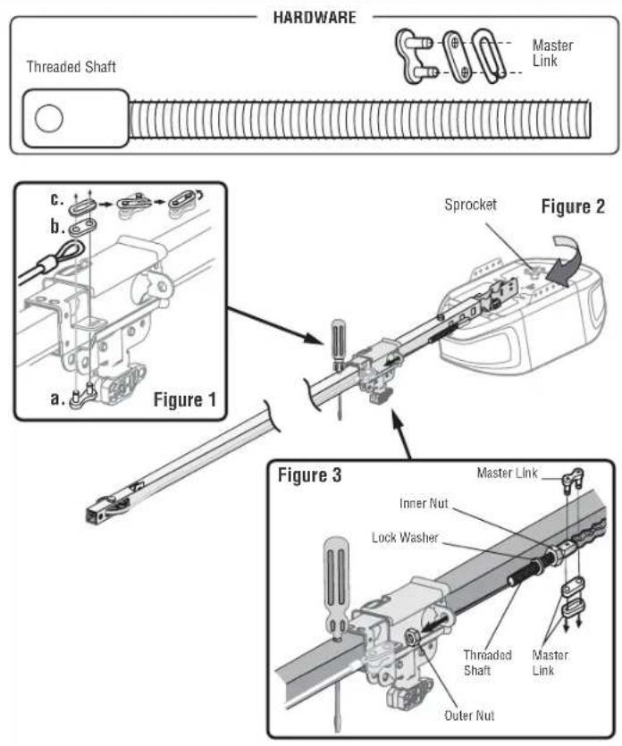
STEP 4 Install the Chain
- Pull the cable around the idler pulley and toward the trolley.
- Connect the cable to theretaining slot on the trolley, as shown. (Figure1)
a. Push pins of master linkbar through cablelinkand trolley slot.
b. Push master linkcap over pins and past pin notches.
c. Slide the closed end of the clip-on spring over one of the pins.
Push the open end of the clip-on spring onto - With the trolley against the screwdriver, dispense the remainder of the cable/chain along the rail toward the motor unit around the sprocket and continuing to the trolley assembly. The sprocket teeth must engage the chain. (Figure 2)
- Check to make sure the chain is not twisted, then connect it to the threaded shaft with the remaining master link.
- Thread the inner nut and lock washer onto the trolley threaded shaft.
- Insert the trolley threaded shaft through the hole in the trolley. Be sure the chain is not twisted. (Figure 3)
- Loosely thread theouter nut ontothetrolley threaded shaft.
- Remove the screwdriver.
Assembly
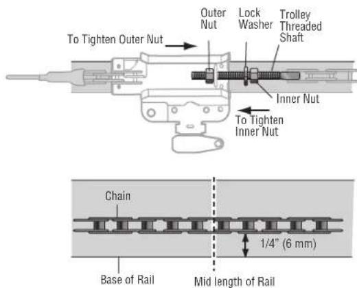
STEP 5 Tighten the Chain
- Spin the inner nut and lock washer down the trolley threaded shaft, away from the trolley.
- To tighten the chain, turn the outer nut in the direction shown
- When the chain is approximately 1/4'' (6 mm) above the base of the rail at its midpoint, reighten the inner nut to secure the adjustment.
Sprocket noise can result if the chain is too loose. When installation is complete, you may notice some chain droop with the door closed. This is normal. If the chain returns to the position shown when the door is open, do not re-adjust the chain.
NOTE: During future maintenance, ALWAYS pull the emergency release handle to disconnect the trolley before adjusting the chain.
Installation
IMPORTANT INSTALLATION INSTRUCTIONS
WARNING
To reduce the risk of SEVERE INJURY or DEATH:
- READ AND FOLLOW ALL INSTALLATION WARNINGS AND INSTRUCTIONS.
- Install garage door opener ONLY on properly balanced and lubricated garage door. An improperly balanced door may NOT reverse when required and could result in SEVERE INJURY or DEATH.
- ALL repairs to cables, spring assemblies and other hardware MUST be made by a trained door systems technician BEFORE installing opener.
- Disable ALL locks and remove ALL ropes connected to garage door BEFORE installing opener to avoid entanglement.
- Where possible, install the door opener 7 feet (2.13 m) or more above the floor.
- Mount the emergency release within reach, but at least 6 feet (1.83 m) above the floor and avoiding contact with vehicles to avoid accidental release.
- NEVER connect garage door opener to power source until instructed to do so.
-
NEVER wear watches, rings or loose clothing while installing or servicing opener. They could be caught in garage door or opener mechanisms.
-
Install wall-mounted garage door control:
within sight of the garage door.
out of reach of small children at a minimum height of 5 feet (1.5 m) above floors, landings, steps or any other adjacent walking surface.
away from ALL moving parts of the door.
-
Place entrapment warning label on wall next to garage door control in a prominent location.
-
Place emergency release/safety reverse test label in plain view on inside of garage door.
- Upon completion of installation, test safety reversal system. Door MUST reverse on contact with a 1 - 1 / 2^n (3.8 cm) high object (or a 2x4 laid flat) on the floor.
- DO NOT install on a one-piece door if using devices or features providing unattended close.
Unattended devices and features are to be used ONLY with sectional doors.
14. SAVE THESE INSTRUCTIONS.
Installation
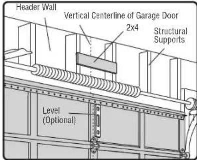
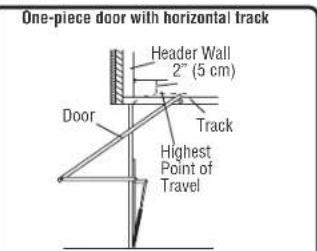
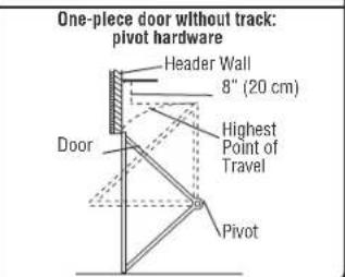
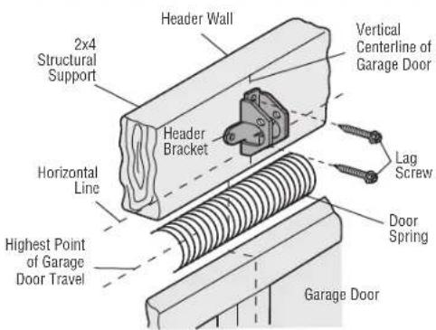
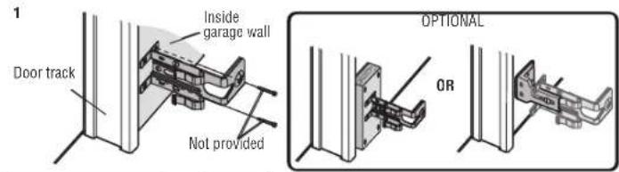
STEP 1 Determine theHeader Bracket Location
WARNING
To prevent possible SERIOUS INJURY or DEATH:
- Header bracket MUST be RIGIDLY fastened to structural support on header wall or ceiling, otherwise garage door might NOT reverse when required. DO NOT install header bracket over drywall.
Concrete anchors MUST be used if mounting header bracket or 2x4 into masonry. - NEVER try to loosen, move or adjust garage door, springs, cables, pulleys, brackets, or their hardware, ALL of which are under EXTREME tension.
- ALWAYS call a trained door systems technician if garage door binds, sticks, or is out of balance. An unbalanced garage door might NOT reverse when required.
Installation procedures vary according to garage door types. Follow the instructions which apply to your door.
1. Close the door and mark the inside vertical centerline of the garage door.
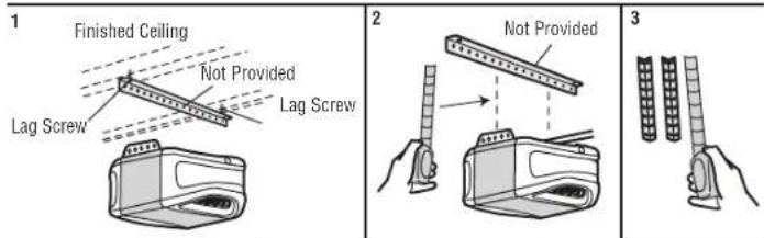
2. Extend the line onto the header wall above the door. You can fasten the header bracket within 4 feet (1.22 m) of the left or right of the door center only if a torsion spring or center bearing plate is in the way; or you can attach it to the ceiling (see page T6) when clearance is minimal. (It may be mounted on the wall upside down if necessary, to gain approximately 1/2^* (1 cm). If you need to install the header bracket on a 2x4 (on wall or ceiling), use lag screws (not provided) to securely fasten the 2x4 to structural supports as shown here and on page 16.
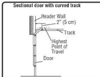
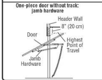
3. Open your door to the highest point of travel as shown. Draw an intersecting horizontal line on the header wall 2^ (5 cm) above the high point:
- 2^ (5 cm) above the high point for sectional door and one-piece door with track.
- 8^ (20 cm) above the high point for one-piece door without track.
This height will provide travel clearance for the top edge of the door. NOTE: If the total number of inches exceeds the height available in your garage, use the maximum height possible, or refer to page 16 for ceiling installation.
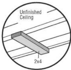
OPTIONAL CEILING MOUNT FOR HEADER BRACKET
Installation
STEP 2 Install the Header Bracket
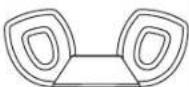
You can attach the header bracket either to the wall above the garage door, or to the ceiling. Follow the instructions which will work best for your particular requirements. Do not install the header bracket over drywall. If installing into masonry, use concrete anchors (not provided).
OPTION A - WALL INSTALLATION
- Center the bracket on the vertical centerline with the bottom edge of the bracket on the horizontal line as shown (with the arrow pointing toward the ceiling).
- Mark the vertical set of bracket holes. Drill 3/16^ pilot holes and fasten the bracket securely to a structural support with the hardware provided.
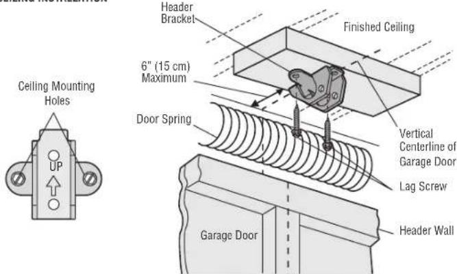
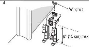
OPTION B - CEILING INSTALLATION
- Extend the vertical centerline onto the ceiling as shown.
- Center the bracket on the vertical mark, no more than 6^ (15 cm) from the wall. Make sure the arrow is pointing away from the wall. The bracket can be mounted flush against the ceiling when clearance is minimal.
- Mark the side holes. Drill 3/16'' pilot holes and fasten bracket securely to a structural support with the hardware provided.
WALL INSTALLATION
CEILING INSTALLATION
Installation
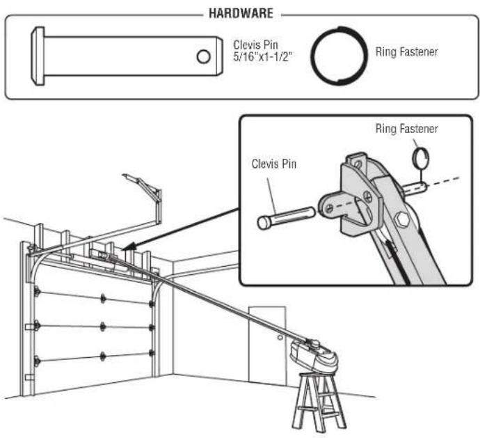
STEP 3 Attach the Rail to the Header Bracket
- Position the opener on the garage floor below the header bracket. Use packing material as a protective base.
NOTE: If the door spring is in the way, you will need help. Have someone hold the opener securely on a temporary support to allow the rail to clear the spring.
- Position the rail bracket against the header bracket.
- Align the bracket holes and join with a clevis pin as shown.
- Insert a ring fastener to secure.
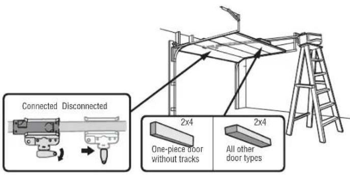
STEP 4 Position the Garage Door Opener
CAUTION
To prevent damage to garage door, rest garage door opener rail on 2x4 placed on top section of door.
- Remove the packing material and lift the garage door opener onto a ladder.
- Fully open the door and place a 2x4 (laid flat) under the rail. For one-piece doors without tracks, lay the 2x4 on its side.
NOTE: A 2x4 is ideal for setting the distance between the rail and the door. If the ladder is not tall enough you will need help at this point. If the door hits the trolley when it is raised, pull the trolley release arm down to disconnect the inner and outer trolley. Slide the outer trolley toward the garage door opener. The trolley can remain disconnected until instructed.
Installation
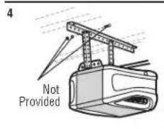
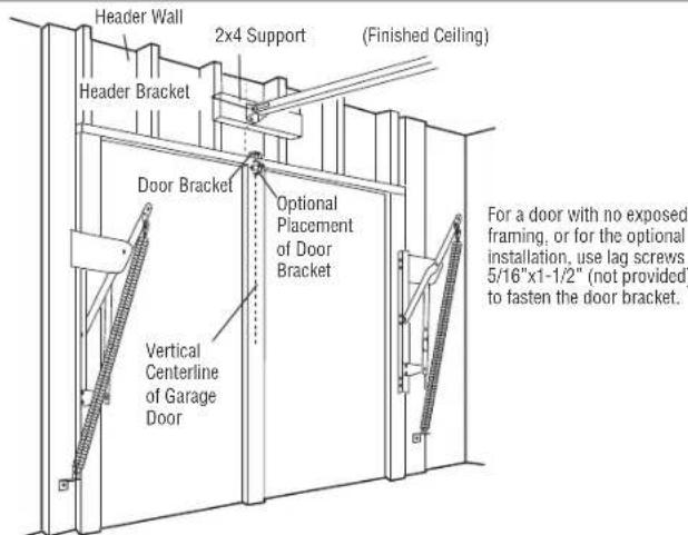
STEP 5 Hang the Garage Door Opener
WARNING
To avoid possible SERIOUS INJURY from a falling garage door opener, fasten it SECURELY to structural supports of the garage. Concrete anchors MUST be used if installing ANY brackets into masonry.
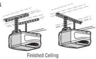
Hanging the garage door opener will vary depending on your garage. Below are three example installations. Your installation may be different. For ALL installations the garage door opener MUST be connected to structural supports. The instructions illustrate one of the examples below.
1. On finished ceilings, use the lag screws to attach a support bracket (not provided) to the structural supports before installing the garage door opener.
2. Make sure the garage door opener is aligned with the header bracket. Measure the distance from each side of the garage door opener to the support bracket.
3. Cut both pieces of the hanging bracket to required lengths.
4. Attach the end of each hanging bracket to the support bracket with appropriate hardware (not provided).
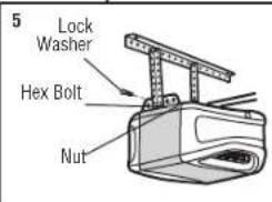
5. Attach the garage door opener to the hanging brackets with the hex bolts, lock washers, and nuts.
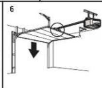
6. Remove the 2x4 and manually close the door. If the door hits the rail, raise the header bracket.
EXAMPLES
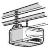
Unfinished Ceiling
Installation
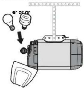
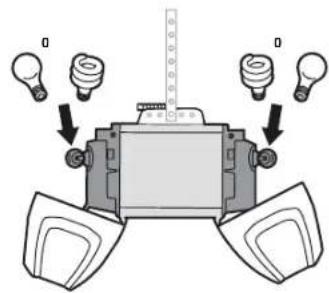
STEP 6 Install the Light Bulbs
CAUTION
To prevent possible OVERHEATING of the end panel or light socket:
Use ONLY A19 light bulbs.
DO NOT use incandescent bulbs larger than 100W.
DO NOT use compact fluorescent light bulbs larger than 26W (100W equivalent).
DO NOT use halogen bulbs.
DO NOT use short neck or specialty light bulbs.
LED bulbs may cause remote control radio interference. Use ONLY LED bulbs
recommended here:chamberlain.com/bulb.
- Pull light lens down.
- Insert light bulb
- Closelight lens
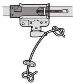
STEP 7 Attach the Emergency Release Rope and Handle
WARNING
To prevent possible SERIOUS INJURY or DEATH from a falling garage door:
-
If possible, use emergency release handle to disengage trolley ONLY when garage door is CLOSED. Weak or broken springs or unbalanced door could result in an open door falling rapidly and/or unexpectedly.
NEVER use emergency release handle unless garage doorway is clear of persons and
obstructions.
NEVER use handle to pull door open or closed. If rope knot becomes untied, you could fall. -
Insert one end of the emergency release rope through the handle. Make sure that "NOTICE" is right side up. Secure with an overhand knot at least 1" (2.5 cm) from the end of the rope to prevent slipping.
- Insert the other end of the emergency release rope through the hole in the trolley release arm. Mount the emergency release within reach, but at least 6 feet (1.83 m) above floor, avoiding contact with vehicles to prevent accidental release and secure with an overhand knot.
NOTE: If it is necessary to cut the emergency release rope, seal the cut end with a match or lighter to prevent unraveling. Ensure the emergency release rope and handle are above the top of all vehicles to avoid entanglement.
Installation
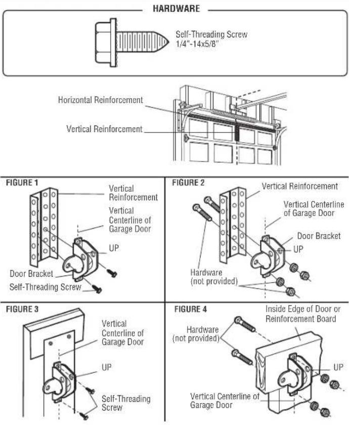
STEP 8 Install the Door Bracket
CAUTION
Fiberglass, aluminum or lightweight steel garage doors WILL REQUIRE reinforcement BEFORE installation of door bracket. Contact the garage door manufacturer or installing dealer for opener reinforcement instructions or reinforcement kit. Failure to reinforce the top section as required according to the door manufacturer may void the door warranty.
A horizontal and vertical reinforcement is needed for lightweight garage doors (fiberglass, aluminum, steel, doors with glass panel, etc.) (not provided). A horizontal reinforcement brace should be long enough to be secured to two or three vertical supports. A vertical reinforcement brace should cover the height of the top panel. Contact the garage door manufacturer or installing dealer for opener reinforcement instructions or reinforcement kit.
NOTE: Many door reinforcement kits provide for direct attachment of the elevis pin and door arm. In this case you will not need the door bracket; proceed to the next step.
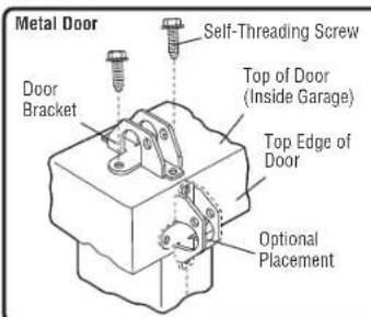
OPTION A - SECTIONAL DOORS
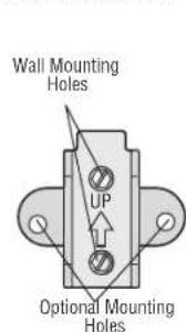
- Center the door bracket on the previously marked vertical centerline used for the header bracket installation. Note correct UP placement, as stamped inside bracket.
- Position the top edge of the bracket 2"-4" (5-10 cm) below the top edge of the door, OR directly below any structural support across the top of the door.
- Mark, drill holes and install as follows, depending on your door's construction.
Metal or light weight doors using a vertical angle Iron brace In the door panel support and the door bracket:
-
Drill 3/16^ fastening holes. Secure the door bracket using the two 1/4^ - 14x5/8^ self-threading screws. (Figure 1)
-
Alternately, use two 5 / 16^ - 18x2^ bolts, lock washers and nuts (not provided). (Figure 2)
Metal, insulated or light weight factory reinforced doors:
- Drill 3 / 16^ fastening holes. Secure the door bracket using the self-threading screws. (Figure 3)
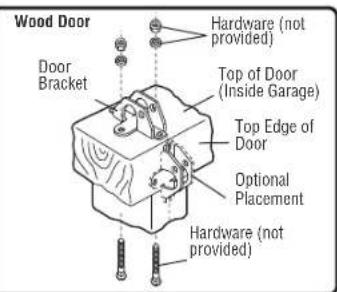
Wood doors:
- Use top and bottom or side door bracket holes. Drill 5/16" holes through the door and secure bracket with 5/16" - 18x2" carriage bolts, lock washers and nuts (not provided). (Figure 4)
NOTE: The 1/4"-14x5/8" self-threading screws are not intended for use on wood doors.
Installation
STEP 8 Install the Door Bracket (continued)
OPTION B - ONE-PIECE DOORS
- Center the door bracket on the top of the door, in line with the header bracket as shown.
- Mark either the left and right, or the top and bottom holes.
Metal Doors:
- Drill 3/16" pilot holes and fasten the bracket with the self-threading screws provided.
Wood Doors:
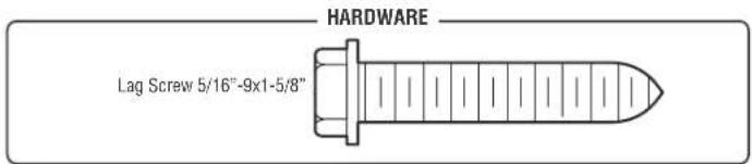
- Drill 5 / 16^ holes and use 5 / 16^ - 18x2^ carriage bolts, lock washers and nuts (not provided) or 5 / 16^ 1 - 1 / 2^ lag screws (not provided) depending on your installation needs.
NOTE: The door bracket may be installed on the top edge of the door if required for your installation. (Refer to the dotted line optional placement drawing.)
Installation
STEP 9 Connect the Door Arm to the Trolley
Installation will vary according to the garage door type. Follow the instructions which apply to your door.
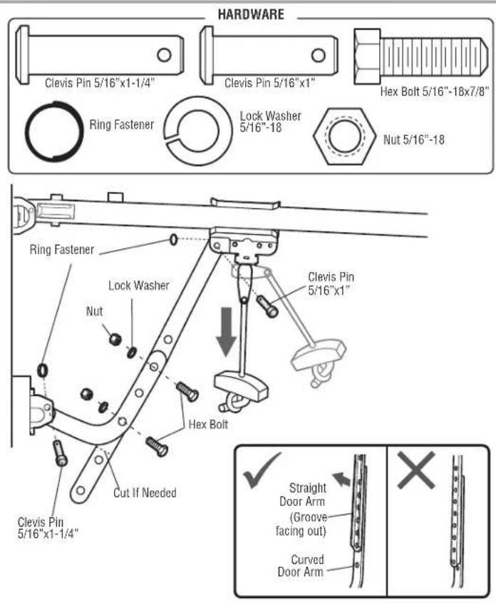
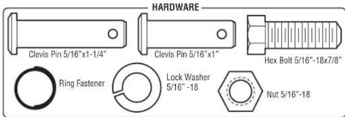
OPTION A - SECTIONAL DOORS
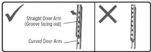
IMPORTANT: The groove on the straight door arm MUST face away from the curved door arm.
- Close the door. Disconnect the trolley by pulling the emergency release handle.
- Attach the straight door arm to the outer trolley using the clevis pin. Secure with the ring fastener.
- Attach the curved door arm to the door bracket using the clevis pin. Secure with the ring fastener.
- Bring arm sections together. Find two pairs of holes that line up and join sections. Select holes as far apart as possible to increase door arm rigidity and attach using the bolts, nuts, and lock washers.
- Pull the emergency release handle toward the garage door opener until the trolley release arm is horizontal. The trolley will re-engage automatically when the garage door opener is activated.
NOTE: If the holes in the curved door arm and the straight door arm do not align, reverse the straight door arm, select two holes (as far apart as possible) and attach using bolts, nuts, and lock washers. If the straight door arm is hanging down too far, you may cut 6^ (15 cm) from the solid end.
Installation
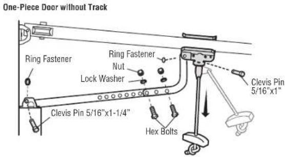
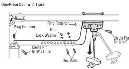
STEP 9 Connect the Door Arm to the Trolley (continued) OPTION B - ONE-PIECE DOORS
IMPORTANT: The groove on the straight door arm MUST face away from the curved door arm. 1. Close the door. Disconnect the trolley by pulling the emergency release handle.
- Fasten the straight door arm and the curved door arm together to the longest possible length (with a 2 or 3 hole overlap) using the bolts, nuts, and lock washers.
- Attach the straight door arm to the door bracket using the clevis pin. Secure with the ring fastener.
- Attach the curved door arm to the trolley using the clevis pin. Secure with the ring fastener.
- Pull the emergency release handle toward the garage door opener until the trolley release arm is horizontal.
Installation
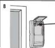
STEP 10 Install the Door Control PUSH BUTTON DOOR CONTROL
WARNING
To prevent possible SERIOUS INJURY or DEATH from electrocution:
- Be sure power is NOT connected BEFORE installing door control.
- Connect door control ONLY to 12 VOLT low voltage wires.
To prevent possible SERIOUS INJURY or DEATH from a closing garage door:
- Install door control within sight of garage door, out of reach of small children at a minimum height of 5 feet (1.5 m) above floors, landings, steps or any other adjacent walking surface, and away from ALL moving parts of door.
- NEVER permit children to operate or play with door control push buttons or remote control transmitters.
- Activate door ONLY when it can be seen clearly, is properly adjusted, and there are no obstructions to door travel.
- ALWAYS keep garage door in sight until completely closed. NEVER permit anyone to cross path of closing garage door.
INTRODUCTION
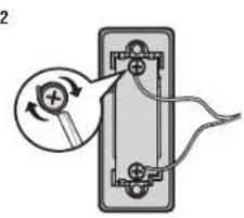
Install the door control within sight of the door at a minimum height of 5 feet (1.5 m) above floors, landings, steps or any other adjacent walking surface, where small children cannot reach, and away from the moving parts of the door.
NOTE: Your product may look different than the illustrations.
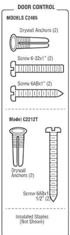
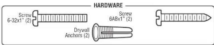
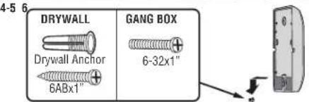
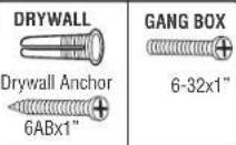
HARDWARE
Screw 6ABx1-1/2" (2)
Drywall Anchors (2)
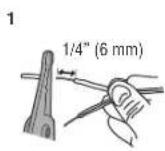
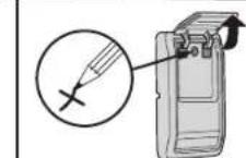
- Strip 1/4" (6 mm) of insulation from one end of the wire and separate the wires.
- Connect one wire to each of the two screws on the back of the door control. The wires can be connected to either screw.
- Mount the door control with the hardware provided.
Installation
MULTI-FUNCTION CONTROL PANEL


WARNING
To prevent possible SERIOUS INJURY or DEATH from electrocution:
- Be sure power is NOT connected BEFORE installing door control.
- Connect door control ONLY to 12 VOLT low voltage wires.
To prevent possible SERIOUS INJURY or DEATH from a closing garage door:
- Install door control within sight of garage door, out of reach of small children at a minimum height of 5 feet (1.5 m) above floors, landings, steps or any other adjacent walking surface, and away from ALL moving parts of door.
- NEVER permit children to operate or play with door control push buttons or remote control transmitters.
- Activate door ONLY when it can be seen clearly, is properly adjusted, and there are no obstructions to door travel.
- ALWAYS keep garage door in sight until completely closed. NEVER permit anyone to cross path of closing garage door.
INTRODUCTION
Older Chamberlain door controls and third party products are not compatible. Install door control within sight of garage door, out of reach of small children at a minimum height of 5 feet (1.5 m) above floors, landings, steps or any other adjacent walking surface, and away from ALL moving parts of door. For gang box installations it is not necessary to drill holes or install the drywall anchors. Use the existing holes in the gang box.
NOTE: Your product may look different than the illustrations.
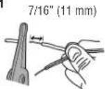
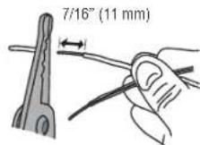
- Strip 7/16" (11 mm) of insulation from one end of the wire and separate the wires.
- Connect one wire to each of the two screws on the back of the door control. The wires can be connected to either screw. If your garage is pre-wired for the door control choose any two wires to connect, note which wires are used so the correct wires are connected to the garage door opener in a later step.
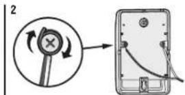
- Mark the location of the bottom mounting hole and drill a 5 / 32^ hole.
- Install the bottom screw, allowing 1/8^ (3 mm) to protrude from the wall.
- Position the bottom hole of the door control over the screw and slide down into place.
- Lift the push bar up and mark the top hole.
- Remove the door control from the wall and drill a 5/32" hole for the top screw.
- Position the bottom hole of the door control over the screw and slide down into place. Attach the top screw.
1
4-
Installation
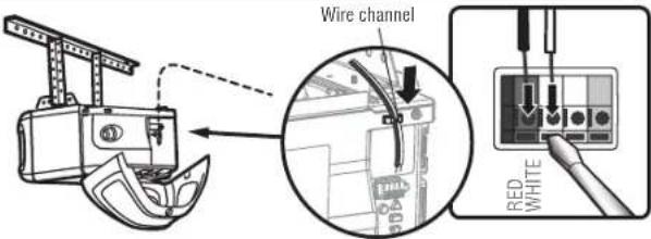
STEP 11 Wire the Door Control to the Garage Door Opener
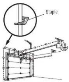
- Run the white and red/white wire from the door control to the garage door opener. Attach the wire to the wall and ceiling with the staple (not applicable for gang box or pre-wired installations). Do not pierce the wire with the staple as this may cause a short or an open circuit.
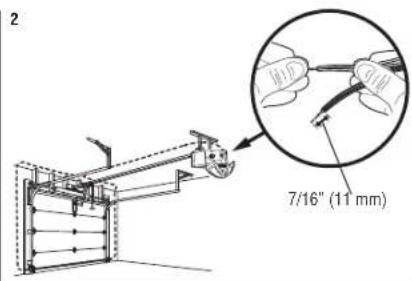
- Strip 7/16" (11 mm) of Insulation from the end of the wire near the garage door opener.
- Connect the wire to the red and white terminals on the garage door opener. If your garage is pre-wired make sure you use the same wires that are connected to the door control. To insert or release wires from the terminal, push in the tab with screwdriver tip.
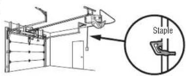
HARDWARE
Insulated Staple (Not Shown)
1
1
3
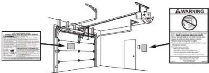
STEP 12 Attach the Warning Labels
- Attach the entrapment warning label on the wall near the door control with tacks or staples.
- Attach the manual release/safety reverse test label in a visible location on the inside of the garage door.
Installation
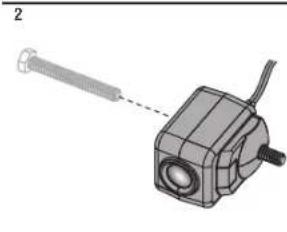
STEP 13 Install the Protector System
WARNING
Be sure power is NOT connected to the garage door opener BEFORE installing the safety reversing sensor. To prevent SERIOUS INJURY or DEATH from closing garage door:
- Correctly connect and align the safety reversing sensor. This required safety device MUST NOT be disabled.
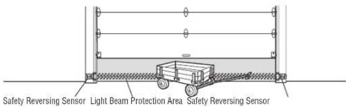
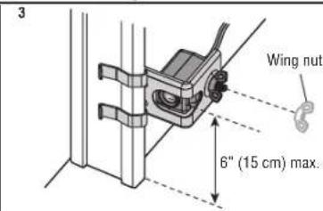
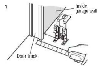
- Install the safety reversing sensor so beam is NO HIGHER than 6^ (15 cm) above garage floor.
IMPORTANT: The safety reversing sensors MUST be connected and aligned correctly before the garage door opener will move in the down direction.
The Protector System includes two safety reversing sensors which use a light beam to prevent the garage door from closing. The sending sensor (amber LED) transmits the beam to the receiving sensor (green LED) when both are powered and aligned. If an obstruction breaks the light beam while the door is closing, the door will stop, and reverse to the full open position.
When Installing the safety reversing sensors, check:
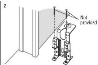
- Sensors are installed INSIDE the garage.
- Sensor lenses are facing each other.IMPORTANT: Do not allow direct sunlight to the receiving sensor (green LED).
- Sensor beam is NO HIGHER than 6'' (15 cm) above the floor and the light beam is unobstructed.
HARDWARE
Wing Nut (2)
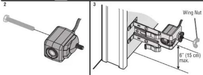
The safety reversing sensors are designed to clip onto the door track with the provided sensor brackets. If the door track will not support the sensor bracket a wall installation is recommended. The sensor beam should be NO HIGHER than 6^ (15 cm) above the floor.
DOOR TRACK INSTALLATION
- Slide the curved arms of the sensor bracket around the edge of the door track. Snap into place so that the sensor bracket is flush against the track.
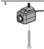
- Slide the hex screw through the sensor.
- Attach the sensor to the bracket with the wing nut. Make sure the lens is not obstructed by the bracket.
Repeat thesteps with theother sensor on theopposedoor track. Both lenses must faceeach other.

Installation
STEP 13 Install the Protector System (continued)
WALL OPTION
Make sure the brackets on each side are clear of the door track and have the same amount of clearance so the sensors will align correctly. If additional clearance is needed, use extension brackets 041A5281-1 (not provided) or wood blocks.
- Attach the sensor bracket against the wall with two lag screws (not provided).
- Slide the hex screw through the sensor.
- Attach the sensor to the bracket with the wing nut. Make sure the lens is not obstructed by the bracket.
Repeat the steps with the other sensor on the opposite side of the garage door. Both lenses must face each other.
FLOOR OPTION
- Measure the position of both sensor brackets so they will be the same distance from the wall and nobstructed.
- Attach the bracket to the floor with concrete anchors (not provided).
- Slide the hex screw through the sensor.
- Attach the sensor to the bracket with the wing nut. Make sure the lens is not obstructed by the bracket.
Repeat the steps with the other sensor on the opposite side of the garage door. Both lenses must face each other.
Installation
STEP 14 Wire the Safety Reversing Sensors
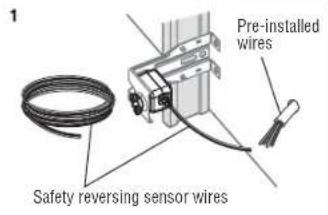
If your garage has pre-installed wiring for the safety reversing sensors, see OPTION B - PRE-WIRED INSTALLATION page 29.
OPTION A - INSTALLATION WITH NO PRE-WIRING
- Run the wire from both sensors to the garage door opener. Attach with staples, but DO NOT puncture the wire.
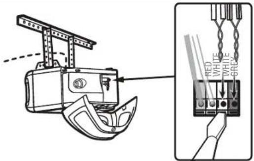
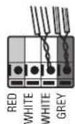
- Separate the sensor wires and strip insulation from each end. Twist the two white wires together. Then twist the two white/black wires together.
- Using a screwdriver, push in the terminal tabs, and insert the white wires into the white terminal. Insert the white/black wires into the grey terminal.
HARDWARE
Insulated Staple (Not Shown)
1
3
Installation
STEP 14 Wire the Safety Reversing Sensors (continued) OPTION A - PRE-WIRED INSTALLATION
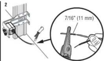
- Cut the sensor wires, making sure there is enough wire to reach the pre-installed wires from the wall.
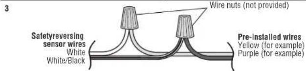
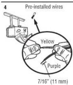
- Separate the sensor wires and strip insulation from each end. Choose two of the pre-installed wires and strip insulation from each end. Choose the same color pre-installed wires for each sensor.
- Connect the pre-installed wires to the sensor wires with wire nuts making sure the colors correspond for each sensor.
- At the garage door opener, strip the end of the wires previously connected to the sensors. Twist the like-colored wires together.
- Using a screwdriver, push in the terminal tabs, and insert the wire color connected to the sensor's white wire into the white terminal. Insert the other wire color connected to the sensor's white/black wire into the gray terminal.

Installation
STEP 15 Connect Power

WARNING
To prevent possible SERIOUS INJURY or DEATH from electrocution or fire:
- Be sure power is NOT connected to the opener, and disconnect power to circuit BEFORE removing cover to establish permanent wiring connection.
- Garage door installation and wiring MUST be in compliance with ALL local electrical and building codes.
- NEVER use an extension cord, 2-wire adapter, or change plug in ANY way to make it fit outlet. Be sure the opener is grounded.
To avoid installation difficulties, do not run the opener at this time.
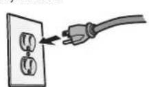
To reduce the risk of electric shock, your garage door opener has a grounding type plug with a third grounding pin. This plug will only fit into a grounding type outlet. If the plug doesn't fit into the outlet you have, contact a qualified electrician to install the proper outlet.
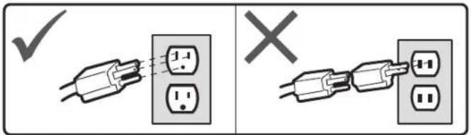
THERE ARE TWO OPTIONS FOR CONNECTING POWER:
OPTION A-TYPICAL WIRING
- Plug in the garage door opener into a grounded outlet.
- DO NOT run garage door opener at this time.
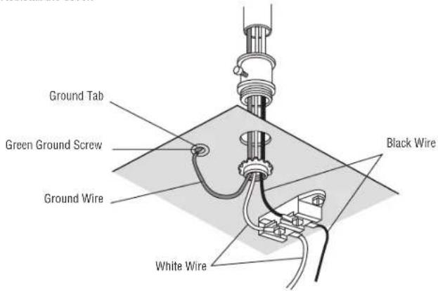
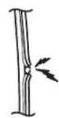
OPTION B - PERMANENT WIRING
If permanent wiring is required by your local code, refer to the following procedure. To make a permanent connection through the 7/8-inch hole in the top of the motor unit (according to local code):
- Remove the motor unit cover screws and set the cover aside.
- Remove the attached 3-prong cord.
- Connect the black (line) wire to the screw on the brass terminal; the white (neutral) wire to the screw on the silver terminal; and the ground wire to the green ground screw. The opener must be grounded.
- Reinstall the cover.
Installation
STEP 16 Align the Safety Reversing Sensors
IMPORTANT: The safety reversing sensors MUST be connected and aligned correctly before the garage door opener will move in the down direction.
When the garage door opener has power, check the safety reversing sensors. If the sensors are aligned and wired correctly, both LEDs will glow steadily.
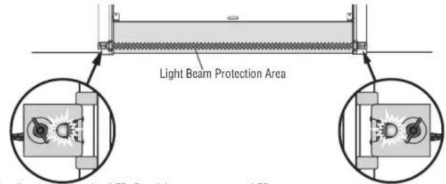
Sending sensor - amber LED Receiving sensor - green LED
The receiving sensor will have a sticker on the back.
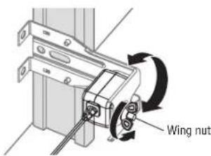
To align the safety reversing sensors:
- Loosen the wing nuts.
- Adjust the sensors up or down until both LEDs glow steady indicating alignment.
- Tighten the wing nut to secure the sensor.
SAFETY SENSOR TROUBLESHOOTING
If either of the sensor LEDs are off, there is no power to the sensor:
- Check that you have power to the garage door opener.
- Check the sensor wire is not shorted or broken.
- Check that the sensors are wired correctly; white wires to white terminal and white/black wires to grey terminal.
2
3
If the green receiving sensor LED is blinking, the sensors are obstructed or misaligned:
- Check for obstructions in the sensor light beam.
- Align the sensors.
- If the receiving sensor (green LED) faces direct sunlight, switch the receiving sensor with the sending sensor and repeat STEP 12 Install the Protector System page 27 to assure proper operation.
STEP 17 Ensure the Door Control is Wired Correctly
If the door control has been installed and wired correctly, the command LED on the control panel will blink or the LED behind the push button will blink if installed correctly.
Adjustments
Introduction
WARNING
Without a properly installed safety reversal system, persons (particularly small children) could be SERIOUSLY INJURED or KILLED by a closing garage door.
Incorrect adjustment of garage door travel limits will interfere with proper operation of safety reversal system.
After ANY adjustments are made, the safety reversal system MUST be tested. Door MUST reverse on contact with 1 - 1 / 2^n (3.8cm) high object (or 2x4 laid flat) on floor.
CAUTION
To prevent damage to vehicles, be sure fully open door provides adequate clearance.
Your garage door opener is designed with electronic controls to make setup and adjustments easy.
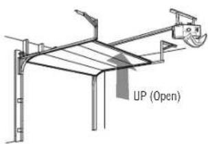
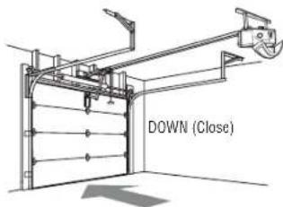
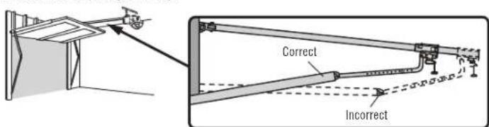
ONE-PIECE DOORS ONLY
When setting the UP travel for a one-piece door ensure that the door does not slant backwards when fully open (UP). If the door is slanted backwards this will cause unnecessary bucking and/or jerking when the door is opening or closing.
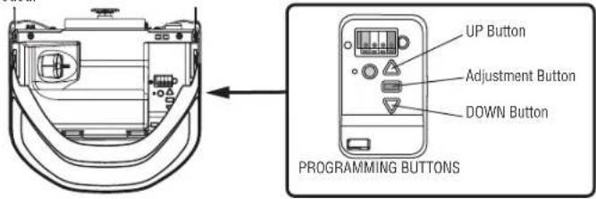
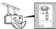
PROGRAMMING BUTTONS
The programming buttons are located on the left side panel of the garage door opener and are used to program the travel. While programming, the UP and DOWN buttons can be used to move the door as needed.
Adjustments
1 Program the Travel
WARNING
Without a properly installed safety reversal system, persons (particularly small children) could be SERIOUSLY INJURED or KILLED by a closing garage door.
- Incorrect adjustment of garage door travel limits will interfere with proper operation of safety reversal system.
- After ANY adjustments are made, the safety reversal system MUST be tested. Door MUST reverse on contact with 1 - 1 / 2^* (3.8 cm) high object (or 2x4 laid flat) on floor.
Note: While programming, the UP and DOWN buttons can be used to move the door as needed.
1 Press and hold the Adjustment Button until the UP Button begins to flash and/or a beep is heard. The Safety Reversing Sensors will be disconnected during the Program the Travel process.
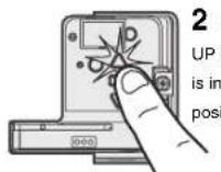
2 Press and hold the UP Button until the door is in the desired UP position.
3 Once the door is in the desired UP position press and release the Adjustment Button. The garage door opener lights will flash twice and the DOWN Button will begin to flash.
4 Press and hold the DOWN Button until the door is in the desired DOWN position.
5 Once the door is in the desired DOWN position press and release the Adjustment Button. The garage door opener lights will flash twice. Program the Travel is now complete. If the garage door opener lights flash 5 times, then programming has timed out and the Travel Limits have not been set. Please restart the Program the Travel process.
2 Automatic Force Set Up
Once both the up and down positions have been manually set, the Safety Reversing Sensors will reconnect and become operational. Then, the opener will enter a force-sensing operation by automatically moving the door to open and close. The garage door opener will sound an audible and visual alert before automatically oeping and closing the door. The garage door opener will beep three times, confirming that the Automatic Force Setup completed successfully. Adjustment is complete.
If you hear one long beep after the door attempts to move, then the Automatic Force Set Up has not completed successfully. Please start over at step 1 of Program the Travel.
Adjustments
3 Test the Safety Reversal System 4 Test the Protector System
WARNING WARNING
Without a properly installed safety reversal system, persons (particularly small children) could be SERIOUSLY INJURED or KILLED by a closing garage door.
Safety reversal system MUST be tested every month.
After ANY adjustments are made, the safety reversal system MUST be tested. Door MUST reverse on contact with 1 - 1 / 2^n (3.8cm) high object (or 2x4 laid flat) on the floor.
1 With the door fully open, place a 1-1/2 inch (3.8 cm) board (or a 2x4 laid flat) on the floor, centered under the garage door.
2 With the door fully open, place a 1-1/2 inch (3.8 cm) board (or a 2x4 laid flat) on the floor, centered under the garage door.
If the door stops but does not reverse:
- Repeat Program the Travel (see Adjustment Step 1);
- Repeat the Safety Reversal test.
If the test continues to fail, call a trained door systems technician.

Without a properly installed safety reversing sensor, persons (particularly small children) could be SERIOUSLY INJURED or KILLED by a closing garage door.
1 Open the door. Place an obstruction in the path of the door.
2 Press the remote control push button to close the door. The door will not move more than an inch (2.5 cm).
The garage door opener will not close from a remote control if the LED in either safety reversing sensor is off (alerting you to the fact that the sensor is misaligned or obstructed).
If the garage door opener closes the door when the safety reversing sensor is obstructed (and the sensors are no more than 6 inches [15 cm] above the floor), call for a trained door systems technician.
myQ® App Control
Connect With Your Smartphone
YOU WILL NEED:
Wi-Fi enabled smartphone, tablet or laptop
- Broadband Internet connection
Wi-Fi signal in the garage (2.4 GHz, 802.11b/g/n required), see page 5
- Password for your home network (router's main account, not guest network)
myQ serial number located on the garage door opener
DOWNLOAD THE myQ® APP TO SET UP AN ACCOUNT AND CONNECT
Open and close your door, get alerts and set schedules from anywhere. Connected smart garage door
openers also receive software updates to ensure the opener has the latest operational features
The garage door opener must run through a complete cycle before it will activate Wi-Fi® programming.
- Download the myQ App.
- Set up an account and connect.
If you already have the myQ App installed:
- Check that your mobile device has the latest software.
- Download the latest version of the myQ® App.


Download on the App Store
For more information on connecting your garage door opener, visit support.chamberlaingroup.com.
NOTES:
To erase the Wi-Fi settings from the opener, see page 39.
Google Play and the Google Play logo are trademarks of Google LLC.
App Store and the Apple and App Store logos are trademarks of Apple Inc.
| Wi-Fi Status | |
| LED | Definition |
| Blue | Off - Wi-Fi* is not turned on. Blinking - Garage door opener is in Wi-Fi*learn mode. Solid - Mobile device connected to the garage door opener. |
| Blue and Green | Blinking - Attempting to connect to router. |
| Green | Blinking - Attempting to connect to the Internet server. Solid - Wi-Fi* has been set up and garage door opener is connected to the Internet. |
Operation
IMPORTANT SAFETY INSTRUCTIONS
WARNING
To reduce the risk of SEVERE INJURY or DEATH:
- READ AND FOLLOW ALL WARNINGS AND INSTRUCTIONS.
- ALWAYS keep remote controls out of reach of children. NEVER permit children to operate or play with garage door control push buttons or remote controls.
- ONLY activate garage door when it can be seen clearly, it is properly adjusted, and there are no obstructions to door travel.
- ALWAYS keep garage door in sight and away from people and objects until completely closed. NO ONE SHOULD CROSS THE PATH OF THE MOVING DOOR.
- NO ONE SHOULD GO UNDER A STOPPED, PARTIALLY OPENED DOOR.
- If possible, use emergency release handle to disengage trolley ONLY when garage door is CLOSED. Use caution when using this release with the door open. Weak or broken springs or unbalanced door could result in an open door falling rapidly and/or unexpectedly and increasing the risk of SEVERE INJURY or DEATH.
- NEVER use emergency release handle unless garage doorway is clear of persons and obstructions.
-
NEVER use handle to pull garage door open or closed. If rope knot becomes untied, you could fall.
-
After ANY adjustments are made, the safety reversal system MUST be tested.
- Safety reversal system MUST be tested every month. Garage door MUST reverse on contact with 1 - 1 / 2^ (3.8 cm) high object (or a 2x4 laid flat) on the floor. Failure to adjust the garage door opener properly increases the risk of SEVERE INJURY or DEATH.
- ALWAYS KEEP GARAGE DOOR PROPERLY BALANCED (see page 3). An improperly balanced door may NOT reverse when required and could result in SEVERE INJURY OR DEATH.
- ALL repairs to cables, spring assemblies and other hardware, ALL of which are under EXTREME tension, MUST be made by a trained door systems technician.
- ALWAYS disconnect electric power to garage door opener BEFORE making ANY repairs or removing covers.
- This operator system is equipped with an unattended operation feature. The door could move unexpectedly. NO ONE SHOULD CROSS THE PATH OF THE MOVING DOOR.
- DO NOT install on a one-piece door if using devices or features providing unattended close. Unattended devices and features are to be used ONLY with sectional doors.
16. SAVE THESE INSTRUCTIONS.
Using your Garage Door Opener
The garage door opener can be activated through a wall-mounted door control, remote control, wireless keyless entry or myQ App.
When the door is closed and the garage door opener is activated the door will open. If the door makes contact with an obstruction while opening, the door will stop, opener beeps and lights flash 5 times. When the door is in any position other than closed and the garage door opener is activated, the door will close. If the garage door makes contact with an obstruction while closing, the door will reverse, opener beeps and lights flash 5 times. However, you can close the door if you hold the button on the door control or keyless entry until the door is fully closed.
The safety reversing sensors do not affect the opening cycle. The safety reversing sensor must be connected and aligned correctly before the garage door opener will move in the down direction.
The garage door opener lights will turn on when the opener is initially plugged in, the opener is activated, or power is restored after interruption. The garage door opener lights automatically turn off after a set length of time. To adjust the light settings, see Using Your Door Control.
Operation
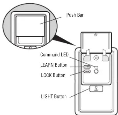
MULTI-FUNCTION CONTROL PANEL
SYNCHRONIZE THE DOOR CONTROL: To synchronize the door control to the garage door opener, press the push bar until the garage door opener activates (it may take up to 3 presses). Test the door control by pressing the push bar; each press of the push bar will activate the garage door opener. PUSH BAR: Press the push bar to open or close the door. LEARN BUTTON: Use to program compatible remote controls, wireless keyless entries and myQ° devices to the garage door opener.
LOCK: Prevents remote controls from working, while still allowing activation from the door control and keyless entry. (Factory setting is OFF.)
Turn ON.
Press and hold the LOCK button for 2 seconds. The command LED will flash as long as the lock feature is on.
Turn OFF:
Press and hold the LOCK button for 2 seconds. The command LED will stop flashing and normal operation will resume.
LIGHT BUTTON: Turns the garage door opener lights on or off when pressed. Lights stay on for 4-1/2 minutes (factory setting). The LIGHT button will not control the lights when the door is in motion.
To change the amount of time the lights stay on: Press and hold the LOCK button (approximately 10 seconds) until the garage door opener lights flash. The time interval is indicated by the number of times the garage door opener lights flash:
1 flash is 1-1/2 minutes
2 flashes is 2-1/2 minutes
3 flashes is 3-1/2 minutes
4 flashes is 4-1/2 minutes
To cycle through the time intervals repeat the step above. If the push bar LED is continuously blinking, the LOCK feature needs to be turned off.
PUSH BUTTON DOOR CONTROLUsing yo
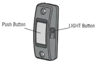
SYNCHRONIZE THE DOOR CONTROL: To synchronize the door control to the garage door opener, press the push button until the garage door opener activates (it may take up to 3 presses).
PUSH BUTTON: Press the LIGHT button to turn the garage door opener lights on or off. When the lights are turned on they will stay on until the LIGHT button is pressed again, or until the garage door opener is activated. Once the garage door opener is activated the lights will turn off after the specified period of time (the factory setting is 4-1/2 minutes). The LIGHT button will not control the lights when the door is in motion.
Operation
Remote Control and Keyless Entry
PRE-PROGRAMMED REMOTE CONTROL INCLUDED, NO NEED TO PROGRAM THE REMOTE.
To add or reprogram a remote control, follow the instructions below. Older Chamberlain remote controls are NOT compatible.
PROGRAM USING THE MULTI-FUNCTION CONTROL PANEL
- Press the LEARN button on the door control to enter programming mode. The command LED will flash once.
- Press the LEARN button again, the command LED will flash once again.
- Remote Control: Press the button on the remote control that you wish to operate your garage door. Keyless Entry: Enter a 4-digit personal identification number (PIN) of your choice on the keyless entry keypad. Then press the ENTER button.
PROGRAM USING THE PUSH BUTTON DOOR CONTROL
- Press and hold the light button and the push button until the push button LED begins to blink.
- Remote control: Press the button on the remote control that you wish to operate your garage door.
Keyless entry: Enter a 4-digit personal identification number (PIN) of your choice on the keyless entry keypad. Then press the ENTER button.
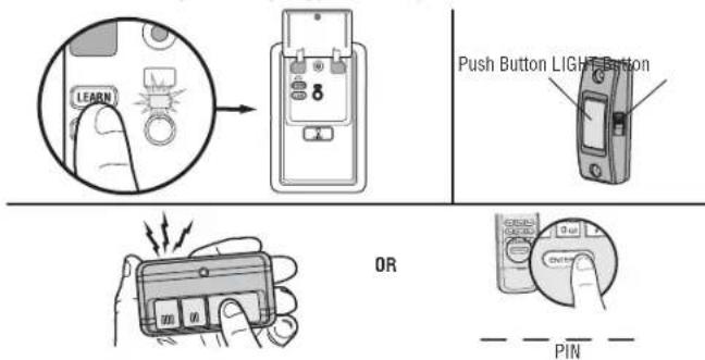
The garage door opener lights will flash (or two clicks will be heard) when the code has been programmed. Repeat the steps for programming additional remote controls or keyless entry devices. If programming is unsuccessful, follow the steps to program using the garage door opener LEARN button.
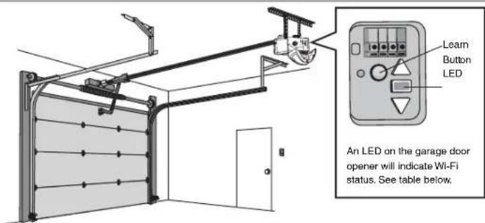
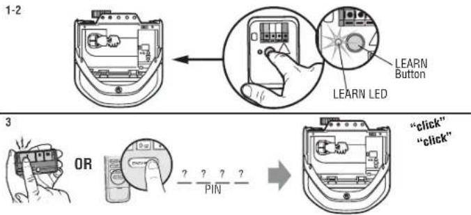
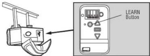
PROGRAM USING THE GARAGE DOOR OPENER LEARN BUTTON
- Locate the LEARN Button
- Press and immediately release the LEARN button. The LEARN LED will glow steady for 30 seconds. Within 30 seconds...
- Remote Control: Press and hold the button on the remote control that you wish to use. Keyless Entry: Enter a 4-digit personal identification number (PIN) of your choice on the keyless entry keypad. Then press and hold the ENTER button.
Releasethebutton when thegaragedoor opener lights blinkor twoclicks areheard.
HomeLink
If your vehicle is equipped with HomeLink, a Compatibility Bridge™ (not included) may be necessary for certain vehicles. Visit bridge.chamberlain.com to find out if a Bridge is needed.
Operation
Erase the Memory
ERASE ALL REMOTE CONTROLS AND KEYLESS ENTRIES
- Press and hold the LEARN button on garage door opener until the learn LED goes out (approximately 6 seconds). All remote control and keyless entry codes are now erased. Reprogram any accessory you wish to use.
ERASE ALL DEVICES INCLUDING myQ® ENABLED ACCESSORIES
- Press and hold the LEARN button on garage door opener until the learn LED goes out (approximately 6 seconds).
- Immediately press and hold the LEARN button again until the leam LED goes out. All codes are now erased. Reprogram any accessory you wish to use.
ERASE THE CONNECTION FROM GARAGE DOOR OPENER TO HOME WI-FT NETWORK
- Press and hold the black adjustment button on the garage door opener until 3 beeps are heard (Approximately 6 seconds).
To Open the Door Manually
WARNING
To prevent possible SERIOUS INJURY or DEATH from a falling garage door:
If possible, use emergency release handle to disengage trolley ONLY when garage door is CLOSED. Weak or broken springs or unbalanced door could result in an open door falling rapidly and/or unexpectedly.
- NEVER use emergency release handle unless garage doorway is clear of persons and obstructions.
NEVER use handle to pull door open or closed. If rope knot becomes untied, you could fall.
- The door should be fully closed if possible.
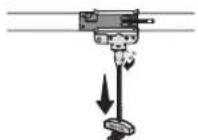
- Pull down on the emergency release handle so the trolley release arm snaps to the vertical position. The door can now be raised and lowered as often as necessary.
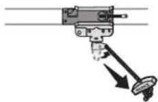
- Pull the emergency release handle toward the garage door opener so the trolley release arm snaps to the horizontal position. The trolley will reconnect on the next UP or DOWN operation, either manually or by using the door control or remote control.
Maintenance
Maintenance Schedule
EVERY MONTH
- Manually operate door. If it is unbalanced or binding, call a trained door systems technician.
- Check to be sure door opens and closes fully. Adjust if necessary, see pape 33.
Test the safety reversal system. Adjust if necessary, see page 35.
EVERY YEAR
- Oil door rollers, bearings and hinges. The garage door opener does not require additional lubrication. Do not grease the door tracks.
- Test the battery backup and consider replacing the battery to ensure the garage door opener will operate during an electrical power outage, see page 36 to test the battery backup.
The Remote Control Battery
WARNING
To prevent possible SERIOUS INJURY or DEATH:
NEVER allow small children near batteries.
If battery is swallowed, immediately notify doctor.
To reduce risk of fire, explosion or chemical burn:
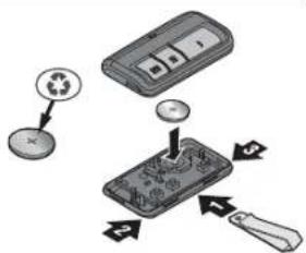
- Replace ONLY with 3V CR2032 coin batteries.
DO NOT recharge, disassemble, heat above 212^ (100^) or incinerate.
The 3V CR2032 Lithium battery should produce power for up to 3 years. If the battery is low, the remote control's LED will not flash when the button is pressed.
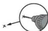
To replace battery, pry open the case first in the middle (1), then at each side (2 and 3) with the visor clip. Replace the batteries with only 3V CR2032 coin cell batteries. Insert battery positive side up. Dispose of old batteries properly.
NOTICE: This device complies with part 15 of the FCC rules and Innovation, Science and Economic Development Canada license-exempt RSSs. Operation is subject to the following two conditions: (1) this device may not cause harmful interference, and (2) this device must accept any interference received, including interference that may cause undesired operation.
Any changes or modifications not expressly approved by the party responsible for compliance could void the user's authority to operate the equipment.
This device must be installed to ensure a minimum 20~cm (8 in.) distance is maintained between users/ bystanders and device.
This device has been tested and found to comply with the limits for a Class B digital device, pursuant to part 15 of the FCC rules and Industry Canada ICES standard. Those limits are designed to provide reasonable protection against harmful interference in a residential installation. This equipment generates, uses and can radiate radio frequency energy and, if not installed and used in accordance with the instructions, may cause harmful interference to radio communications. However, there is no guarantee that interference will not occur in a particular installation. If this equipment does cause harmful interference to radio or television reception, which can be determined by turning the equipment off and on, the user is encouraged to try to correct the interference by one or more of the following measures:
Reorient or relocate the receiving antenna.
- Increase the separation between the equipment and receiver.
- Connect the equipment into an outlet on a circuit different from that to which the receiver is connected.
- Consult the dealer or an experienced radio/TV technician for help.
Troubleshooting
Diagnostic Chart
Your garde door opener is programmed with self-diagnostic capabilitie.The UP and DOWN arrows on the garce door opener flash the diagnostic codes.
DIAGNOSTICCODE SYMPTOM SOLUTION
| 1 1 The garage door opener will not close. | Safety reversing sensors are not installed, connected, or wires may be cut. Inspect sensor wires for a disconnected or cut wire. |
| 1 2 The garage door opener will not close. | There is a short or reversed wire for the safety reversing sensors. Inspect safety sensor wire at all staple and connection points, replace wire or correct as needed. |
| 1 3 The door control will not function. | The wires for the door control are shorted or the door control is faulty. Inspect door control wires at all staple and connection points, replace wire or correct as needed. |
| 1 4 The garage door opener will not close. | Safety reversing sensors are misaligned or were momentarily obstructed. Realign both sensors until both LEDs are glowing steady. Make sure nothing is hanging or mounted on the door that would interrupt the sensor's path while closing. |
| 1 5 Door moves 6-8" (15-20 cm) stops or reverses. | Manually open and close the door. Check for binding or obstructions, such as a broken spring or door lock, correct as needed. Check wiring connections at travel module and at the logic board. Replace travel module if necessary. |
| No movement, only a single click. | |
| Manually open and close the door. Check for binding or obstructions, such as a broken spring or door lock, correct as needed. Replace logic board if necessary. | |
| Openers hums for 1-2 seconds no movement. | |
| 1 6 Door coasts after it has come to a complete stop. | Manually open and close the door. Check for binding or obstructions, such as a broken spring or door lock, correct as needed. Replace motor if necessary. |
| 2 1-5 No movement, or sound. Replace logic board. | |
| 3 2 Unable to set the travel or retain position. Check travel module for proper assembly, replace if necessary. | |
| 3 3 The battery status LED is constantly flashing green. Battery backup charging circuit error, replace the logic board. | |
| 4 14 Door is moving, stops or reverses. Opener beops and lights flash. | Manually open and close the door. Check for binding or obstructions, such as a broken spring or door lock, correct as needed. If the door is binding or sticking contact a trained door systems technician. If door is not binding or sticking attempt to reprogram travel, see Program the Travel page 31. |
| 4 5 Opener runs approximately 6-8" (15-20 cm), stops and reverses. | Communication error to travel module. Check travel module connections, replace travel module if necessary. |
| 4 6 The garage door opener will not close. | Safety reversing sensors are misaligned or were momentarily obstructed. Realign both sensors to ensure both LEDs are steady and not flickering. Make sure nothing is hanging or mounted on the door that would interrupt the sensor's path while closing. |
Troubleshooting
Additional Troubleshooting
My garage door opener beeps and flashes its lights before door closes:
- Garage door opener has been activated through a device or feature such as Timer-to-Close or garage door monitor.
My garage door opener stops, reverses, beeps and flashes its lights:
- Check for binding or obstructions anywhere along the track to garage floor.
My remote control will not activate the garage door:
- Verify the lock feature is not activated on the door control.
- Reprogram the remote control.
- If the remote control will still not activate the door check the diagnostic codes to ensure the garage door opener is working properly.
My door will not close
The safety reversing sensor must be connected and aligned correctly before the garage door opener will move in the down direction.
- Check for binding or obstructions anywhere along the track to garage floor.
- The safety reversing sensor must be connected and aligned correctly before the garage door opener will move in the down direction.
Verify the safety reversing sensors are properly installed, aligned and free of any obstructions.
If the receiving sensor (green LED) faces direct sunlight, switch the receiving sensor with the sending sensor so the receiving sensor is not in direct sunlight.
WI-Fl*troubleshooting
The garage door opener will NOT enter Wi-Fi learn mode:
After the initial installation of the garage door opener, the garage door opener must complete a full cycle (open and closed) before the Wi-Fi® learn mode can be activated.
- If there has been a recent power outage, the garage door opener must complete a full cycle before the Wi-Fi ^P learn mode can be activated.
See page 37 to activate Wi-Fi LEARN mode.
If your black adjustment button is not solid green go to support.chamberlaingroup.com.
My vehicle's Homelink is not programming to my garage door opener:
Compatibility Bridge (not included) may be necessary for certain vehicles. Visit bridge.chamberlain.com to find out if a Bridge is needed.
My neighbor's remote control opens my garage door:
Erase the memory from your garage door opener and reprogram the remote control(s).
Safety sensor LED lights are not lit:
If the sensor LEDs do not glow steadily when the opener is activated, see SAFETY SENSOR TROUBLESHOOTING page 32.
Warranty
Contact Information
STOP!
This garage door opener WILL NOT work until the safety reversing sensors are properly installed and aligned.
Visit us onlineat:
support.chamberlaingroup.com
CHAMBERLAIN®LIMITED WARRANTY
The Chamberlain Group, Inc.® ("Seller") warrants to the first retail purchaser of this product, for the residence in which this product is originally installed, that it is free from defects in materials and/or workmanship for a specific period of time as defined below (the "Warranty Period"). The warranty period commences from the date of purchase.
| WARRANTY PERIOD | |||
| Motor | Parts | Motor | Accessories |
| C2405C | 1 year | 10 years | 1 year |
| D2405C | 1 year | 6 years | 1 year |
| C2202C | 1 year | 6 years | 1 year |
| D2101C | 1 year | 6 years | 1 year |
| C2102C | 1 year | 6 years | 1 year |
The proper operation of this product is dependent on your compliance with the instructions regarding installation, operation, and maintenance and testing. Failure to comply strictly with those instructions will void this limited warranty in its entirety. If, during the limited warranty period, this product appears to contain a defect covered by this limited warranty, visit chamberlain.com, before dismantling this product. You will be advised of disassembly and shipping. Then send the product or component, pre-paid and insured, as directed to our service center for warranty repair. Please include a brief description of the problem and a dated proof-of-purchase receipt with any product returned for warranty repair. Products returned to Seller for warranty repair, which upon receipt by Seller are confirmed to be defective and covered by this limited warranty, will be repaired or replaced (at Seller's sole option) at no cost to you and returned pre-paid. Defective parts will be repaired or replaced with new or factory-rebuilt parts at Seller's sole option. [You are responsible for any costs incurred in removing and/or reinstalling the product or any component].
ALL IMPLIED WARRANTYES FOR THE PRODUCT, INCLUDING BUT NOT LIMITED TO ANY IMPLIED WARRANTYES OF MERCHANTABILITY AND FITNESS FOR A PARTICULAR PURPOSE, ARE LIMITED IN DURATION TO THE APPLICABLE LIMITED WARRANTY PERIOD SET FORTH ABOVE FOR THE RELATED COMPONENT(S), AND NO IMPLIED WARRANTYES WILL EXIST OR APPLY AFTER SUCH PERIOD. Some States and Provinces do not allow limitations on how long an implied warranty lasts, so the above limitation may not apply to you. THIS LIMITED WARRANTY DOES NOT COVER NON-DEFECT DAMAGE, DAMAGE CAUSED BY IMPROPER INSTALLATION, OPERATION OR CARE (INCLUDING, BUT NOT LIMITED TO ABUSE, MISUSE, FAILURE TO PROVIDE REASONABLE AND NECESSARY MAINTENANCE, UNAUTHORIZED REPAIRS OR ANY ALTERATIONS TO THIS PRODUCT), LABOR CHARGES FOR REINSTALLING A REPAIDRED OR REPLACED UNIT, REPLACEMENT OF CONSUMABLE ITEMS (E.G., BATTERIES IN REMOTE CONTROL TRANSMITTERS AND LIGHT BULBS), OR UNITS INSTALLED FOR NON-RESIDENTIAL USE. THIS LIMITED WARRANTY DOES NOT COVER ANY PROBLEMS WITH, OR RELATING TO, THE GARAGE DOOR OR GARAGE DOOR HARDWARE, INCLUDING BUT NOT LIMITED TO THE DOOR SPRINGS, DOOR ROLLERS, DOOR ALIGNMENT OR HINGES. THIS LIMITED WARRANTY ALSO DOES NOT COVER ANY PROBLEMS CAUSED BY INTERFERENCE. UNDER NO CIRCUMSTANCES SHALL SELLER BE LIABLE FOR CONSEQUENTIAL, INCIDENTAL OR SPECIAL DAMAGES ASING IN CONNECTION WITH USE, OR INABILITY TO USE, THIS PRODUCT. IN NO EVENT SHALL SELLER'S LIABILITY FOR BREACH OF WARRANTY, BREACH OF CONTRACT, NEGLIGENCE OR STRICT LIABILITY EXCEED THE COST OF THE PRODUCT COVERED HEREBY. NO PERSON IS AUTHORIZED TO ASSUME FOR US ANY OTHER LIABILITY IN CONNECTION WITH THE SALE OF THIS PRODUCT.
Some states and provinces do not allow the exclusion or limitation of consequential, incidental or special damages, so the above limitation or exclusion may not apply to you. This limited warranty gives you specific legal rights, and you may also have other rights, which vary from state to state and province to province.
Automatic Garage Door Opener Safety & Maintenance Guide
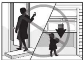
Garage Door Opener Safety – An Automatic Decision
garade door is the largest moving object in the home. An improperly adjusted garage door and opener can exer deadly force when the door closes - which could lead to entrapment of children or adults and subsequent injury or death.
Proper installation, operation, maintenance, and testing of the garage door and automatic opener are necessary to provide a safe, trouble-free system. Careless operation or allowing children to play with or use garage door opener controls are also dangerous situations that can lead to tragic results. A few simple precautions can protect your family and friends from potential harm.
Please review the safety and maintenance tips in this guide carefully and keep it for reference. Check the operation of your garage door and opener to ensure they function in a safe and trouble-free manner. Be sure to read all Important Safety Information found in your garage door opener's manual as it provides more details and safety considerations than can be supplied with this guide.
Garage Door Openers are Not Toys
Discuss garage door and opener safety with your children. Explain the danger of being trapped under the door.
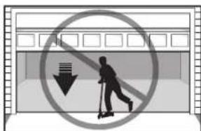
Stay away from a moving door.
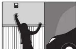
The wall-mounted push button should be out of reach of children, at least 5 feet from the nearest standing surface and away from all moving parts. Mount and use the button where you can clearly see the closing garage door.
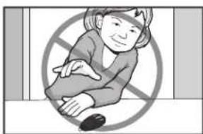
Keep transmitters and remote controls out of reach of children.
Do not let children play with or use transmitters or other remote control devices.
Keep the door in sight until it completely closes when using the wall-mounted push button or transmitter.
Routine Maintenance Can Prevent Tragedies
Make monthly inspection and testing of your garage door and opener system a part of your regular routine. Review your owner's manual for both the door and door opener. If you don't have the owner's manuals, contact the manufacturer(s) and request a copy for your specific model(s). Look for the opener model number on the back of the power unit.

WARNING - SPRINGS ARE UNDER HIGH TENSION. ONLY QUALIFIED INDIVIDUALS SHOULD ADJUST THEM.
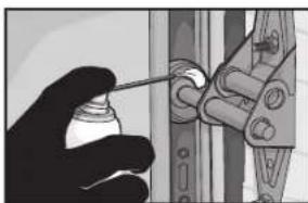
Visually check the door and installation:
Starting with the door in the closed position, use the manual disconnect on the opener to disconnect the door.
- Look for signs of wear or damage on hinges, rollers, springs, and door panels.
These parts may require periodic lubrication. Check the owner's manual for suggested maintenance.
If any signs of damage are evident, contact a trained door systems technician for assistance.
- Verify the photoeye height is no higher than 6'' from the garage floor.
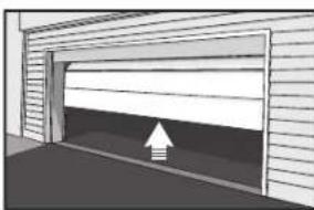
Test the door for proper operation:
- Open and close the door manually using handles or suitable gripping points.
The door should move freely and without difficulty.
The door should balance and stay partially open 3-4 feet above the floor.
If you detect any signs of improper operation, contact a trained door systems technician for assistance.
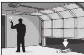
Test the opener safety features:
- Reconnect the opener to the door using the manual disconnect and open the door.
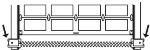
Place a 2x4 board flat in the path of the door (1) and try to close it (2). The door should stop when it comes
in contact with the 2x4 and then reverse direction.
Block the photoelectric sensor by waving an object in front of the sensor and attempt to close the door. The
door should not close unless the wall-mounted push button is manually held during operation
If the opener does not perform as described, contact a trained door systems technician for assistance.

DASMA.
Door & Access Systems International Association International
Repair Parts
Rail Assembly Parts Installation Parts
| Description Part Number |
| 1 Chain and cable 041A5807 |
| 2 Pulley K144C0056 |
| 3 Master link 004A1008 |
| 4 Rail 041A5665 |
| 5 Trolley assembly: clevis pin (1) and ring (1) 041C5141-1 |
| 6 "U" bracket 041D0598-1 |
| Not shown |
| Wear pads 041A7276 |
| Hardwarebag 041A7920-1 |
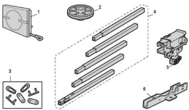
| Description Part Number | |
| 1 Curved door arm 041B0035B | |
| 2 Door bracket with clevis pin and fastener 041A5047 | |
| 3 Emergency release rope and handle | 041A2828 |
| 4 Header bracket with clevis pin and fastener | 041A5047-2 |
| 5 Remote control visor clip | K029B0137 |
| 6 Safety sensor bracket | 041-0155-000 |
| 7 Safety sensor kit: receiving and sending sensors with 2-conductor wire | 041-0136-000 |
| 8 Straight door arm | 4178B0034B |
| 9 White and red/white wire | 041B4494-1 |
| 10 3V CR2032 lithium battery | K010A0020 |
| 11 Hanging brackets | 012B0776 |
| Not shown | |
| Installation Manual | 114-5554-000 |

Repair Parts

Garage Door Opener Parts - C2102C
| Description Part Number | |
| 1 Chain spreader 041A5615 | |
| 2 Gear and sprocket 041C4220A | |
| 3 End panel with light socket 041A7760 | |
| 4 Light socket 041C0279 | |
| 5 Light lens 041-0144 | |
| 6 Capacitor 030B0532-1 | |
| 7 Capacitor bracket K012A0373 | |
| 8 Travel module 041D7742-7 | |
| 9 Cover 041-0228-000 | |
| 10 Receiver logic board 045ACT | |
| 11 Logic board end panel 041DB374 | |
| 12 Motor with travel module 041D7440 | |
| 13 Line cord 041B4245-1 | |
| 14 Terminal block 041A3150 | |
| Not shown | |
| Wire harness 041A7945 |
Repair Parts

Garage Door Opener Parts C2405C and D2405C
Description Part Number
1 Chain spreader 041A5615
2 Gear and sprocket 041C4220A
3 End panel with light socket 041-0037-000
4 Light socket 041C0279
5 Light lens 041-0144
6 Capacitor 030B0532-1
7 Capacitor bracket K012A0373
8 Travel module 041D7742-7
9 Cover 041-0028-000
10 Logic Board 050ACTWF
11 End panel for receiver logic board 041-0025-000
12 Motor with travel module 041D7440
13Line cord 041B4245-1
14 Terminal block 041A3150
Not shown
Wire harness 041A7946
Repair Parts

Garage Door Opener Parts - Model C2202C
Description Part Number
| 1 Chain spreader 041A5615 | |
| 2 Gear and sprocket 041C4220A | |
| 3 End panel with light socket 041-0037-000 | |
| 4 Light socket 041C0279 | |
| 5 Light lens 041-0144 | |
| 6 Capacitor 030B0532-1 | |
| 7 Capacitor bracket K012A0373 | |
| 8 Travel module 041D7742-7 | |
| 9 Cover 041-0028-000 | |
| 10 Logic Board 050ACTWF | |
| 11 End panel for receiver logic board | 041-0025-000 |
| 12 Motor with travel module | 041D7440 |
| 13 Line cord | 041B4245-1 |
| 14 Terminal block | 041A3150 |
| Not shown | |
| Wire harness | 041A7946 |
Repair Parts
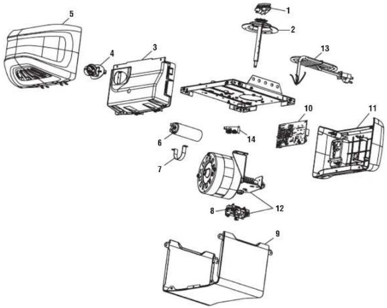
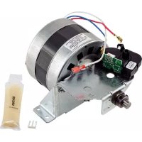
Garage Door Opener Parts - Model D2101C
| Description Part Number | |
| 1 Chain spreader 041A5615 | |
| 2 Gear and sprocket 041C4220A | |
| 3 End panel with light socket 041D8129 | |
| 4 Light socket 041C0279 | |
| 5 Light lens 041-0144 | |
| 6 Capacitor 030B0532-1 | |
| 7 Capacitor bracket K012A0373 | |
| 8 Travel module 041D7742-7 | |
| 9 Cover 041-0228-000 | |
| 10 Logic Board 045ACT | |
| 11 End panel for receiver logic board 041D8374 | |
| 12 Motor with travel module 041D7440 | |
| 13 Line cord 041B4245-1 | |
| 14 Terminal block 041A3150 | |
| Not shown | |
| Wire harness 041A7945 |
© 2021, The Chamberlain Group, Inc.
All Rights Reserved
Wi-Fi is a registered trademark of Wi-Fi Alliance
HomeLink is a registered trademark of Gentex Corporation
The Chamberlain Group, Inc.
300Windsor Drive
Oak Brook, IL 60523
CHAMBERLAIN
www.chamberlain.com
support.chamberlaingroup.com
GARANTIE LIMITEE CHAMBERLAIN
© 2021, The Chamberlain Group, Inc.
The Chamberlain Group, Inc.
300 Windsor Drive
Oak Brook, IL 60523