ZIBRM420 - Lawn mower Zipper - Free user manual and instructions
Find the device manual for free ZIBRM420 Zipper in PDF.

| Product type | Gasoline lawn mower |
| Brand | Zipper |
| Model | ZIBRM420 |
| Engine | 1 cylinder 4-stroke, 79.8 cm³, 1.2 kW at 3000 rpm |
| Fuel | Unleaded gasoline RON 95 |
| Fuel tank capacity | 0.8 L |
| Engine oil | 15W40, volume 0.45 L |
| Cutting width | 420 mm |
| Cutting height | 25-75 mm (6 adjustable positions) |
| Grass catcher volume | 45 L |
| Starting system | Starter cord (recoil) with primer bulb |
| Net weight | 25.5 kg |
| Gross weight | 28.5 kg |
| Packaging dimensions (L×W×H) | 720 × 520 × 440 mm |
| Guaranteed sound power level LWA | 96 dB(A) |
| Maximum permissible incline | 20° |
| Spark plug | F7RTC (gap 0.7-0.8 mm) |
| Air filter | Foam element, washable |
| Cutting functions | Bagging, rear discharge, mulching (mulch plug included) |
| Blade brake | Yes, brake bar |
| Adjustable handle | Yes, adjustable height (positions H and L) |
| Warranty | 2 years (non-commercial use), 1 year (commercial use) |
Frequently Asked Questions - ZIBRM420 Zipper
User questions about ZIBRM420 Zipper
0 question about this device. Answer the ones you know or ask your own.
Ask a new question about this device
Download the instructions for your Lawn mower in PDF format for free! Find your manual ZIBRM420 - Zipper and take your electronic device back in hand. On this page are published all the documents necessary for the use of your device. ZIBRM420 by Zipper.
USER MANUAL ZIBRM420 Zipper
natural_image
Green and black lawn mower with blue wheels and a black handle (no text or symbols visible)ZI-BRM420
EAN: 9120039233833

natural_image
Green and black lawn mower with blue blades and black handle (no visible text or symbols)ZI-BRM508
EAN: 9120039233840
CE
ATTENTION: Check Oil! Engine don't start with low oil!!

1 INHALT/ INDEX
1 INHALT/ INDEX 2
14.1 Intended use of the machine....27
14.1.1 Technical Restrictions 27
14.1.2 Prohibited Use / Forseeable Misuse 27
14.2 User Qualification 27
14.3 Safety instructions 27
14.4 Special safety instructions for the operation 28
14.5 Safety instructions for machines with combustion engine....28
14.6 Hazard warnings 28
15 ASSEMBLY 29
15.1 Checking Delivery Content....29
15.2 Assembling the Machine.... 29
15.3 Checklist before Start-up....31
15.3.1 Checking/refilling engine oil 32
15.3.2 Checking fuel tank level / Refuelling Fuel Tank 32
16 OPERATION 33
16.1 Informationen on Initial Start-up 33
16.1.1 Test Run Initial Start-up.... 33
16.1.2 Notes for the first 20 operating hours 33
16.2 Operating instructions....33
16.3 Starting the Machine .... 34
16.4 Stopping the machine....35
17 MAINTENANCE 36
17.1 Maintenance and Servicing Plan 36
17.2 Changing the Engine Oil .... 36
17.3 Checking / Replacing blades ...... 37
17.3.1 Checking the blade 37
17.3.2 Replacing the blade 37
17.4 Replacing and Cleaning the Grass Bag....38
17.4.1 Cleaning 38
17.4.2 Replacing 38
17.5 Adjusting the clutch and brake cables 38
17.5.1 Adjusting the clutch cable 38
17.5.2 Brake cable adjustment 39
17.6 Cleaning the air filter....39
17.7 Cleaning / Replacing the Spark Plug .... 39
18 TRANSPORT 40
19 STORGAE 40
20 DISPOSAL 41
21 TROUBLESHOOTING 41
22 AVANT-PROPOS (FR) 42
23 SECURITE 43
EN CE-Conformal! - This product complies with the EC-directives.
EN Follow the instructions!
FR Respecter le manuel !


EN No open flame, fire, open source of ignition and smoking prohibited!
EN Danger of Intoxication! Only use outdoors and far from open windows and vents!
EN Wear personal protective equipment!
EN Keep safe distance!
EN Remove spark plug connector before maintenance work
EN Parts thrown away
EN Blades in movement. Do not put hands or feet near or under the opening of the cutting plate.
EN ATTENTION: Check Oil! Engine don't start with low oil!!
text_image
Technical diagram of a mechanical assembly with labeled parts and cross-sectional views1. Montage Griff
natural_image
Technical diagram of a mechanical component with directional arrows indicating movement or force (no text or symbols)text_image
Diagram showing two labeled mechanical or physical components with arrows indicating motion or force directionThis manual contains information and important instructions for the installation and correct use of the ZIPPER gasoline lawn mower ZI-BRM420 and ZI-BRM508.
Following the usual commercial name of the machine (see cover) is substituted in this manual with the name "machine".

This manual is part of the product and shall not be stored separately from the product. Save it for later reference and if you let other people use the product, add this instruction manual to the product.
Please read and obey the security instructions!
Due to constant advancements in product design, construction pictures and content may diverse slightly. However, if you discover any errors, inform us please.
Technical specifications are subject to changes!
Please check the product contents immediately after receipt for any eventual transport damage or missing parts.
Claims from transport damage or missing parts must be placed immediately after initial product receipt and unpacking before putting the product into operation.
Please understand that later claims cannot be accepted anymore.
Copyright
© 2018
This document is protected by international copyright law. Any unauthorized duplication, translation or use of pictures, illustrations or text of this manual will be pursued by law. Court of jurisdiction is the regional court Linz or the competent court for 4707 Schlüsslberg, Austria!
Customer service contact
This section contains information and important notices for safe commissioning and handling of machine.

For your own safety, read these operating instructions carefully before putting the machine into operation. This will enable you to handle the machine safely and prevent misunderstandings as well as possible damage to property and persons. Also observe the symbols and pictograms used as well as the safety instructions and hazard warnings!
14.1 Intended use of the machine
The machine is intended exclusively for the following activities:
For mowing and mulching lawns within the specified application limits.
ZIPPER-MASCHINEN assumes no responsibility or warranty for any other use or use beyond this and for any resulting damage to property or injury.
14.1.1 Technical Restrictions
The machine is intended for use under the following ambient conditions:
Relative humidity: max. 65 %
Temperature (for operation) +5°C bis +40°C
Temperature (for storage and/or transport) -20^ C bis +55^ C
14.1.2 Prohibited Use / Forseeable Misuse
• Operation of the machine without adequate physical and mental aptitude
- Operating the machine without appropriate knowledge of the operating instructions (machine + motor).
• Changes in the design of the machine
- Operating the machine in wet and rainy conditions
- Operating the machine in a potentially explosive environment
- Operating the machine indoors or in closed areas
• Operation of the machine without functioning or missing guards
- Remove the safety markings attached to the machine.
- Modify, circumvent or disable the safety devices of the machine.
- Use of the machine for the transport of persons
The prohibited/hazardous use or disregard of the information and instructions presented in this manual will result in the voiding of all warranty and damage claims against Zipper Maschinen GmbH.
14.2 User Qualification
Prerequisite for the use / operation of the machine is a corresponding physical and mental aptitude as well as knowledge and understanding of the instruction Manual.
Please note that local laws and regulations may determine the minimum age of the operator and restrict the use of this machine!
Put on your personal protective equipment before working on the machine.
Work on electrical components or equipment may only be carried out by a qualified electrician or carried out under the guidance and supervision of a qualified Electrician.
14.3 Safety instructions
In order to avoid malfunctions, damage and health hazards when working with this machine, in addition to the general rules for safe working, the following measures in particular must be observed UNCONDITIONALLY:
- Check that the machine is in perfect condition before each use. Ensure that all guards are in place and working properly and that all nuts, bolts, etc. are securely tightened. Do not take the machine into operation if you notice that parts are missing or damaged!
-
Ensure sufficient lighting conditions in the working and surrounding areas of the machine.
-
Keep hands and feet away from moving machine parts and always ensure a safe stand when working.
- Remove the adjustment tool from the machine before operation.
• Never leave the running machine unattended (always stop the machine before leaving it). - Ensure that unauthorised persons maintain a safe distance from the machine and keep children away from the machine.
- The machine may only be operated, serviced or repaired by persons who are familiar with it and who have been informed of the dangers arising during this work.
• Always wear suitable personal protective equipment (ear protection, safety shoes etc.)! - Do not work with the machine if you are tired, not concentrated or under the influence of medication, alcohol or drugs!
- Never operate the unit in the presence of flammable liquids or gases (danger of explosion!).
- Carry out maintenance, adjustment and cleaning work only when the engine is switched off.
- Only use spare parts and accessories recommended by Zipper machines.
14.4 Special safety instructions for the operation
- The machine is designed to be operated by one person. Always operate the machine from behind. Never stand next to or in front of the machine when the engine is running.
- Excessive noise can cause hearing damage and temporary or permanent hearing loss. Wear hearing protection certified to health and safety regulations to limit noise exposure.
- Do not increase the regulated idle speed by your own. This could result in damage to the machine or personal injury.
14.5 Safety instructions for machines with combustion engine
- Do not touch the engine and/or muffler during operation or immediately after switching off! These areas become hot during operation and can cause burns.
- Do not touch the spark plug connector when the engine is running (electric shock!).
- Do not operate the unit in closed areas or in poorly ventilated rooms unless there is adequate ventilation through exhaust fans or hoses. (Risk of suffocation from carbon monoxide!)
- Do not smoke while the machine is in operation.
- Do not smoke when refuelling the machine.
- Refuel the machine only in a well ventilated area.
- Do not refuel the machine when the engine is running or the machine is still hot.
- Do not refuel the machine near naked flames.
- Do not spill fuel when refuelling.
- Do not crank a gas flooded engine as long as the spark plug is removed- fuel in the cylinder sprays out of the spark plug opening.
- Do not carry out an ignition spark test on engines if the engine is flooded or gas can be smelled. A stray spark could ignite the vapours.
- Do not use fuel to clean machine parts, especially indoors. Vapours from fuels may explode.
- Always keep the area around the muffler free of foreign substances such as leaves, paper, cardboard, etc. A hot muffler could ignite these substances and cause a fire.
- Close the filler cap after refuelling.
- Check the fuel line and tank regularly for leaks and cracks. Do not operate the machine if leaks in the fuel system are known.
- Store fuel only in designated and approved containers.
14.6 Hazard warnings
Despite intended use, certain residual risks remain. Due to the design and construction of the machine, hazardous situations may occur which are identified as follows in these operating instructions:
DANGER

A safety instruction designed in this way indicates an imminently hazardous situation which, if not avoided, will result in death or serious injury.
WARNING

Such a safety instruction indicates a potentially hazardous situation which, if not avoided, may result in serious injury or even death.
CAUTION

A safety instruction designed in this way indicates a potentially hazardous situation which, if not avoided, may result in minor or moderate injury.
NOTICE

A safety note designed in this way indicates a potentially dangerous situation which, if not avoided, may result in property damage.
Irrespective of all safety regulations, their sound common sense and corresponding technical suitability/training are and remain the most important safety factor in the error-free operation of the machine. Safe working depends first and foremost on you!
15 ASSEMBLY
15.1 Checking Delivery Content
Check the machine immediately after delivery for transport damage and missing parts.
15.2 Assembling the Machine
The machine comes pre-assembled, only the parts dismantled for transport have to be reassembled.

text_image
Technical diagram of a mechanical assembly with labeled parts and cross-sectional views1. Handle Assembly
Open the handle attached to the frame and screw the handle parts tight with the four screws (1) and star knobs (2), 2x each on the left and right side.
Note: The height of the handle can be adjusted by adjusting the position of the screws. Screw inserted at position H for a high handle position, L for a lower handle position. Please select the same setting on the left and right side.
The starter handle of the cable pull can be attached to the handle to facilitate the starting process (only available for ZI-BRM508).
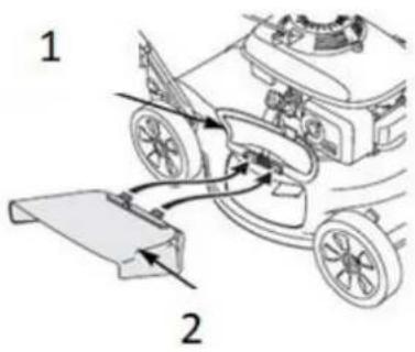
 | 2. Connection clutch and brake cableConnect the clutch cable (2) to the clutch handle and the brake cable (12) to the brake handle. |
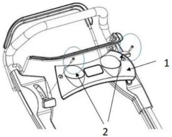 | 3. Assembly panelFasten panel (1) with two screws (2) to the handle. |
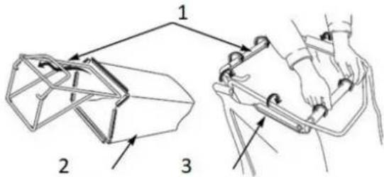 | 4. Assembly Grass CatcherPush the frame into the grass bag and fasten it with the clips. |
  | 5. Assembly Grass CatcherRaise the rear discharge guard (1) and remove the mulch plug if inserted, then hang the handle (2) of the collecting container.6. Assembly/Dismounting Mulch PlugThe mulching plug (2) is used to redesign the inside of the mower for more efficient mulching. Install and remove the mulching plug (1) by lifting the rear discharge guard (2) as shown. The mulch plug (1) will only fit in one direction.Remove the mulch plug (1) when using the grass collector. |
 | 7. Locking Rear Discharge FlapTo lock the rear discharge flap, use brackets as shown. |
 | 8. Assembly lateral discharge (only for ZI-BRM508)Raise the side guard (1) and mount the side discharge as shown. |
15.3 Checklist before Start-up
NOTICE

The use of paint thinners, petrol, aggressive chemicals or abrasives leads to material damage to the surfaces! Therefore use only mild detergents for cleaning!
- Clean the machine and remove dirt and grass if necessary.
- If the air filter is dirty, blow the filter cartridge from the inside by moving a jet of dry compressed air up and down. Continue until all dust has been removed. Replace the air filter with a new one if necessary.
- Check the carburettor for external dirt and dust and clean it with dry compressed air if necessary.
- Check the nuts and bolts for tightness, paying particular attention to the knife. (Screws or bolts loosened by vibrations can lead to accidents)
15.3.1 Checking/refilling engine oil
NOTICE

Too low an oil level will damage the engine and shorten the life of the machine. Therefore, check the engine oil level before each start and top up if necessary.

text_image
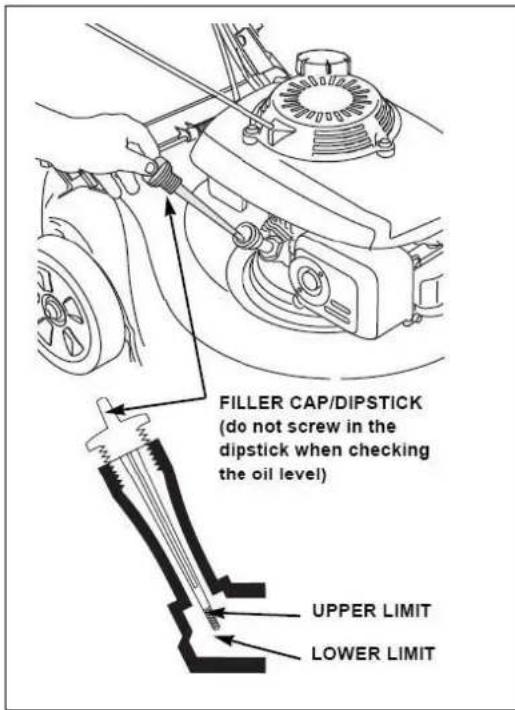
FILLER CAP/DIPSTICK (do not screw in the dipstick when checking the oil level) UPPER LIMIT LOWER LIMIT- To check the engine oil level, place the machine on a safe, level surface. Switch off the engine and allow the machine to stand for ten minutes so that the circulating oil can collect in the oil pan.
- Unscrew the oil dipstick and wipe it with a clean, lint-free cloth or a non-fibrous paper towel.
- Push the measuring rod back into the opening as far as it will go, but do not screw it in. (Make sure that the rod has really been pushed in completely - sometimes it cants itself).
- Pull out the oil dipstick again and read off the oil level. There are two markings for this - see illustration on the left.
- If the oil level is low, top up recommended oil to the upper limit (maximum filling volume according to technical data).
- Insert the oil dipstick again and tighten it.
15.3.2 Checking fuel tank level / Refuelling Fuel Tank
NOTICE

Observe the safety regulations for fuel control. Filter the fuel during refuelling to prevent foreign particles from entering the combustion chamber. Wipe up leaked fuel.
Process:
- Screw on the tank cap (sits on the fuel tank).
- Level check in the form of a visual inspection. If necessary, top up petrol with the appropriate octane number (RON 95) (maximum tank volume according to technical data).
- Close the filler cap tightly after refuelling.
16 OPERATION
Only put the machine into operation after you have read and understood the safety instructions and carried out the necessary measures before initial commissioning..
16.1 Informationen on Initial Start-up
NOTICE

The machine is delivered without engine oil and fuel. Make sure that this equipment is filled up before the machine is put into operation for the first time. The machine does not start until engine oil has been refilled to the upper limit (low oil lubrication)!
16.1.1 Test Run Initial Start-up
- Let the machine run idle for about 3 minutes.
- Watch out for abnormal noises.
- Pay attention to the exhaust fumes (too black, too white)?
16.1.2 Notes for the first 20 operating hours
In order to optimize the life expectancy of your machine, the following points should be observed:
- Spare the engine for the first 20 operating hours (this also applies to used engines after extensive maintenance). This means lower speed and lower maximum working load than during normal operation.
- Change the engine oil after the first 20 hours of operation.
16.2 Operating instructions
- Never tighten the cable while the engine is running. This will damage the motor.
- The pull mechanism for changing the motor speed is limited by an adjusting screw. This is factory set. Never change this setting on your own, you could overload the motor.
- Under no circumstances should you operate the machine on slopes of more than 20°, as even with an optimum oil level the engine may not be supplied with sufficient lubrication.
- In the direction of the forward movement of the machine and within a range of one meter around the machine, nobody but the operator must stand.
• Pay particular attention to the following particularly dangerous areas: - Special precautions must be taken when mowing on slopes. Only mow crosswise to the slope, never downwards or upwards, observing the maximum permissible slope angle.
- The cutting height can be adjusted by means of a lever on the machine, adjust it to the respective condition of the lawn to be worked.
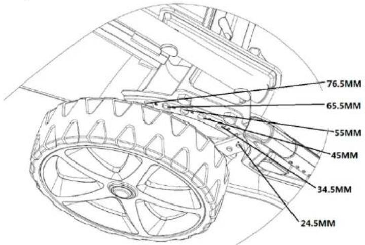
text_image
76.5MM 65.5MM 55MM 45MM 34.5MM 24.5MM16.3 Starting the Machine
ZI-BRM420
Cold Start
text_image
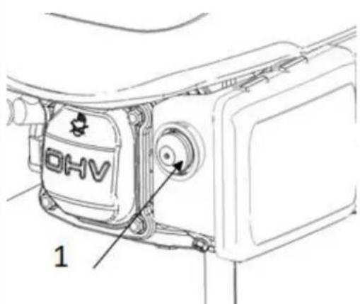
OHV 1When the engine is cold, press the primer button (1) before starting.
The following recommendation applies with regard to the number of button actuations depending on the outdoor temperature.
| Temperature | attempts |
| < 0°C | 3~4 |
| 0°C~10°C | 2~3 |
| 10°C~20°C | 1~2 |
| >20°C | 1 |
ZI-BRM508
Cold Start

text_image
ChokeBefore starting, push the choke lever to the foremost position.
text_image
Diagram showing two labeled mechanical or physical setups with numbered components, likely illustrating a grip or clamp mechanism.
text_image
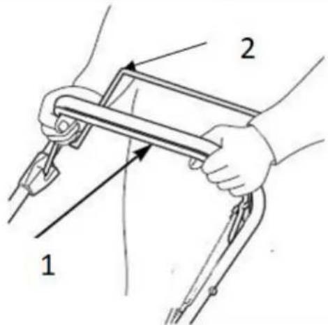
STARTER GRIP RUN- Pull the brake lever (1) towards the handle and hold it.
Note: Do not tighten the clutch lever (2) during starting, this will prevent the machine from moving forward.
-
Grasp the starter handle and pull it out slowly. The resistance becomes strongest at a certain point. This point corresponds to the compression point. Let the rope roll back a little from this point and then pull it out powerfully.
-
Put the choke lever in the "RUN" position after starting the engine.
 | 4. For best cut quality, always mow with the throttle lever in the "FAST" position. (When the blade rotates at the preset fast speed, it creates a strong fan action that lifts and cuts grass more efficiently.) |
 | 5. To start the forward movement, press the lever (1) in the direction of the handle.Note: Use the lever (1) for operating the machine only in its extreme positions (fully pressed on the handle for forward movement, in the starting position for no support of forward movement). This extends the life of the clutch mechanism. |
16.4 Stopping the machine
WARNING

The blade continues to rotate for a few seconds after the engine is stopped. To leave the mower unattended, disconnect the spark plug connector.
text_image
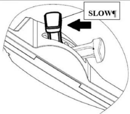
SLOW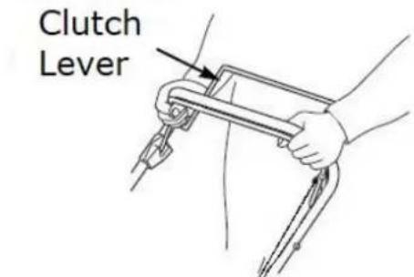
text_image
Clutch Lever
text_image
SLOW Clutch Lever-
Move throttle lever to position "SLOW".
-
Release clutch lever.

text_image
Brake Lever 3. Release brake lever17 MAINTENANCE
WARNING

Hot surfaces and rotating machine parts while the engine is running can cause serious injury or even death. Always stop the machine before carrying out any conversion, adjustment, cleaning or maintenance work, let it cool down and secure it against unintentional restarting.
17.1 Maintenance and Servicing Plan
| What to do? | frequency |
| Check fuel level | before each start-up |
| Check engine oil level | before each start-up |
| Control of the operating elements | before each start-up |
| Check for damaged parts | before each start-up |
| Checking for loose or lost screws | before each start-up |
| Change engine oil | First after 5h or 1 month, then every 3 months or 25h |
| Air filter cleaning/replacement | every 25h or 3 months |
| Spark plug test/replacement | every 200 h or 2 years |
| Fuelfilter cleaning | every 25h or 3 months |
The specified intervals refer to working under "normal" operating conditions. Depending on the load, a change/exchange may also be necessary at an earlier point in time.
17.2 Changing the Engine Oil
NOTICE

The machine is delivered without engine oil and fuel. Make sure that this operating resources are filled up before the machine is put into operation for the first time. The machine does not start until engine oil has been refilled to the upper limit (insufficient oil lubrication)!
text_image
FILLER CAP/DIPSTICK (do not screw in the dipstick when checking the oil level) UPPER LIMIT LOWER LIMITChange engine oil:
- Drain the used oil while the engine is warm. Warm oil drains quickly and completely.
- Wipe the oil filling area clean and then remove the oil filler cap/dipstick.
- Place a suitable container next to the mower to collect the waste oil and then tilt the mower to the right side. The waste oil will drain through the filler neck. Allow the oil to drain off completely.
- Fill in the recommended oil. Do not overfill! Wait a few minutes for the oil to settle in the engine before measuring the oil level.
17.3 Checking / Replacing blades
NOTICE

For the assembly/disassembly of the blade you need a torque wrench. After assembly, check that the blade screws are firmly tightened. Always wear protective gloves when working on the blade.
17.3.1 Checking the blade
- Tilt the mower to the right with the air filter side facing up. This helps to avoid fuel leaks and hard starting.
- Check the blade for damage, cracks and excessive rust or corrosion: a blunt blade can be sharpened, but a blade that is excessively worn, bent, cracked or otherwise damaged must be replaced.
17.3.2 Replacing the blade
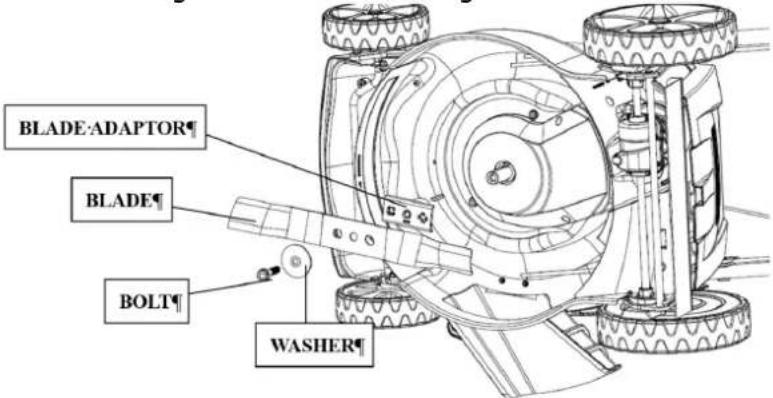
- Remove the screw with a socket wrench. Use a wooden block to prevent the blade from turning when the bolt is removed. Then remove the blade.
- Mount the blade with the screw and special washers. Be sure to mount the special washers with the concave side facing the blade and the convex side facing the bolt.
- Tighten the screw with a torque wrench. Use a wooden block to prevent the blade from turning when the screw is tightened.
text_image
BLADE:ADAPTOR BLADE BOLT WASHER17.4 Replacing and Cleaning the Grass Bag
17.4.1 Cleaning
Clean the grass sack with water from the garden hose and allow it to dry completely before reuse; a wet sack will clog quickly.
17.4.2 Replacing
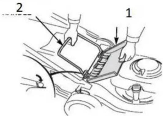
| BAG PLASTIC EDGE FRAME | 1. Remove the plastic edges from the frame and remove the frame from the bag. 2. Insert the frame into the new bag and clamp the plastic edges of the bag to the frame. |
17.5 Adjusting the clutch and brake cables
17.5.1 Adjusting the clutch cable
| clutch cable adjustment | If the clutch lever is loose, you should turn the clutch cable adjustment to tighten (see picture on the left). |
17.5.2 Brake cable adjustment
 Brake lever cable adjustment Brake lever cable adjustment | If the brake lever is loose, tighten the brake cable by turning it (see picture on the left). |
17.6 Cleaning the air filter
NOTICE

If the engine is operated with or without a damaged air filter, dirt will get into the engine, resulting in rapid engine wear.
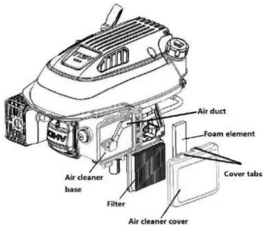
text_image
Air duct Foam element Cover tabs Air cleaner base Filter Air cleaner coverTo clean the air filter, proceed as follows:
- Press the clamps and remove the air filter cover.
- Remove the filter.
- Check filter and foam element and replace if damaged.
- Clean the filter by tapping it several times on a hard surface to remove dirt, or blow compressed air from the inside through the air filter.
- Never attempt to brush off dirt; brushing forces dirt into the fibers.
- Remove dirt from the inside of the air filter base and cover with a damp cloth. Ensure that no dirt enters the air duct leading to the carburetor.
- Remount the filter and cover.
17.7 Cleaning / Replacing the Spark Plug
NOTICE

A loose spark plug can overheat and damage the engine. Tightening the spark plug too much can damage the thread in the cylinder head.
For error-free operation, the contact surface of the candle in the cylinder head and the sealing ring of the candle must be clean and free of residues.
 CAP CAP | 1. Take off the spark plug cap and remove any dirt underneath. |
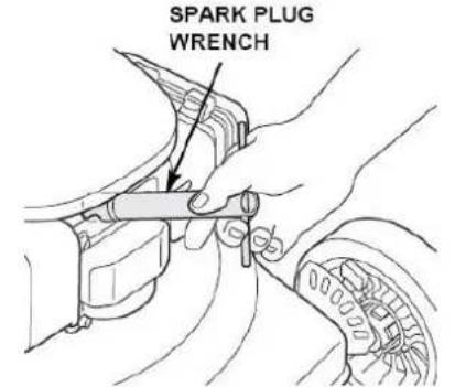 | 2. Remove the spark plug with a spark plug wrench.3. Check the spark plug. Replace it if the electrodes are worn out or if the insulator is torn or broken. |
 | 4. Measure the electrode gap of the spark plug with a suitable measuring device. The distance should be 0.7 - 0.8 mm. If necessary, correct the gap by carefully bending the side electrode with a suitable tool.5. Fit the spark plug cap. |
18 TRANSPORT
WARNING

Never lift or transport the machine with the engine running!
19 STORGAE
- To reduce the risk of fire, keep the engine, silencer, battery compartment and fuel tank free of grass, leaves or excessive grease.
- Allow the product to cool for at least 30 minutes before storage.
• Before storage, clean the mower thoroughly and store it in a dry, frost-free place. - Never store the mower with fuel in the tank inside a building where it can reach an open flame or spark.
• If the fuel tank needs to be emptied, this should be done outdoors.
If the machine is not used for a longer period of time (>30 days):
• Empty the oil or fuel tank.
- Remove the spark plug and pour a few drops of engine oil into the cylinder. Using a rope starter, turn the engine a few times so that the oil is well distributed inside the cylinder. (Clean spark plug before reuse!)
20 DISPOSAL

Do not dispose of your machine in residual waste. Contact your local authorities for information on available disposal options. If you buy a new vibratory plate or equivalent from your dealer, he is obliged in certain countries to dispose of your old machine properly.
21 TROUBLESHOOTING
WARNING

Hot surfaces and rotating machine parts while the engine is running can cause serious injury or even death. Switch off the machine before carrying out any troubleshooting work and secure it against unintentional restarting.
| Fault | Possible cause | Remedy |
| Motor does not start | No fuel | check fuel; refuel if necessary |
| wrong fuel; engine stored without prior emptying of fuel tank | empty the fuel tank and the carburetor. Fill up with fresh gasoline. | |
| spark plug defective, dirty or spark plug connector loose.spark plug wet with fuel (flooded engine) | check spark plug or spark plug connector.dry / clean or replace spark plug if necessary | |
| fuel filter clogged, carburettor malfunction, ignition malfunction, valve terminals, etc. | read operating manual, contact authorized service dealer if necessary; replace or repair defective components if necessary | |
| in cold condition | press primer button | |
| Motor has no or too little power | air filter elements clogged | clean or replace air filter elements |
| incorrect fuel; machine stored without appropriate treatment or emptying of fuel tank | empty fuel tank and carburetor; refuel with fresh fuel. | |
| fuel filter clogged, carburettor malfunction, ignition malfunction, valve clamps etc.. | read the operating instructions or take the machine to an authorised service dealer. Replace or repair defective components if necessary. |
22 AVANT-PROPOS (FR)
Cher client, chère cliente,
23.1.1 Restrictions techniques
text_image
Technical diagram of a mechanical assembly with labeled parts and cross-sectional views- Poignée de montage
natural_image
Diagram of a mechanical lever mechanism with directional arrows indicating movement (no text or symbols)text_image
Diagram showing two labeled mechanical or physical components with arrows indicating motion or force direction(EN) With ZIPPER spare parts you use spare parts that are ideally matched to each other. The fitting accuracy of the parts shortens their installation time and increases the service life of the machine.
NO TE
The installation of parts other than original spare parts leads to the loss of the
guarantee! Therefore, when replacing components/parts, only use original spare parts! When ordering spare parts, please use the service form at the end of this manual. Always state machine type, spare part number and designation. In order to avoid misunderstandings, we recommend enclosing a copy of the spare part drawing with the spare part order, on which the required spare parts are clearly marked.
You will find the ordering address under customer service addresses in the foreword to this documentation.
| Pos.no. | Description | Qty | Pos.no. | Description | Qty |
| A part | C-11 | Lock Ring | 2 | ||
| A-1 | Foam Pipe | 1 | C-12 | Rear Cover | 1 |
| A-2 | Clutch Lever | 1 | C-13 | Rear Cover Spring | 1 |
| A-3 | Brake Lever | 1 | C-14 | Rear Cover Shaft | 1 |
| A-4 | Limiting Stopper | 1 | C-15 | Front Plastic Face | 1 |
| A-5 | Upper Handle | 1 | C-16 | Screw | 4 |
| A-6 | Bolt | 2 | D part | ||
| A-7 | Flat Washer | 4 | D-1 | Height Adjustment Handle | 1 |
| A-8 | Knob | 4 | D-2 | Rear Wheel Shaft Assy | 1 |
| A-9 | Rope Guide | 1 | D-3 | 7" inner wheel cover | 2 |
| A-10 | Handle Plug | 2 | D-4 | Spring Washer | 4 |
| A-11 | Lower handrail | 2 | D-5 | Ball Bearing | 4 |
| A-12 | Cable Support | 1 | D-6 | 7" Wheel | 2 |
| A-13 | Bolt | 2 | D-7 | Nut | 2 |
| A-14 | Bolt | 2 | D-8 | 7" Wheel Cover | 2 |
| A-15 | Nut | 2 | D-9 | Gear box | 1 |
| A-16 | Nut | 1 | D-10 | Spring | 1 |
| A-17 | Cable Fixing Clamp | 1 | D-11 | Pin | 2 |
| A-18 | brake cable | 1 | D-12 | Shaft Sleeve | 1 |
| A-19 | Cluch cable | 1 | D-13 | Bolt | 4 |
| A-20 | Bolt | 1 | D-14 | Flat Washer | 2 |
| B part | D-15 | Lock Ring | 4 | ||
| B-1 | Y80V | 1 | D-16 | Left Gear | 1 |
| B-2 | Screw Cap | 2 | D-17 | Belt Li620 | 1 |
| B-3 | Belt Cover | 1 | D-18 | Shaft Sleeve | 1 |
| B-4 | Bolt | 3 | D-19 | Right Gear | 1 |
| B-5 | Screw | 2 | D-20 | Front Wheel Shaft | 1 |
| B-6 | Flat Washer | 1 | D-21 | Shaft Sleeve | 4 |
| B-7 | Flat Key | 1 | D-22 | 6"wheel | 2 |
| B-8 | Blade adapter | 1 | D-23 | 6" Outer Wheel Cover | 2 |
| B-9 | 17" Blade | 1 | D-24 | Bolt | 2 |
| B-10 | Blade Washer | 1 | D-25 | Nut | 2 |
| B-11 | Blade Bolt | 1 | D-26 | Flat Washer | 1 |
| C part | D-27 | Split Pin | 2 | ||
| C-1 | Bolt | 2 | D-28 | Height Adjustment Connecting R | 1 |
| C-2 | Height Adjustment Plate | 1 | D-29 | Precursor bushing | 2 |
| C-3 | Nut | 2 | E part | ||
| C-4 | Right Bracket | 1 | E-1 | Metal Bracket | 1 |
| C-5 | Bolt | 4 | E-2 | Flat Washer | 4 |
| C-6 | Nut | 4 | E-3 | Screw | 4 |
| C-7 | Deck | 1 | E-4 | Cover Plate | 1 |
| C-8 | Mulch plug | 1 | E-5 | Plastic Cover | 1 |
| C-9 | Cable Sleeve | 1 | E-6 | Fabric Bag | 1 |
| C-10 | Left Bracket | 1 |
31.3 Explosionszeichnung / Explosion drawing ZI-BRM508 / Vue éclatée

text_image
A B C D E F ZI-BRM508 MODEL EAN: 9120039233840 1 2 3 4 5 6 7 8 9 10 11 12 13 14 15 16 17 18 19 20 21 22 23 24 25 26 27 28 29 30 31 32 33 34 35 36 37 38 39 40 41 42 43 44 45 46 47 48 49 50 51 52 53 54 55 56 57 58 59 60 61 62 63 64 65 66 67 68 69 70 71 72 73 74 75 76 77 78 79 80 81 82 83 84 85 86 87 88 89 90 91 92 93 94 95 96 97 98 99 100| Pos no. | Description | Qty | Pos no. | Description | Qty |
| A part | D-16 | plug | 2 | ||
| A-1 | Plastic Decoration | 1 | D-17 | Rear Cover | 1 |
| A-2 | Clutch Lever | 1 | D-18 | Rear Cover Spring | 1 |
| A-3 | Brake Lever | 1 | D-19 | Rear Cover Shaft | 1 |
| A-4 | Limiting Stopper | 1 | D-20 | front parts | 1 |
| A-5 | Plastic Decoration | 1 | D-21 | Screw | 4 |
| A-6 | Foam Pipe | 1 | D-22 | Washer L | 1 |
| A-7 | Upper Handle | 1 | D-23 | Washer R | 1 |
| A-8 | Fixed Plate | 1 | D-24 | Nut | 2 |
| A-9 | Brake cable | 1 | D-25 | Side Discharge Bracket | 1 |
| A-10 | Clutch cable | 1 | D-26 | Screw | 2 |
| A-11 | Lower Handle | 1 | D-27 | Side Discharge Cover Shaft | 1 |
| A-12 | Bolt | 4 | D-28 | Side Discharge Cover Spring | 1 |
| A-13 | Flat Washer | 4 | D-29 | Screw | 2 |
| A-14 | Knob | 4 | D-30 | Cover Plate | 1 |
| A-15 | Rope Guide | 1 | D-31 | Spring | 1 |
| A-16 | Nut | 1 | D-32 | Side Discharge Cover | 1 |
| A-17 | Cable Support | 2 | D-33 | Lock | 1 |
| A-18 | Bolt | 2 | D-34 | Side-Discharge Guiding Board | 1 |
| A-19 | Nut | 2 | D-35 | Maintenance windows | 1 |
| A-20 | Handle Plug | 2 | E part | ||
| B part | E-1 | Height Adjustment Handle | 1 | ||
| B-1 | Upper Cover of Left Panel | 1 | E-2 | Rear Wheel Shaft Assy | 1 |
| B-2 | Screw | 2 | E-3 | Inner Wheel Cover | 2 |
| B-3 | Spring | 2 | E-4 | Spring Washer | 4 |
| B-4 | Handle | 1 | E-5 | Screw | 2 |
| B-5 | Cable | 1 | E-6 | Bearing | 4 |
| B-6 | Nut | 6 | E-7 | 11" Wheel | 2 |
| B-7 | Bolt | 1 | E-8 | Flat Washer | 2 |
| B-8 | Screw | 2 | E-9 | Nut | 4 |
| B-9 | Screw | 2 | E-10 | 11" Outer Wheel Cover | 2 |
| B-10 | Lower Cover of Left Panel | 1 | E-11 | Split Pin | 1 |
| B-11 | Screw | 4 | E-12 | Belt | 1 |
| B-12 | Screw | 6 | E-13 | Gearbox | 1 |
| B-13 | Handle panel | 1 | E-14 | Fixing plate | 1 |
| B-14 | Upper Cover of Right Panel | 1 | E-15 | Pin | 2 |
| B-15 | Bush | 1 | E-16 | Nut | 5 |
| B-16 | Fixed Plate | 1 | E-17 | Shaft Sleeve | 2 |
| B-17 | Plastic Grip | 1 | E-17-1 | ball bearing | 2 |
| D-18 | Handle Assy | 1 | E-18 | Screw | 4 |
| B-19 | Spring | 1 | E-19 | Washer | 4 |
| B-20 | Cable | 1 | E-20 | Flat Washer | 2 |
| B-21 | Lower Cover of Right Panel | 1 | E-21 | Left Gear | 1 |
| C part | E-22 | Right Gear | 1 | ||
| C-1 | Y173V | 1 | E-23 | Front Wheel Shaft | 1 |
| C-2 | Screw | 3 | E-24 | Nut | 5 |
| C-3 | Flat Key | 1 | E-25 | Screw | 5 |
| C-4 | Blade adapter | 1 | E-26 | Nut | 1 |
| C-5 | Screw Cap | 2 | E-27 | Bearing | 4 |
| C-6 | Belt Cover | 1 | E-28 | 8"Wheel | 2 |
| C-7 | Screw | 2 | E-29 | 8" Outer Wheel Cover | 2 |
| C-8 | Belt Cover Plate | 1 | E-30 | Height Adjustment Spring | 1 |
| C-9 | Belt Cover Plate | 1 | E-31 | Height Adjustment Connectin | 1 |
| C-10 | Screw | 2 | E-32 | Shaft Sleeve | 4 |
| C-11 | 20" Blade | 1 | E-33 | Precursor bushing | 4 |
| C-12 | Blade Washer | 1 | E-34 | Nut | 4 |
| C-13 | Blade Bolt | 1 | E-35 | Spring | 1 |
| D part | E-36 | fixed plate | 1 | ||
| D-1 | Bolt | 4 | E-37 | fixed plate | 1 |
| D-2 | Height Adjustment Plate | 1 | E-38 | Bolt | 2 |
| D-3 | Right Bracket | 1 | E-39 | Idle pulley | 2 |
| D-4 | Nut | 4 | E-40 | Bearing | 3 |
| D-5 | deck | 1 | E-41 | Bolt | 1 |
| D-6 | Mulching Plug | 1 | E-42 | Screw | 1 |
| D-7 | Cable Sleeve | 1 | F part | ||
| D-8 | Seal Ring | 1 | F-1 | Metal Bracket | 1 |
| D-9 | Washing Linker | 1 | F-2 | Flat Washer | 4 |
| D-10 | Plastic Nut | 1 | F-3 | Screw | 2 |
| D-11 | Left Bracket | 1 | F-4 | Plastic Cover | 1 |
| D-12 | Rear Cover Support | 2 | F-5 | Cover Plate | 1 |
| D-13 | Screw | 3 | F-6 | Indicated Board | 1 |
| D-14 | Rear Cover Pedestal | 1 | F-7 | Fabric bag | 1 |
| D-15 | Nut | 3 |
Company ZIPPER Maschinen GmbH grants for mechanical and electrical components a warranty period of 2 years for amateur use; and warranty period of 1 year for professional use, starting with the purchase of the final consumer. In case of defects during this period, which are not excluded by paragraph 3, ZIPPER will repair or replace the machine at its own discretion.
2.) Report:
In order to check the legitimacy of warranty claims, the final consumer must contact his dealer. The dealer has to report in written form the occurred defect to ZIPPER. If the warranty claim is legitimate, ZIPPER will pick up the defective machine from the dealer. Returned shippings by dealers which have not been coordinated with ZIPPER, will not be accepted and refused.
3.) Regulations:
a) Warranty claims will only be accepted, when a copy of the original invoice or cash voucher from the trading partner of ZIPPER is enclosed to the machine. The warranty claim expires if the accessories belonging to the machine are missing.
b) The warranty does not include free checking, maintenance, inspection or service works on the machine. Defects due to incorrect usage of the final consumer or his dealer will not be accepted as warranty claims either. Some examples: usage of wrong fuel, frost damages in water tanks, leaving fuel in the tank during the winter, etc.
c) Defects on wear parts are excluded, e.g. carbon brushes, collection bags, knives, cylinders, cutting blades, clutches, sealings, wheels, saw blades, splitting crosses, riving knives, riving knife extensions, hydraulic oils, oil/air/fuel filters, chains, spark plugs, sliding blocks, etc.
d) Also excluded are damages on the machine caused by incorrect or inappropriate usage, if it was used for a purpose which the machine is not supposed to, ignoring the user manual, force majeure, repairs or technical manipulations by not authorized workshops or by the customer himself, usage of non-original ZIPPER spare parts or accessories.
e) After inspection by our qualified personnel, resulted costs (like freight charges) and expenses for not legitimated warranty claims will be charged to the final customer or dealer.
f) In case of defective machines outside the warranty period, we will only repair after advance payment or dealer's invoice according to the cost estimate (incl. freight costs) of ZIPPER.
g) Warranty claims can only be granted for customers of an authorized ZIPPER dealer who directly purchased the machine from ZIPPER. These claims are not transferable in case of multiple sales of the machine.
4.) Claims for compensation and other liabilities:
The liability of company ZIPPER is limited to the value of goods in all cases. Claims for compensation because of poor performance, lacks, damages or loss of earnings due to defects during the warranty period will not be accepted. ZIPPER insists on its right to subsequent improvement of the machine.
35 GARANTIE (FR)
1.) Garantie :
Please describe amongst others in the problem: What has cause the problem/defect, what was the last activity before you noticed the problem/defect? For electrical problems: Have you had checked you electric supply and the machine already by a certified electrician?
3. Bitte beachten
/ Additional information
INCOMPLETELY FILLED SERVICE FORMS CANNOT BE PROCESSED! FOR GUARANTEE CLAIMS PLEASE ADD A COPY OF YOUR ORIGINAL SALES / DELIVERY RECEIPT OTHERWISE IT CANNOT BE ACCEPTED. FOR SPARE PART ORDERS PLEASE ADD TO THIS SERVICE FORM A COPY OF THE RESPECTIVE EXPLODED DRAWING WITH THE REQUIRED SPARE PARTS BEING MARKED CLEARLY AND UNMISTAKABLE. THIS HELPS US TO IDENTIFY THE REQUIRED SPARE PARTS FASTLY AND ACCEL- LERATES THE HANDLING OF YOUR INQUIRY.