
ZIWP400TN - Saw Zipper - Free user manual and instructions
Find the device manual for free ZIWP400TN Zipper in PDF.

| Product type | Electric log saw |
| Brand | Zipper |
| Model | ZIWP400TN |
| Power supply | 230 V ~ 50 Hz |
| Residual current protection | Circuit breaker 0.03 A |
| Maximum extension cord length | 10 m with cross-section ≥ 2.5 mm² |
| Operating temperature | +5 °C to +40 °C |
| Storage temperature | -20 °C to +55 °C |
| Maximum relative humidity | 65% |
| Main functions | Cutting wood logs and logs |
| Safety | Blade guard, on/off switch, emergency stop |
| Maintenance | Blade sharpening and replacement, regular cleaning |
| Spare parts | Available via online catalog |
| Warranty (non-commercial use) | 2 years |
| Warranty (commercial use) | 1 year |
| Blade standard | EN 847-1 |
| Intended use | Wood without foreign objects (nails, etc.) |
Frequently Asked Questions - ZIWP400TN Zipper
User questions about ZIWP400TN Zipper
0 question about this device. Answer the ones you know or ask your own.
Ask a new question about this device
Download the instructions for your Saw in PDF format for free! Find your manual ZIWP400TN - Zipper and take your electronic device back in hand. On this page are published all the documents necessary for the use of your device. ZIWP400TN by Zipper.
USER MANUAL ZIWP400TN Zipper
natural_image
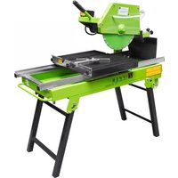
Green and black industrial machine with 'ZIPPER' branding, mounted on a stand (no visible text or symbols beyond branding)CE
ZI-WP400TN
EAN : 9120039234427

1 INHALT / INDEX / SOMMAIRE
1 INHALT / INDEX / SOMMAIRE , , , 2
12.1 Intended use of the machine 25
12.1.1 Technical Restrictions 25
12.1.2 Prohibited Use / Forseeable Misuse....25
12.2 User Requirements 25
12.3 General safety instructions 26
12.4 Electrical safety 26
12.5 Special safety instructions for this machine.... 27
12.6 Hazard warnings.... 27
13 TRANSPORT 28
14 ASSEMBLY 28
14.1 Checking scope of delivery.... 28
14.2 The workplace.... 28
14.3 Assembly 29
14.4 Electrical connection.... 35
15 OPERATION 35
15.1 Work before start-up 35
15.2 Operating 35
15.2.1 Start/Stop 35
15.2.2 Workflow....35
16 MAINTENANCE 36
16.1 Sharpening the saw blade.... 36
16.2 Changing the saw blade 36
16.3 Cleaning 38
16.4 Storage 38
16.5 Disposal 38
17 TROUBLESHOOTING 39
18 AVANT-PROPOS (FR) 40
19 SECURITE 41
19.1 Utilisation conforme....41
19.1.1 Restrictions techniques 41
19.1.2 Applications interdites / Mauvaises applications dangereuses....41
CONFORMITY / DÉCLARATION DE CONFORMITÉ UE 60
EN CE-Conformal! - This product complies with the EC-directives.
READ THE MANUAL! Read the user and maintenance manual carefully and get familiar with the controls in order to use the machine correctly and to avoid injuries and machine defects.


EN Caution! Risk of injury! Failure to keep your hands away from the saw blade will result in serious personal injury.
EN It is forbidden to remove or tamper with the protection devices and safety devices!
EN Keep children and unauthorized persons away!
EN Before working on the device, disconnect the mains plug!
natural_image
Three blue circular icons representing head, foot, and helmet symbols (no text or labels)
EN Wear personal protective equipment!
EN Warning signs and/or stickers on the machine which are illegible or have been removed must be replaced immediately!
natural_image
Technical diagram of a mechanical linkage system with a circular component and supporting beams (no text or symbols)natural_image
Technical line drawing of a mechanical device with a numbered component (5), no visible text or symbolsThis operating manual contains information and important notes for safe commissioning and handling of the Log Saw ZI-WP400TN, hereinafter referred to as "machine".

The manual is an integral part of the machine and must not be removed. Keep it for later use in a suitable place, easily accessible to users (operators), protected from dust and moisture, and enclose it with the machine if it is passed on to third parties!
Please pay special attention to the chapter Safety!
Due to the constant further development of our products, illustrations and contents may differ slightly. If you notice any errors, please inform us.
Technical changes reserved!
Check the goods immediately after receipt and make a note of any complaints on the consignment note when the delivery person takes them over!
Transport damage must be reported separately to us within 24 hours.
Zipper cannot accept any liability for transport damage not noted.
Copyright
© 2021
This documentation is protected by copyright. All rights reserved! In particular the reprint, the translation and the removal of photos and illustrations will be prosecuted.
Court of jurisdiction is the regional court Linz or the competent court for 4707 Schlüsslberg, Austria!
Customer service contact
This section contains information and important notes on safe start-up and handling of the machine.

For your own safety, read these operating instructions carefully before putting the machine into operation. This will enable you to handle the machine safely and prevent misunderstandings as well as personal injury and damage to property. In addition, observe the symbols and pictograms used on the machine as well as the safety and hazard information!
12.1 Intended use of the machine
The machinery is intended exclusively for the following operations:
For cutting round wood, logs and other woody materials.
Information on the condition of the workpieces:
- There must be no foreign objects, such as nails, in the workpiece!
- Only one workpiece may be machined at a time, regardless of its dimensions!
- It is not allowed to process several and also no bundles of cut material.
- To prevent wedging and recoil of the cut material, bent cut material must always be placed in the log carriage so that the outer edge faces the machine.
ZIPPER-MASCHINEN assumes no responsibility or warranty for any other use or use beyond this and for any resulting damage to property or injury.
12.1.1 Technical Restrictions
The machine is intended for use under the following ambient conditions:
Relative humidity: max. 65 %
Temperature (for operation) +5°C bis +40°C
Temperature (for storage and/or transport) -20°C bis +55°C
12.1.2 Prohibited Use / Forseeable Misuse
- Operating the machine without adequate physical and mental aptitude
- Operating the machine without knowledge of the operating instructions
- Changes in the design of the machine
- Remove the safety markings attached to the machine
- Modify, circumvent or disable the safety devices of the machine
- Operating the machine in a potentially explosive environment (Machine can generate ignition sparks during operation)
- Operating the machine outside the technical limits specified in this manual
- Machining of materials with dimensions outside the limits specified in these instructions.
- Use of tools that do not comply with the safety requirements of the standard for machine tools for woodworking (EN847-1).
- Use of saw blades made of HSS steel.
- Use of saw blades with a lower max. speed than the machine.
The improper use or disregard of the versions and instructions described in this manual will result in the voiding of all warranty and compensation claims against Zipper Maschinen GmbH.
12.2 User Requirements
The machine is designed for operation by one person. The physical and mental aptitude as well as knowledge and understanding of the operating instructions are prerequisites for operating the machine. Persons who, because of their physical, sensory or mental abilities or their inexperience or ignorance, are unable to operate the machinery safely must not use it without supervision or instruction from a responsible person.
Please note that local laws and regulations may determine the minimum age of the operator and restrict the use of this machine!
Put on your personal protective equipment before working on the machine.
Work on electrical components or equipment may only be carried out by a qualified electrician or under the instruction and supervision of a qualified electrician.
12.3 General safety instructions
To avoid malfunctions, damage and health hazards when working with the machine, the following points must be observed in addition to the general rules for safe working:
- Before start-up, check the machine for completeness and function. Only use the machine if the guards and other non-parting guards required for machining have been fitted, are in good operating condition and have been properly maintained.
- Choose a level, vibration-free, non-slip surface for the installation location.
- Ensure sufficient space around the machine!
- Ensure sufficient lighting conditions at the workplace to avoid stroboscopic effects.
- Ensure a clean working environment.
- Only use perfect tools that are free of cracks and other defects (e.g. deformations).
- Remove tool keys and other adjustment tools before switching on the machine.
- Keep the area around the machine free of obstacles (e.g. dust, chips, cut parts, etc.).
- Check the strength of the machine connections before each use.
- Never leave the running machine unattended. Switch off the machine before leaving the working area and secure it against unintentional or unauthorised recommissioning.
- The machine may only be operated, serviced or repaired by persons who are familiar with it and who have been informed of the hazards arising from this work.
- Ensure that unauthorised persons maintain a safe distance from the machine and keep children away from the machine.
- When working on the machine, never wear loose jewellery, loose clothing, ties or long, open hair.
- Hide long hair under hair protection.
- Wear close-fitting protective clothing and suitable protective equipment (eye protection, dust mask, ear protection; gloves only when handling tools).
- Hide long hair under hair protection.
• Always work with care and the necessary caution and never use excessive force.
- Do not overload the machine!
- Do not work on the machine if it is tired, not concentrated or under the influence of medication, alcohol or drugs!
- Do not use the machine in areas where vapours from paints, solvents or flammable liquids represent a potential danger (danger of fire or explosion!).
- Do not smoke in the immediate vicinity of the machine (fire hazard)!
- Shut down the machine and disconnect it from the power supply before carrying out any adjustment, conversion, cleaning, maintenance or repair work. Before starting any work on the machine, wait until all tools or machine parts have come to a complete standstill and secure the machine against unintentional restarting.
12.4 Electrical safety
- Improper use of extension cords may cause inefficient operation of the machine, resulting in overheating. Make sure that the extension cord is not longer than 10 m and its cross-section is not less than 2.5 mm 2 to allow sufficient current flow to the motor.
- Avoid using free and insufficiently insulated connections. Connections must be made with appropriate material suitable for outdoor use.
- A damaged or tangled cable increases the risk of electric shock. Handle the cable with care. Never use the cable to carry, pull or disconnect the power tool. Keep the cable away from heat, oil, sharp edges or moving parts.
- Proper plugs and sockets reduce the risk of electric shock.
- Water entry into machine increases the risk of electric shock. Do not expose machine to rain or moisture.
- The machine may only be used in humid environments if the power source is protected by a residual current circuit breaker.
- Do not use the power tool if it cannot be turned on and off with the ON-OFF-switch.
12.5 Special safety instructions for this machine
- When using milling tools with a diameter of ≥ 16 mm and circular saw blades, these must comply with EN 847-1:2013 and EN 847-2:2013; tool carriers must comply with EN 847-3:2013.
- Excessive noise can cause hearing damage and temporary or permanent hearing loss. Wear hearing protection certified to health and safety regulations to limit noise exposure.
- Replace cracked and deformed saw blades immediately, they cannot be repaired.
- Use saw blades that are clean and sharpened, they are less prone to failure and are easier to guide.
- Never attempt to cut logs that contain nails, wire or debris. Branches must be cut flush with the trunk.
- Always maintain a secure standing position and balance. Never stand on the machine. Serious injury can occur if the machine tips over or if the cutting tool is accidentally touched. Do not keep objects above or near the machine that someone could stand on to reach the machine.
- Do not attempt to load or unload logs until the machine has stopped.
- Do not remove residual pieces or other parts of the workpiece from the cutting area while the machine is running, unless you use a push stick.
- Keep your hands away from all moving parts.
- Do not grasp around the saw blade with both hands while the machine is running.
- Avoid awkward cutting operations and hand positions where a sudden slippage could cause your hand to get caught at the saw blade.
- Never deposit logs to be split in such a way that you have to reach over the machine.
- Operate the control handle with your hands only. Never use your foot, knee or any other extension tool.
- Never attempt to free a jammed saw blade without first turning off the machine.
12.6 Hazard warnings
Despite their intended use, certain residual risks remain. Due to the structure and construction of the machine, hazardous situations may occur when handling the machines:
DANGER

A safety instruction designed in this way indicates an imminently hazardous situation which, if not avoided, will result in death or serious injury.
WARNING

Such a safety instruction indicates a potentially hazardous situation which, if not avoided, may result in serious injury or even death.
CAUTION

A safety instruction designed in this way indicates a potentially hazardous situation which, if not avoided, may result in minor or moderate injury.
NOTICE

A safety note designed in this way indicates a potentially dangerous situation which, if not avoided, may result in property damage.
Irrespective of all safety regulations, their sound common sense and corresponding technical suitability/training are and remain the most important safety factor in the error-free operation of the machine. Safe working depends first and foremost on you!
13 TRANSPORT
For proper transport, follow the instructions and information on the transport packaging regarding centre of gravity, attachment points, weight, means of transport to be used and prescribed transport position, etc.
Transport the machine in its packaging to the place of installation. When lifting, carrying and depositing the load, make sure that you are in the correct posture:
- Lifting, Depositing
Ensure stability when lifting / setting down (legs hip width).
Lift / lower load with bent knees and straight back (like weightlifter).
Do not lift / lower the load jerkily.
- Carrying
Carry load with both hands as close to body as possible.
Carry load with straight back.
14 ASSEMBLY
14.1 Checking scope of delivery
Check the machine immediately after delivery for transport damage and missing parts.
14.2 The workplace
Choose a suitable place for the machine. Pay attention to the safety requirements and the dimensions of the machine. The selected location must ensure a suitable connection to the electrical supply. Make sure that the machine is placed on a solid and level surface and that the ground can support the load of the machine. The machine must be levelled at all support points. It is also necessary to guarantee a distance of at least 0.8 m around the machine. The necessary distance for the feeding of long workpieces must be provided.

natural_image
Technical diagram of a mechanical linkage system with a circular component and force arrows (no text or symbols)Anchoring on level ground
Use four bolts to secure your machine to the ground. Due to the different ground conditions, these are not included in the delivery content. Select the correct bolt type for your soil conditions.
14.3 Assembly
The machine was disassembled for transport and must be assembled as shown below. Before commissioning, check all screw connections for tightness and tighten them if necessary.
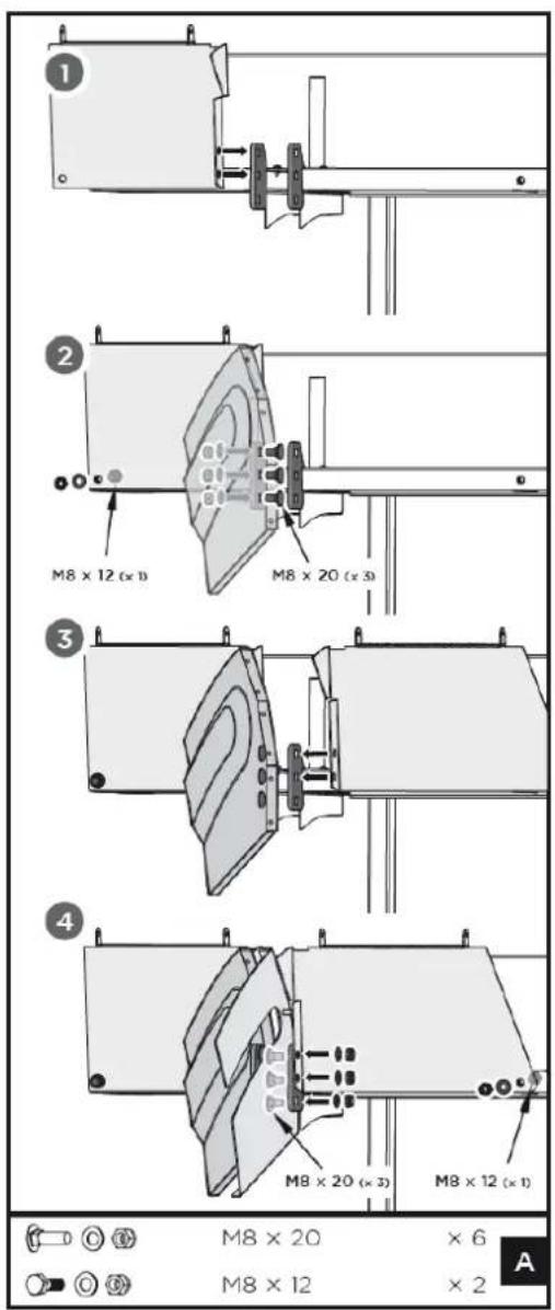
1. Assembly saw blade guard 1
Place the back plate 1 against the outside of the connection part on the log carriage and align its two holes with the upper two holes of the connection part as shown in Fig. A, Pic. 1.
Fix the back plate 1 to the table by using one M8×12 screw, a washer and a nut as shown in Fig. A, Pic. 2.
Place the saw blade guard 1 against the inner side of the same connecting part, align the holes and connect the saw blade guard 1, the connecting part and the back plate 1 by using three M8×20 screws, washers and nuts.
Repeat the same assembly steps on the other side for back plate 2 and saw blade guard 2, as shown in Fig. A, Pic. 3 & 4.

2. Assembly handle
Attach the handle to the back of the log carriage. Fix it with two M8×25 screws and locknuts as shown in Fig. B. Screw the M5×20 wing screw into the hole at the upper right corner.
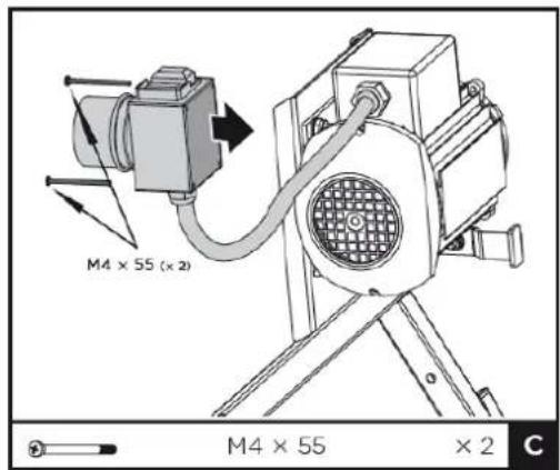
3. Assembly ON-OFF switch
Fix the ON-OFF switch to the motor plate with M4×55 screws as shown in Fig. C.
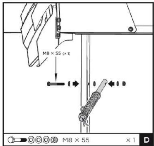
4. Assembly return spring
Fix one end of the guide pipe with return spring to the left leg using M8×55 bolts, washers and locknut as shown in Fig. D.

5. Connecting pivoting log carriage and base frame
Place the pivoting log carriage on the ground with the legs inside the base frame and put one end of the cross brace to the outside as shown in Fig. E.
Secure them using M8×40 bolts, washers and lock nuts on both sides.
Fix the other end of the cross brace from the inner side of the base frame using M8×70 bolts, washers and lock nuts on both sides.
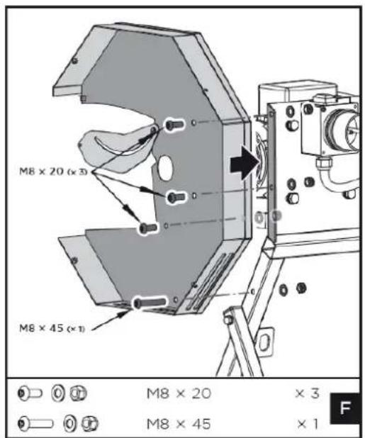
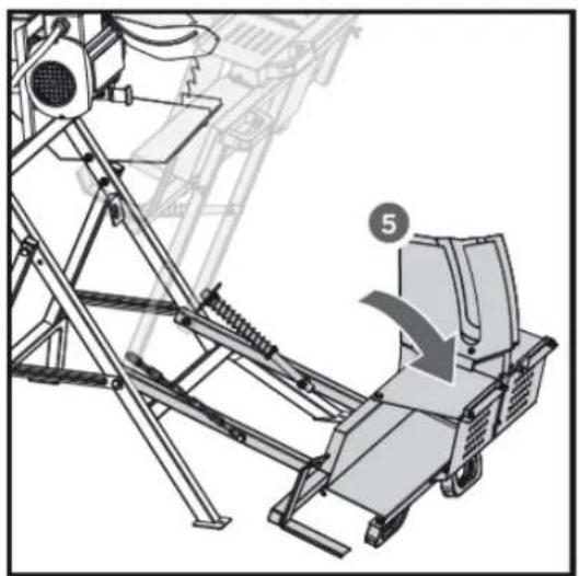
6. Assembly inner saw blade cover
Slide the shaft through the centre hole of the inner saw blade cover and align the other holes with those on the motor plate as shown in Fig. F.
Secure the shaft with three M8×20 screws, washers and locknuts on the upper side and one M8×45 screw, washer and locknut on the lower side.
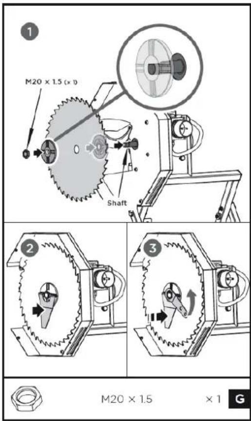
7. Assembly saw blade
CAUTION

When handling circular saw blades when changing tools, please use safety gloves to avoid risk of injury.
Slide the rear saw blade flange onto the motor shaft.
CAUTION

Make sure that the saw blade is inserted in the correct position. The arrow on the saw blade must point in the direction of the operating side!
Place the saw blade together with the front clamping flange on the rear flange and secure it with the nut M20×1.5 as shown in Fig. G, Pic. 1.
Tighten the nut with the saw blade wrench by holding the front clamping flange with the face wrench in order to stop back as shown in Fig. G, Pic. 2 & 3.
NOTICE

Please note! Always keep the two special keys properly.
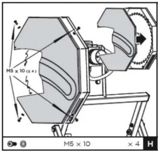
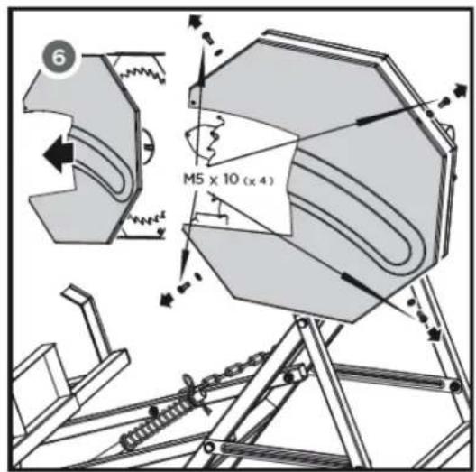
8. Assembly outer saw blade cover
Fix the outer saw blade cover to the inner cover using four M5×10 cross-head screws and washers as shown in Fig. H.
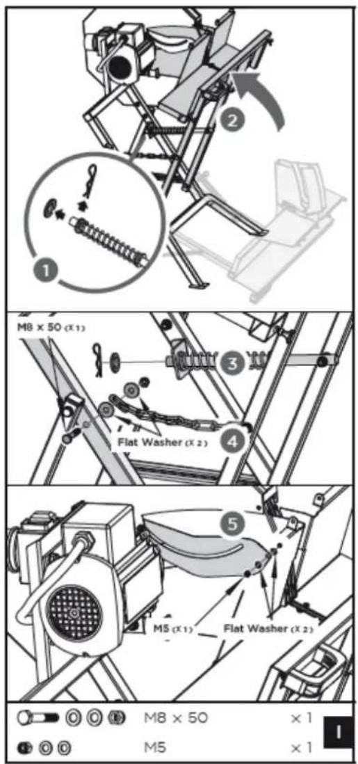
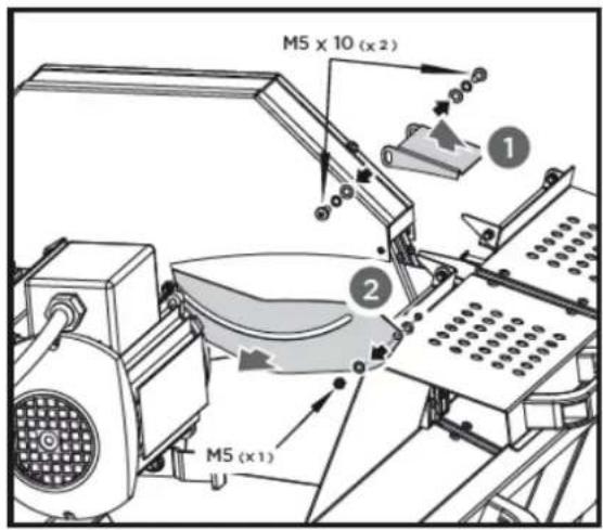
9. Fixing return spring and Chain
Take the cotter pin and washer out of the guiding pipe with spring as in Fig. I, step 1.
Move the log carriage to the base frame until the open end of the guiding pipe is inserted into the angle part at the base frame, as Fig. I, step 2.
Secure the pipe by using a washer and cotter pin as shown in Fig. I, step 3.
Fix the open end of the chain to the base frame at the left side by using a M8×50 screw, two washers and a nut as shown in Fig. I, step 4.
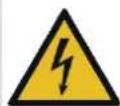
Guard plate of the inner saw blade cover
Install the guard plate of the inner saw blade cover on the saw blade guard by using a M5 nut and two washers as shown in Fig. I, step 5.

10. Assembly limit plate
Install the limit plate and fasten it with two M5×10 screws and washers as shown in Fig. J
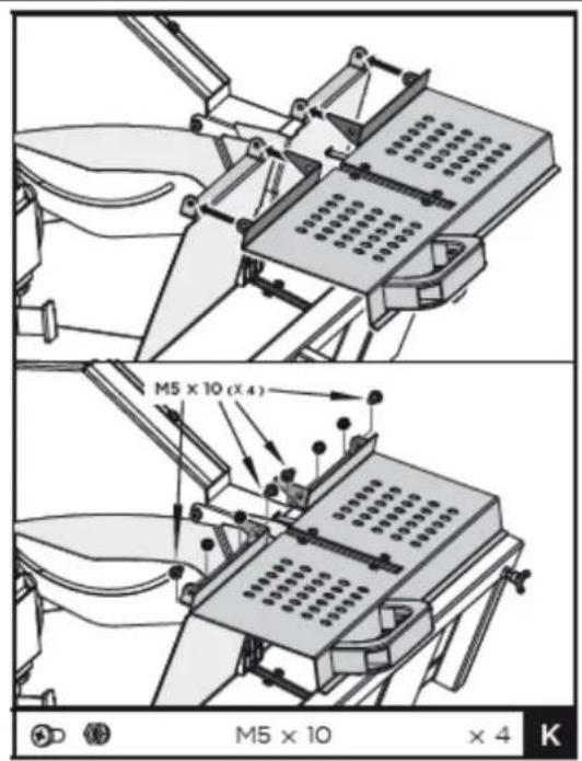
11. Assembly top guard
Install the top guard with four M5×10 screws and lock nuts as shown in Fig. K.

12. Assembly log carriage extension
Loosen the M5×20 wing screw on the rear side of the log carriage until the log carriage extension can be inserted into the opening. Slide the log carriage extension into the channel and align it correctly. Then fix it with the wing screw.
14.4 Electrical connection
- Connect the machine to a standard 230V ± 10% (50Hz ± 1Hz) power supply equipped with protections for undervoltage, overvoltage, overcurrent and a residual current device (RCD) with a maximum residual current of 0.03A.
- The plug of the machine must fit into the socket. The plug must not be modified in any way. Do not use adapter plugs together with protectively earthed machines. Unmodified plugs and matching sockets reduce the risk of electric shock.
- Only use extension cords that are also suitable for outdoor use. Using an extension cord suitable for outdoor use reduces the risk of electric shock.
15 OPERATION
15.1 Work before start-up
- Make sure that the saw blade is firmly secured, in perfect condition, sharpened and guaranteed to run smoothly.
- Make sure that the rocker unit with the log carriage is fully extended before each use. Otherwise there is an increased risk of recoil.
- When cutting material, pay attention to foreign objects such as wires, nails, etc. as well as irregularities in the material, such as knots.
- Check that the moving parts are working properly and are not jammed.
- Ensure that the machine is securely anchored to the ground.
- Ensure that the correct power supply and cable are used. Insert the plug into the socket.
15.2 Operating
15.2.1 Start/Stop

To start the machine, press the green button "I" on the ON-OFF switch. To stop, press the red button "O".
15.2.2 Workflow
- Switch on the machine.
- Open the top guard.
- Position the cut material into the log carriage on the completely extended rocker unit.
- Close the top guard again.
- Grasp the handle on the left side of the carriage and slide it towards the saw blade cover.
- Continue pressing with even force until the cut material has been cut.
- After the cut, move the log carriage all the way back again.
- If necessary, reposition the cut material and repeat steps 4 to 7 until the work is finished.
- Switch off the machine after work.
- Wait until the machine stops.
- Disconnect the power plug and clean the unit if necessary.
Free blocked log
If the saw blade is blocked, proceed as follows:
- Switch off the machine immediately!
- Wait until the machine comes to a standstill
- Pull out power plug.
- Carefully remove the blocked log from the machine.
16 MAINTENANCE
WARNING
Danger due to electrical voltage! Handling the machine with the power supply up can lead to serious injuries or even death. Always disconnect the machine from the power supply before servicing or maintenance work and secure it against unintentional or unauthorised reconnection!
The machine is low-maintenance and only a few parts have to be serviced. Nevertheless, malfunctions or defects which could impair the safety of the user must be rectified immediately! Repair work may only be carried out by qualified personnel!
To prolong the lifespan of the machine, oil the rotating parts once a month. Do not oil the motor.
16.1 Sharpening the saw blade
The saw blade can be sharpened several times without being removed from the machine. Use a fine-cut square-blade file of 8-12" for sharpening.
Pay attention to the following points when sharpening:
- During manual sharpening only file the front rake of the tooth over a distance of about 5–7 mm.
• Always keep the original shape of the tooth. - Do not make sharp notches at the root of the tooth with the file.
• Always clean the blade-clamps carefully.
16.2 Changing the saw blade
CAUTION

When handling circular saw blades when changing tools, please use safety gloves to avoid risk of injury.
- Dismantle the limit plate by loosening the M5×10 screws, spring washers and washers.
- Remove the M5 nut and flat washers from the guard plate.
-
Pull the cotter pin and washer out of the return guiding pipe.
-
Remove the M8×50 screw, washers and the nut securing the chain.
natural_image
Technical line drawing of a mechanical device with a labeled component (5), showing no text or symbols beyond the number and arrow.- Lower the log carriage slowly towards the ground.
- Remove the four M5×10 screws and washers from the saw blade guard and also from the outer saw blade cover.

- Dismantle the M20×1.5 nut and the front clamping flange. Remove the old saw blade.
16.3 Cleaning
NOTICE

The use of paint thinners, petrol, aggressive chemicals or scouring agents will damage the plastic surfaces! Therefore, only use mild cleaning agents for cleaning! Make sure that no water seeps into the machine!
Clean the machine after each use. Wipe it with a clean, damp cloth or blow off dust and material residues with compressed air at low pressure. Keep all safety devices, ventilation openings and the motor housing as free as possible from dirt and dust. Make sure that no water can enter the machine. The entry of water into a power tool increases the risk of electric shock.
16.4 Storage
- Disconnect the power plug
- Store unused machines in a dry, locked place out of the reach of children.
To extend the service lifespan of the machine and ensure smooth operation, carry out the following before storing it for a longer period of time:
- Clean the machine thoroughly.
- Treat all moving parts with an environmentally friendly oil.
Never use grease! Do not oil the engine!
16.5 Disposal
Observe the national waste disposal regulations. Never dispose of the machine, machine components or equipment in residual waste. If necessary, contact your local authorities for information on the disposal options available.
If you buy a new machine or an equivalent device from your specialist dealer, he is obliged in certain countries to dispose of your old machine properly.
17 TROUBLESHOOTING
WARNUNG

Danger due to electrical voltage! Handling the machine with the power supply up can lead to serious injuries or even death. Always disconnect the machine from the power supply before servicing or maintenance work and secure it against unintentional or unauthorised reconnection!
| Problem | Possible cause | Fault eleimination |
| Saw blade gets loose after turning off the motor | Fastening nut tightened insufficiently | Tighten fastening nut (right-hand thread) |
| Motor does not start | 1. Failure mains fuse2. Extension cable defective3. Connections of the motor or switch defect4. Motor or connections defect | 1. Check mains fuse2. Exchange extensions cable3. Have it checked by an electrician4. Have it checked by an electrician |
| Wrong direction of motor rotation | Capacitor defect | Have it checked by an electrician. |
| Motor unable to run – the fuse is tripped | Cross section of the extension cable insufficientOverload by dull saw blade | See the wiring diagram in the manualExchange saw blade |
| Burns on the cutting surface | Dull saw bladeWrong saw blade | Insert sharpened saw bladeExchange saw blade |
18AVANT-PROPOS (FR)
Cher client, chère cliente !
19.1.1 Restrictions techniques
natural_image
Mechanical assembly diagram showing a linkage mechanism with a circular component and force arrows (no text or symbols)natural_image
Technical line drawing of a mechanical device with a numbered component (5), no visible text or symbols(EN) With ZIPPER spare parts, you use spare parts that are ideally matched to your machine. The optimum fitting accuracy of the parts shortens the installation time and extends the service life of the machine.
NOTICE

The installation of parts other than original spare parts leads to the loss of the guarantee! Therefore: When replacing components/parts, only use spare parts recommended by the manufacturer.
When you place a spare parts order please use the service formula you can find in the last chapter of this manual. Always take a note of the machine type, spare parts number and part name. We recommend to copy the spare parts diagram and mark the spare part you need.
Or use the electronic ordering opportunity via the spare parts catalogue or spare parts request form on our homepage
You find the order address in the preface of this operation manual.
26.3 Ersatzteilliste / Spare part list / Seznam rezervnih delov / Liste des pièces de rechange
| # | Description | Qty | # | Description | Qty |
| 1 | Screw M5X12 | 10 | 28 | Washer 8 | 43 |
| 2 | Washer 5 | 6 | 29 | Locknut M8 | 28 |
| 3 | Flat Washer 5 | 8 | 30 | Saw Blade Guard 2 | 1 |
| 4 | Inner Saw Blade Cover | 1 | 31 | Bolt M8x55 | 1 |
| 5 | Outer Saw Blade Cover | 1 | 32 | Flat Washer 16 | 2 |
| 6 | Switch | 1 | 33 | Return Spring | 1 |
| 7 | Motor | 1 | 34 | Bolt M8x70 | 4 |
| 8 | Rear Saw Blade Flange | 1 | 35 | Base Frame 2 | 1 |
| 9 | Saw Blade | 1 | 36 | Cross Brace | 2 |
| 10 | Nut M20 x 1.5 | 1 | 37 | Locking Chain | 1 |
| 11 | Front Clamping Flange | 1 | 38 | Cotter Pin 3 | 1 |
| 12 | Screw ST4.2x9.5 | 20 | 39 | Bolt M8x40 | 2 |
| 13 | Plastic Bar 3 | 4 | 40 | Plug for 30x30 Square Pipe | 1 |
| 14 | Locknut M5 | 4 | 41 | Bolt M8x50 | 1 |
| 15 | Saw Blade Guard 1 | 1 | 42 | Bolt M8x30 | 4 |
| 16 | Plastic Bar 1 | 4 | 44 | Top Guard | 1 |
| 17 | Plastic Bar 2 | 2 | 47 | Back Plate 2 | 1 |
| 18 | Back Plate 1 | 1 | 48 | Screw M4x58 | 2 |
| 19 | Bolt M8x12 | 4 | 49 | Base Frame 1 | 1 |
| 20 | Wing Screw M5x20 | 1 | 50 | Movable Guard Plate | 1 |
| 21 | Screw M8x25 | 4 | 51 | Screw M8x20 | 3 |
| 22 | Handle | 2 | 52 | Screw M5x20 | 1 |
| 23 | Pivoting Log Carriage | 1 | 53 | Limit Plate | 1 |
| 24 | Log Ruler | 1 | 54 | Guide Pipe | 1 |
| 25 | Log Carriage Extension | 1 | 55 | Screw M8x45 | 1 |
| 26 | Plug for 25x25 Square Pipe | 3 | 56 | Wing Screw M5x12 | 1 |
| 27 | Bolt M8x20 | 6 | 57 | Bolt M8x45 | 1 |
Company ZIPPER Maschinen GmbH grants for mechanical and electrical components a warranty period of 2 years for amateur use; and warranty period of 1 year for professional use, starting with the purchase of the final consumer. In case of defects during this period, which are not excluded by paragraph 3, ZIPPER will repair or replace the machine at its own discretion.
2.) Report:
In order to check the legitimacy of warranty claims, the final consumer must contact his dealer. The dealer has to report in written form the occurred defect to ZIPPER. If the warranty claim is legitimate, ZIPPER will pick up the defective machine from the dealer. Returned shippings by dealers which have not been coordinated with ZIPPER, will not be accepted and refused.
3.) Regulations:
a) Warranty claims will only be accepted, when a copy of the original invoice or cash voucher from the trading partner of ZIPPER is enclosed to the machine. The warranty claim expires if the accessories belonging to the machine are missing.
b) The warranty does not include free checking, maintenance, inspection or service works on the machine. Defects due to incorrect usage of the final consumer or his dealer will not be accepted as warranty claims either. Some examples: usage of wrong fuel, frost damages in water tanks, leaving fuel in the tank during the winter, etc.
c) Defects on wear parts are excluded, e.g. carbon brushes, collection bags, knives, cylinders, cutting blades, clutches, sealings, wheels, saw blades, splitting crosses, riving knives, riving knife extensions, hydraulic oils, oil/air/fuel filters, chains, spark plugs, sliding blocks, etc.
d) Also excluded are damages on the machine caused by incorrect or inappropriate usage, if it was used for a purpose which the machine is not supposed to, ignoring the user manual, force majeure, repairs or technical manipulations by not authorized workshops or by the customer himself, usage of non-original ZIPPER spare parts or accessories.
e) After inspection by our qualified personnel, resulted costs (like freight charges) and expenses for not legitimated warranty claims will be charged to the final customer or dealer.
f) In case of defective machines outside the warranty period, we will only repair after advance payment or dealer's invoice according to the cost estimate (incl. freight costs) of ZIPPER.
g) Warranty claims can only be granted for customers of an authorized ZIPPER dealer who directly purchased the machine from ZIPPER. These claims are not transferable in case of multiple sales of the machine.
4.) Claims for compensation and other liabilities:
The liability of company ZIPPER is limited to the value of goods in all cases. Claims for compensation because of poor performance, lacks, damages or loss of earnings due to defects during the warranty period will not be accepted. ZIPPER insists on its right to subsequent improvement of the machine.
30 GARANTIE (FR)
1.) Garantie :
We monitor the quality of our delivered products in the frame of a Quality Management policy.
Your opinion is essential for further product development and product choice. Please let us know about your:
- Impressions and suggestions for improvement.
- experiences that may be useful for other users and for product design
- Experiences with malfunctions that occur in specific operation modes
We would like to ask you to note down your experiences and observations and send them to us via FAX, E-Mail or by post
service inquiry spare part inquiry guarantee claim
Please describe amongst others in the problem: What has cause the problem/defect, what was the last activity before you noticed the problem/defect? For electrical problems: Have you had checked you electric supply and the machine already by a certified electrician?
3. Bitte beachten
/ Additional information
INCOMPLETELY FILLED SERVICE FORMS CANNOT BE PROCESSED! FOR GUARANTEE CLAIMS PLEASE ADD A COPY OF YOUR ORIGINAL SALES / DELIVERY RECEIPT OTHERWISE IT CANNOT BE ACCEPTED. FOR SPARE PART ORDERS PLEASE ADD TO THIS SERVICE FORM A COPY OF THE RESPECTIVE EXPLODED DRAWING WITH THE REQUIRED SPARE PARTS BEING MARKED CLEARLY AND UNMISTAKABLE. THIS HELPS US TO IDENTIFY THE REQUIRED SPARE PARTS FASTLY AND ACCEL- LERATES THE HANDLING OF YOUR INQUIRY.


- INHALT / INDEX / SOMMAIRE
- Please pay special attention to the chapter Safety!
- Copyright
- Customer service contact
- Intended use of the machine
- Information on the condition of the workpieces:
- ZIPPER-MASCHINEN assumes no responsibility or warranty for any other use or use beyond this and for any resulting damage to property or injury.
- Technical Restrictions
- Prohibited Use / Forseeable Misuse
- User Requirements
- Please note that local laws and regulations may determine the minimum age of the operator and restrict the use of this machine!
- Work on electrical components or equipment may only be carried out by a qualified electrician or under the instruction and supervision of a qualified electrician.
- General safety instructions
- Electrical safety
- Special safety instructions for this machine
- Hazard warnings
- DANGER
- WARNING
- CAUTION
- NOTICE
- TRANSPORT
- - Lifting, Depositing
- - Carrying
- ASSEMBLY
- Checking scope of delivery
- The workplace
- Anchoring on level ground
- Assembly
- Assembly saw blade guard 1
- Assembly handle
- Assembly ON-OFF switch
- Assembly return spring
- Connecting pivoting log carriage and base frame
- Assembly inner saw blade cover
- Assembly saw blade
- Assembly outer saw blade cover
- Fixing return spring and Chain
- Guard plate of the inner saw blade cover
- Assembly limit plate
- Assembly top guard
- Assembly log carriage extension
- Electrical connection
- OPERATION
- Work before start-up
- Operating
- Start/Stop
- Workflow
- Free blocked log
- MAINTENANCE
- Sharpening the saw blade
- Changing the saw blade
- Cleaning
- Storage
- Disposal
- TROUBLESHOOTING
- WARNUNG
- 18AVANT-PROPOS (FR)
- Cher client, chère cliente !
- Restrictions techniques
- Or use the electronic ordering opportunity via the spare parts catalogue or spare parts request form on our homepage
- 2.) Report:
- 3.) Regulations:
- 4.) Claims for compensation and other liabilities:
- GARANTIE (FR)
- 1.) Garantie :
- Bitte beachten
- / Additional information
Brand : Zipper
Model : ZIWP400TN
Category : Saw