59381 - Milling machine Porter-Cable - Free user manual and instructions
Find the device manual for free 59381 Porter-Cable in PDF.

| Product Type | Hinge Mortising Template |
| Brand | Porter-Cable |
| Model | 59381 |
| Use | Mortise wooden doors for hinge installation |
| Compatible Hinge Sizes | 3 in, 3 ½ in, 4 in, 4 ½ in, 5 in, 5 ½ in, 6 in |
| Door Heights | 6 ft to 8 ft (stops for 6 ft, 6 ft 6 in, 6 ft 8 in, 7 ft) |
| Door Thicknesses | 1 3/8 in, 1 ¾ in, 2 in, 2 ¼ in, 2 ½ in |
| Number of Templates Included | 4 |
| Long Rails Included | 2 |
| Short Rails Included | 3 |
| Small Clamping Screws Included | 8 |
| Large Clamping Screws Included | 6 |
| Template Guide Included | 5/8 in outer diameter (ref. 42042) |
| Bit Included | 1/2 in carbide-tipped (ref. 43437PC) |
| Short End Gauges | 2 (for 5 in and 6 in hinges) |
| Long End Gauges | 2 (for 7 in and 8 in hinges) |
| Hex Key Included | Yes |
| Triangular Chisel Included | Yes |
| Hinge Corner Radius | Configurable via template guide and bit (rounded corners of 1/4 in, 5/16 in, or 5/8 in) |
| Maintenance | Clean regularly, replace bent parts, inspect screws and pistons |
| Warranty | 1-year limited |
| Safety | Wear protective equipment (goggles, mask, hearing protection), read the manual before use |
Frequently Asked Questions - 59381 Porter-Cable
User questions about 59381 Porter-Cable
0 question about this device. Answer the ones you know or ask your own.
Ask a new question about this device
Download the instructions for your Milling machine in PDF format for free! Find your manual 59381 - Porter-Cable and take your electronic device back in hand. On this page are published all the documents necessary for the use of your device. 59381 by Porter-Cable.
USER MANUAL 59381 Porter-Cable
To learn more about Porter-Cable visit our website at: http://www.porter-cable.com
Part No. A22489 - 05-01-07 Rev. A
Copyright © 2007 Porter-Cable
DEFINITIONS - SAFETY GUIDELINES
▲DANGER: indicates an imminently hazardous situation which, if not avoided, will result in death or serious injury.
⚠ WARNING: indicates a potentially hazardous situation which, if not avoided, could result in death or serious injury.
▲CAUTION: indicates a potentially haz ard ous situation which, if no avoided, may result in minor or moderate injury.
CAUTION: used without the safety alert symbol indicates potentially hazardous situation which, if not avoided, may result in property damage.
General Safety Rules
⚠ WARNING: Read all instructions. Failure to follow all instructions listed below may result in electric shock, fire and/or serious injury. The term "power tool" in all of the warnings listed below refers to your mains-operated (corded) power tool or battery-operated (cordless) power tool.
SAVE THESE INSTRUCTIONS
-
FOR YOUR OWN SAFETY, READ THE INSTRUCTION MANUAL BEFORE OPERATING THE MACHINE. Learning the machine's application, limitations, and specific hazards will greatly minimize the possibility of accidents and injury.
-
WEAR EYE AND HEARING PROTECTION. ALWAYS USE SAFETY GLASSES. Everyday eyeglasses are NOT safety glasses. USE CERTIFIED SAFETY EQUIPMENT. Eye protection equipment should comply with ANSI Z87.1 standards. Hearing equipment should comply with ANSI S3.19 standards.
-
WEAR PROPER APPAREL. Do not wear loose clothing, gloves, neckties, rings, bracelets, or other jewelry which may get caught in moving parts. Nonslip protective footwear is recommended. Wear protective hair covering to contain long hair.
-
DO NOT USE THE MACHINE IN A DANGEROUS ENVIRONMENT. The use of power tools in damp or wet locations or in rain can cause shock or electrocution. Keep your work area well-lit to prevent tripping or placing arms, hands, and fingers in danger.
-
MAINTAIN ALL TOOLS AND MACHINES IN PEAK CONDITION. Keep tools sharp and clean for best and safest performance. Follow instructions for lubricating and changing accessories. Poorly maintained tools and machines can further damage the tool or machine and/or cause injury.
-
CHECK FOR DAMAGED PARTS. Before using the machine, check for any damaged parts. Check for alignment of moving parts, binding of moving parts, breakage of parts, and any other conditions that may affect its operation. A guard or any other part that is damaged should be properly repaired or replaced with Delta or factory authorized replacement parts. Damaged parts can cause further damage to the machine and/or injury.
-
KEEP THE WORK AREA CLEAN. Cluttered areas and benches invite accidents.
-
KEEP CHILDREN AND VISITORS AWAY. Your shop is a potentially dangerous environment. Children and visitors can be injured.
-
REDUCE THE RISK OF UNINTENTIONAL STARTING. Make sure that the switch is in the "OFF" position before plugging in the power cord. In the event of a power failure, move the switch to the "OFF" position. An accidental start-up can cause injury. Do not touch the plug's metal prongs when unplugging or plugging in the cord.
-
USE THE GUARDS. Check to see that all guards are in place, secured, and working correctly to prevent injury.
-
REMOVE ADJUSTING KEYS AND WRENCHES BEFORE STARTING THE MACHINE. Tools, scrap pieces, and other debris can be thrown at high speed, causing injury.
-
USE THE RIGHT MACHINE. Don't force a machine or an attachment to do a job for which it was not designed. Damage to the machine and/or injury may result.
-
USE RECOMMENDED ACCESSORIES. The use of accessories and attachments not recommended by Delta may cause damage to the machine or injury to the user.
-
USE THE PROPER EXTENSION CORD. Make sure your extension cord is in good condition. When using an extension cord, be sure to use one heavy enough to carry the current your product will draw. An undersized cord will cause a drop in line voltage, resulting in loss of power and overheating. See the Extension Cord Chart for the correct size depending on the cord length and nameplate ampere rating. If in doubt, use the next heavier gauge. The smaller the gauge number, the heavier the cord.
-
SECURE THE WORKPIECE. Use clamps or a vise to hold the workpiece when practical. Loss of control of a workpiece can cause injury.
-
FEED THE WORKPIECE AGAINST THE DIRECTION OF THE ROTATION OF THE BLADE, CUTTER, OR ABRASIVE SURFACE. Feeding it from the other direction will cause the workpiece to be thrown out at high speed.
-
DON'T FORCE THE WORKPIECE ON THE MACHINE. Damage to the machine and/or injury may result.
-
DON'T OVERREACH. Loss of balance can make you fall into a working machine, causing injury.
-
NEVER STAND ON THE MACHINE. Injury could occur if the tool tips, or if you accidentally contact the cutting tool.
-
NEVER LEAVE THE MACHINE RUNNING UNATTENDED. TURN THE POWER OFF. Don't leave the machine until it comes to a complete stop. A child or visitor could be injured.
-
TURN THE MACHINE "OFF", AND DISCONNECT THE MACHINE FROM THE POWER SOURCE before installing or removing accessories, changing cutters, adjusting or changing set-ups. When making repairs, be sure to lock the start switch in the "OFF" position. An accidental start-up can cause injury.
-
MAKE YOUR WORKSHOP CHILDPROOF WITH PADLOCKS, MASTER SWITCHES, OR BY REMOVING STARTER KEYS. The accidental start-up of a machine by a child or visitor could cause injury.
-
STAY ALERT, WATCH WHAT YOU ARE DOING, AND USE COMMON SENSE. DO NOT USE THE MACHINE WHEN YOU ARE TIRED OR UNDER THE INFLUENCE OF DRUGS, ALCOHOL, OR MEDICATION. A moment of inattention while operating power tools may result in injury.
-
▲WARNING: USE OF THIS TOOL CAN GENERATE AND DISBURSE DUST OR OTHER AIRBORNE PARTICLES, INCLUDING WOOD DUST, CRYSTALLINE SILICA DUST AND ASBESTOS DUST. Direct particles away from face and body. Always operate tool in well ventilated area and provide for proper dust removal. Use dust collection system wherever possible. Exposure to the dust may cause serious and permanent respiratory or other injury, including silicosis (a serious lung disease), cancer, and death. Avoid breathing the dust, and avoid prolonged contact with dust. Allowing dust to get into your mouth or eyes, or lay on your skin may promote absorption of harmful material. Always use properly fitting NIOSH/OSHA approved respiratory protection appropriate for the dust exposure, and wash exposed areas with soap and water.
ROUTER SAFETY RULES
- Hold tool by insulated gripping surfaces when performing an operation where the cutting tool may contact hidden wiring or its own cord. Contact with a "live" wire will make exposed metal parts of the tool "live" and shock the operator.
- Use clamps or another practical way to secure and support the workpiece to a stable platform. Holding the work by hand or against your body leaves it unstable and may lead to loss of control.
- Metal cutting with router: If using router for metal cutting, clean out tool often. Metal dust and chips often accumulate on interior surfaces and could create a risk of serious injury, electrical shock or death.
- Never run the motor unit when it is not inserted in one of the router bases. The motor is not designed to be handheld.
- Keep handles dry, clean, and free from oil and grease. This will enable better control of the tool.
- Keep hands away from cutting area. Never reach under the workpiece for any reason. Keep the router base firmly in contact with the workpiece when cutting. Hold the router only by the handles. These precautions will reduce the risk of personal injury.
• Use sharp cutters. Dull cutters may cause the router to swerve or stall under pressure.
• Never touch the bit immediately after use. It may be extremely hot. - Be sure that the motor has stopped completely before you lay the router down. If the cutter head is still spinning when the tool is laid down, it could cause injury or damage.
- Be sure that the router bit is clear of the workpiece before starting the motor. If the bit is in contact with the workpiece when the motor starts it could make the router jump, causing damage or injury
- Do not press spindle lock button while the motor is running. Doing so can damage the spindle lock.
⚠ WARNING: Some dust created by power sanding, sawing, grinding, drilling, and other construction activities contains chemicals known to cause cancer, birth defects or other reproductive harm. Some examples of these chemicals are:
- lead from lead-based paint.
• crystalline silica from bricks and cement and other masonry products.
• arsenic and chromium from chemically-treated lumber (CCA).
Your risk from these exposures varies, depending on how often you do this type of work. To reduce your exposure to these chemicals: work in a well ventilated area, and work with approved safety
equipment, such as those dust masks that are specially designed to filter out microscopic particles.
⚠ WARNING: Avoid prolonged contact with dust from power sanding, sawing, grinding, drilling, and other construction activities. Wear protective clothing and wash exposed areas with soap and water. Allowing dust to get into your mouth, eyes, or lay on the skin may promote absorption of harmful chemicals.
⚠ WARNING: Use of this tool can generate and/or disburse dust, which may cause serious and permanent respiratory or other injury. Always use NIOSH/OSHA approved respiratory protection appropriate for the dust exposure. Direct particles away from face and body.
⚠ WARNING: ALWAYS USE SAFETY GLASSES. (ANSI Z87.1) and (CAN/CSA Z94.3) Everyday eye-glasses are NOT safety glasses. Also use face or dust mask if cutting operation is dusty. ALWAYS WEAR CERTIFIED SAFETY EQUIPMENT:
• ANSI Z87.1 eye protection (CAN/CSA Z94.3)
• ANSI S12.6 (S3.19) hearing protection
• NIOSH/OSHA/MSHA respiratory protection
SETUP AND OPERATION
TEMPLATE CAPACITIES
Porter-Cable Model 59381 Hinge Butt Template will accommodate routing for up to four hinges on wood doors and jambs of the following sizes:
ge Size: 3", 3½", 4", 4½", 5", 5½", and 6"
Door Heights: From 6' up to 8'. (There are detents for standard heights 6', 6'6", 6'8", and 7') Door Thickness: 1-3/8', 1-3/4', 2', 2-1/4' and 2-1/2'
STANDARD PARTS
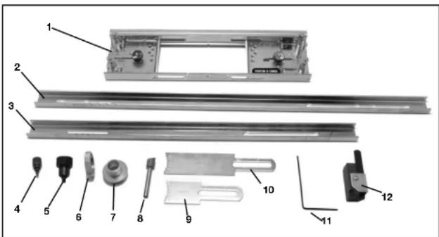
text_image
Exploded view diagram of a mechanical assembly with numbered parts for identificationThe standard parts for the 59381 Hinge Butt Template include:
Templates (4)
-
Long rails (2)
-
Short rails (3)
-
Thumb screws, small (8)
-
Thumb screws, large (6)
-
Locknut (42237)
-
5/8" OD Template guide (42042)
-
Carbide-tipped bit with 1/2" diameter cutter (43437PC)
-
Short end gauge (2) for 5" and 6"
-
Long end gauge (2) for 7" and 8"
-
Hex key
-
Corner chisel
HINGE CORNER RADIUS
The hinge corner radius is determined by certain combinations of template guide and router bits. The following two hinge corner radius styles can be created using the parts that come standard:
For hinges with 1/4" radius corners:
•Template guide with 5/8* OD (42042)
-Router bit with 1/2" diameter cutter (43437PC - carbide tipped)
For hinges with square corners:
- Use the bits and guides for 1/4^ radius corners
- Use the included corner chisel to make the corners square
For other hinge corner radius styles, consult the list below for additional bits and template guides that are needed:
For hinges with 5/16" radius corners:
- Template guide with 59/64" OD (42039)
- Router bit with 5/8" diameter cutter (43440PC)
For hinges with 5/8" radius corners:
- Template guide with 1-35/64" OD (42048)
- Router bit with 1-1/4" diameter cutter (43442PC)
NOTE: The part numbers in parenthesis are Porter-Cable part numbers.
JAMB GAUGES
Jamb Gauges (not included) are required to set up the template to route wood doors to fit into pre-routed wood or metal jambs or to provide clearance for weather stripping. Jamb gauges are available through a Porter-Cable service center. Recessed slots are provided in the kitbox for jamb gauge storage.
GETTING PREPARED
WHEN HANGING DOORS 6 TO 7 FEET TALL: Clearance at top of door may be 1/16" or 1/8". The top of the top hinge may be located anywhere between 5" to 6" from the top of the door. The bottom of the bottom hinge may be located anywhere from 9" to 10" from the floor. Use short end gauge marked with 5" and 6".
text_image
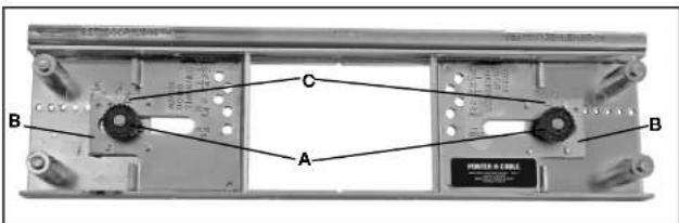
B C A B POWER & CABLEFig. 1
text_image
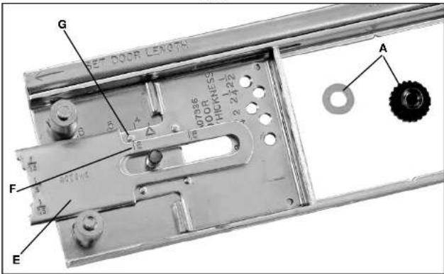
SET DOOR LENGTH G F E A 1/2 1/3 1/2 1/3 1/2 1/3 1/2 1/3 1/2 1/3 1/2 1/3 1/2 1/3 1/2 1/3 1/2 1/3 1/2 1/3 1/2 1/3 1/2 1/3 1/2 1/3 1/4 1/3 1/4 1/3 1/4 1/3 1/4 1/3 1/4 1/3 1/4 1/3 1/4 1/3 1/4 1/3 1/4 1/3 1/4 1/3 1/4 1/3 1/4 1/3 1/4 1/2 1/4 1/2 1/4 1/2 1/4 1/2 1/4 1/2 1/4 1/2 1/4 1/2 1/4 1/2 1/4 1/2 1/4 1/2 1/4 1/2 1/4 1/2 1/4 1/2 1/5 1/2 1/5 1/2 1/5 1/2 1/5 1/2 1/5 1/2 1/5 1/2 1/5 1/2 1/5 1/2 1/5 1/2 1/5 1/2 1/5 1/2 1/5 1/2 1/5 1/3 1/5 1/3 1/5 1/3 1/5 1/3 1/5 1/3 1/5 1/3 1/5 1/3 1/5 1/3 1/5 1/3 1/5 1/3 1/5 1/3 1/5 1/3 1/5 1/3 1/6 1/2 1/6 1/2 1/6 1/2 1/6 1/2 1/6 1/2 1/6 1/2 1/6 1/2 1/6 1/2 1/6 1/2 1/6 1/2 1/6 1/2 1 /4 0.0000000000000000000000000000000000000000000000000000000000000000000000000000000000000000000000000000Fig. 2
text_image
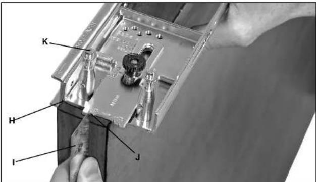
K H I JFig. 3
WHEN HANGING DOORS 7 TO 8 FEET TALL: The top of the top hinge may be located anywhere between 7" to 8" from the top of the door. The bottom of the bottom hinge may be located anywhere from 10" to 11" from the floor. Use long end gauge marked with 7" and 8".
DETERMINING HANDING OF DOOR
Either left or right hand doors may be routed. There are several ways to determine the handing of a door. For our purposes, we use the visible hinge method. To determine a left-hand door or a right-hand door, face the door opening from the side on which the hinge pins will be visible after door is hung. If hinge pins are on the right, it is a right-hand door. If pins are to the left, it is a left-hand door.
POSITIONING DOOR FOR ROUTING
While facing the door from the side on which the hinge pins will be visible, set the right-hand door on a long edge with the top of the door to the left. Set a left-hand door on an edge with the top to the right. The hinge areas to be routed will face up. Secure door in this position by clamping to a sturdy worktable or bench.
▲WARNING: Laceration hazard. Do not attempt to use the router on an unsupported workpiece.
TEMPLATES, RAILS AND THUMB SCREWS NEEDED
FOR THREE HINGE DOOR: Three templates, two long rails (Part No. A07338), four large thumb screws and six small thumb screws (if there is no stop in the door jamb area).
FOR FOUR HINGE DOOR: Four templates, three short rails (Part No. A16852), six large thumb screws and eight small thumb screws (if there is no stop in the door jamb area).
ASSEMBLING TEMPLATE FOR RIGHT-HAND DOOR
For this section, we will describe how to set up the Hinge Butt Template for a specific situation. For the example, we will explain how to mortise three hinges for a 1-3/8" thick, 6'8" right-hand door with 3½" long hinges that start 5" down from the top of the door. Our clearance between top of door and jamb is 1/16".
NOTE: Change the measurements below to fit any specific situation.
-
On each template section, loosen thumb nuts (A) Fig. 1 and adjust hinge size plates (B) so the triangle indicators (C) align with the 312 marks on the template body. Adjust all template sections in the same manner. Be sure pin on bottom of hinge size plate engages hole in template body. Tighten thumb nuts (A) securely.
-
With left template section oriented as shown in Fig. 2, remove the left thumb nut and washer (A) and install the 5" (or short) end gauge (E) as shown. Align the scribed line (F) next to the number "5" with center of alignment pin (G). Use the end gauge that corresponds with where the top of the hinge should be placed.
-
Set the left template section on the top edge of the door on the left and snug template edge (H) Fig. 3 against door. Place straight edge (I) on left edge (top) of door and slide the template over until the end gauge 1/16" step (J) is against straight edge (I). Drive nails (K) into door.
-
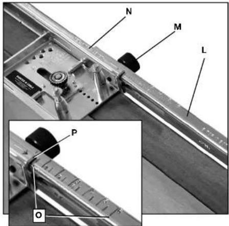
Attach the rail (L) Fig. 4 with rail adjusting thumb screw (M) to right end of the template section (N) which has been nailed to door. Before tightening screw (M), adjust rail (L) so the 3 12 " graduation line on the "5 TOP 10 BOTTOM" scale (as shown at (O), Fig. 4 insel), lines up with the end (P) of template section (N).
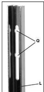
NOTE: There are recesses (Q) Fig. 5 in the rail (L) for the 3½" hinge size. When sizing for 3½" hinges, be sure the plunger in the thumb screw (M) Fig. 4 locates in the recess to help prevent movement.
NOTE: When the hinge size is something other than 3½", the plunger within thumb screw (M) retracts. Care should be taken not to jar adjusting channel out of location.
NOTE: Use the scale for "7 TOP 11 BOTTOM" to locate the 3-1/2" mark (as described in Step 4) if using the long end gauge.
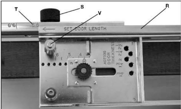
- Line up the center template section (R) Fig. 7 so the end of the template lines up with the 6'8" mark (T) on the rail that was just installed. Attach the template at this location using a rail adjustment thumb screw (S).
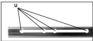
NOTE: Recesses (U) Fig. 6 in the rails are provided for 6', 6'6', 6'8" and 7' doors. Tighten screw (S) Fig. 7, being sure the plunger within the screw locates in the recess to help prevent movement.
NOTE: When mortising other size doors, the plunger within thumb screw (S) retracts. Care should be taken not to jar adjusting channel out of adjustment.
-
Snug template edge against door and drive nails (M) into door.
-
Attach the next rail to right end of center template section as outlined in Step 4.
NOTE: When hanging a four-hinge door, two center templates will result, as shown in Fig. 9.
- Attach the right (final) template section to the door as outlined in Step 5. The door is now ready for routing the hinge areas. (Final template sections should look like Fig. 9.)
ASSEMBLING TEMPLATE FOR LEFT-HAND DOOR
Here are the differences for setting up the template to route a left-hand door:
-
Assemble template as outlined for right-hand doors but DO NOT DRIVE NAILS and DO NOT INSTALL THE END GAUGE.
-
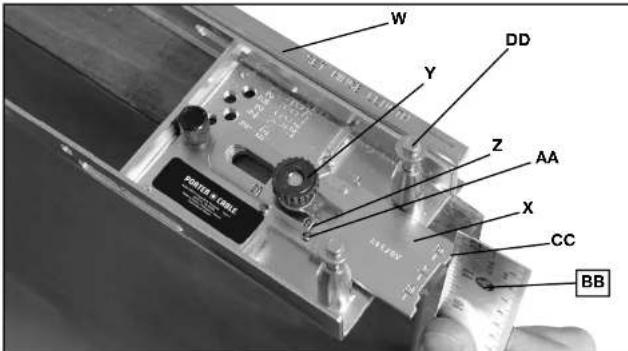
Facing door, set the assembled Hinge Butt Template on edge of door. In the right template section (W) Fig. 8, attach the 5" (or short) end gauge (X) underneath the right side thumb nut and washer (Y). Line up the end gauge (X) so the scribed line (Z) next to the number 5 is in the center of alignment pin (AA).
-
Place a straight edge (BB) against the top (right end) of the door. Move template so that the 1/16" step (CC) in the end gauge (X) is touching the straight edge and nail the template in place.
text_image
N M L P OFig. 4
text_image
a LFig. 5
natural_image
Diagram showing a ray labeled 'U' projecting onto a surface with multiple parallel lines (no text or symbols)Fig. 6
text_image
T S V 6'6 5'91 SET DOOR LENGTH R A07336 DOOR THICKNESS 13 2 4 22 18 14 2 2 4 22Fig. 7
text_image
W Y DD Z AA X CC BBFig. 8
SELECTING ROUTER BIT
Determine the size of the corner radius on hinges to be installed and select corresponding bit and template guide. (See "HINGE CORNER RADIUS" section for guidance.)
To insure correct size mortise is cut it is important that only the template guide specified for the size of bit selected be used. If hinges have square corners, the 1/4" diameter bit and corresponding template guide are recommended. A corner chisel, to square the corners of cut mortise, is included for this task.
PREPARING ROUTER
⚠ WARNING: Read and follow the instructions in your router's owner's manual.
⚠ WARNING: To reduce the risk of injury, turn router off and disconnect it from power source before installing and removing accessories, before adjusting or when making repairs. An accidental start-up can cause injury.
-
Assemble template guide to router base with lock nut and tighten lock nut securely.
-
Install selected bit in router collet and tighten securely.
-
Set router on Hinge Butt Template and adjust depth of cut so bit just touches door.
-
Set router depth adjusting ring to zero position.
-
Lift router from template and adjust depth of cut equal to thickness of hinge to be installed.
-
Firmly tighten motor locking device.
DOOR HINGE ROUTING
⚠ WARNING: Before making any cuts, be sure to read the router owner's manual for safe operating instructions.
-
Connect cord to power source.
-
Secure door by clamping to a sturdy worktable or bench.
▲WARNING: Laceration hazard. Do not attempt to use the router on an unsupported workpiece.
-
Start motor and place router on template and make first cut from right to left along outer edge of door.
-
Rout out remainder of mortise by moving router from left to right.
-
When mortise has been completely cut, turn off router and wait for the motor to come to a complete stop before moving the router.
-
Rout remaining mortises in the same manner.
REMOVING TEMPLATE FROM DOOR
Pull the nails securing template to door by inserting the claw end of a claw hammer under nail heads, one of which is shown at (DD) Fig. 8.
ROUTING JAMB WITH DOOR STOPS ALREADY IN PLACE
-
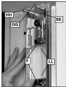
Place assembled Hinge Butt Template up against door jamb so the end gauge (EE) Fig. 10 is now touching the top of door jamb (GG) as shown.
-
Hold template snug against the door stop (FF) Fig. 10 and up against the top jamb (GG) and drive in nails, one of which is shown at (HH). To finish hanging the template, hold each remaining section snug against door stop and drive in nails (not shown).
-
Rout mortise in same manner as for door.
ROUTING JAMBS WITHOUT DOOR STOP IN PLACE
- Screw in two jamb stop pins (II) Fig. 11, in each template section in the correct holes (JJ) Fig. 12
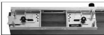
TEMPLATE SET UP FOR THREE-HINGE RIGHT-HAND DOOR/ GABARIT INSTALLÉ POUR UNE PORTE À OUVERTURE À DROITE ET À TROIS CHARNIÈRES CONFIGURACIÓN DE LA PLANTILLA PARA UNA PUERTA A DERECHAS DE TRES BISAGRAS.
natural_image
Exterior view of a mechanical device with control panels and buttons (no visible text or symbols)LEFT TEMPLATE SECTION SECTION GAUCHE DU GABARIT SECCIÓN IZQUIERDA DE LA PLANTILLA:
natural_image
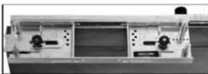
Mechanical assembly with two transparent components and mounting holes (no visible text or symbols)RIGHT TEMPLATE SECTION SECTION DROITE DU GABARIT SECCIÓN DERECHA DE LA PLANTILLA
TEMPLATE SET UP FOR FOUR-HINGE RIGHT-HAND DOOR / GABARIT INSTALLÉ POUR UNE PORTE À OUVERTURE À DROITE ET À QUATRE CHARNIÈRES / CONFIGURACIÓN DE LA PLANTILLA PARA UNA PUERTA A DERECHAS DE CUATRO BISAGRAS.
LEFT TEMPLATE SECTION
SECTION GAUCHE DU GABARIT
SECCIÓN IZQUIERDA DE LA PLANTILLA:
text_image
HH GG FF EEFig. 10
text_image
HH GG EE II LLFig. 11
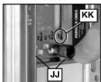
Fig. 12
for the thickness of the door being hung. In the case of the example being used, the pins would be installed in the holes marked 1 3/8" (KK).
- Place assembled Hinge Butt Template against jamb so the end gauge (EE) Fig. 11 is against top of door jamb (GG).
- Starting with the top template section hold pins (II) Fig. 11, against front edge of door jamb (LL) and drive nails, one of which is shown at (HH). Repeat for other sections.
- Rout mortise in same manner as for door.
SETTING TEMPLATE FOR FITTING WOOD DOORS
TO METAL JAMBS OR PREVIOUSLY MORTISED WOOD JAMBS
NOTE: Jamb gauges are available as service parts through Porter-Cable. See *JAMB GAUGES* section for guidance.
- Assemble complete Hinge Butt Template as outlined previously, but do not nail to door.
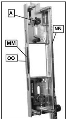
NOTE: Be sure to first read through the instructions below and then guide the assembly to fit the specific hinge size. - Select correct jamb gauge (MM) Fig. 13 for size of hinge to be used and assemble to each template section (NN) using provided screws (OO). Be sure to align the pin (not shown) on the back of the jamb gauge into the matching hole in the template before tightening screws.
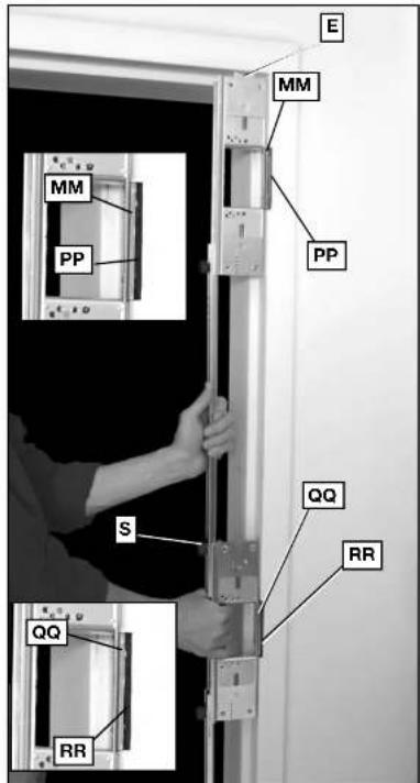
- Lift assembled Hinge Butt Template Fig. 14 into the jamb and fit the jamb gauge (MM), into the previous mortise (PP) for the top hinge.
- Loosen thumb nut (A) Fig. 13, and adjust end gauge (E) Fig. 14, until it touches the top of the door jamb. Tighten thumb nut securely.
- Keeping top template section jamb gauge mated with previous mortise, loosen rail adjustment thumb screw (S) Fig. 14, and adjust center template section so that the jamb gauge (QQ) mates with previous mortise (RR). Tighten thumb screw (S) securely.
- Keeping jamb gauges mated with mortises (PP) and (RR), adjust remaining rails and template sections in the same manner.
- Transfer complete adjusted template to door, being careful not to jar it out of adjustment. Align the end gauge to the top of the door as shown in Fig. 3. Use a straight edge (I) to align the appropriate step (J) - either 1/16" or 1/8" - to the door. Drive nails into door keeping template edge (H) Fig. 3 snug against door.
- Route door as outlined under ROUTING DOOR FOR HINGES.
MAKING ALLOWANCE FOR WEATHER-STRIPPING
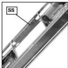
On exterior door jamb with door stops already in place, allowance can be made for weather-stripping by attaching correct size jamb gauge for hinge being installed to the inside of each template section (SS) Fig. 15, before mortising the jamb. These gauges are not required when mortising the door.
TROUBLESHOOTING
For assistance with your tool, visit our website at www.porter-cable.com for a list of service centers, or call the Porter-Cable Customer Care Center at (888) 848-5175.
MAINTENANCE
Keep template clean, remove accumulation of chips and dust resulting from working with green or sappy woods. Replace or straighten bent rails and nails immediately. Occasionally inspect end gauge screws and side rail thumb screws to assure plungers and pins retract freely.
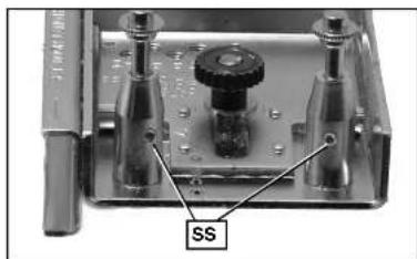
REPLACEMENT NAILS
If a template nail needs to be replaced, use the provided hex key to loosen set screw (SS) Fig. 16 at base of nail housing. When replacing the nail, do not tighten the set screw down completely. Replacement nails are available as a service part through Porter-Cable.
SERVICE
REPLACEMENT PARTS
Use only identical replacement parts. For a parts list or to order parts, visit our website at servicenet. porter-cable.com. You can also order parts from your nearest Porter-Cable Factory Service Center or Porter-Cable Authorized Warranty Service Center. Or, you can call our Customer Care Center at (888) 848-5175.
SERVICE AND REPAIRS
All quality tools will eventually require servicing and/or replacement of parts. For information about Porter-Cable, its factory service centers or authorized warranty service centers, visit our website at www.porter-cable.com or call our Customer Care Center at (888) 848-5175. All repairs made by our service centers are fully guaranteed against defective material and workmanship. We cannot guarantee repairs made or attempted by others.
You can also write to us for information at PORTER-CABLE, 4825 Highway 45 North, Jackson, Tennes-
text_image
A MM OO NNFig. 13
text_image
E MM PP S QQ RR RR PP MM EFig. 14
text_image
SSFig. 15
natural_image
Close-up of a mechanical testing setup with labeled component 'SS' (no readable text or symbols beyond label)Fig. 16
see 38305 - Attention: Product Service. Be sure to include all of the information shown on the nameplate of your tool (model number, type, serial number, etc.).
ACCESSORIES
A complete line of accessories is available from your Porter-Cable Factory Service Center or a Porter-Cable Authorized Warranty Service Center. Please visit our Web Site www.porter-cable.com for a catalog or for the name of your nearest supplier.
⚠ WARNING: Since accessories other than those offered by Porter-Cable have not been tested with this product, use of such accessories could be hazardous. For safest operation, only Porter-Cable recommended accessories should be used with this product.
WARRANTY
To register your tool for warranty service visit our website at www.porter-cable.com.
PORTER-CABLE LIMITED ONE YEAR WARRANTY: Porter-Cable warrants its Professional Power Tools for a period of one year from the date of original purchase. We will repair or replace at our option, any part or parts of the product and accessories covered under this warranty which, after examination, proves to be defective in workmanship or material during the warranty period. For repair or replacement return the complete tool or accessory, transportation prepaid, to your nearest Porter-Cable Factory Service Center or Porter-Cable Authorized Warranty Service Center. Proof of purchase may be required. This warranty does not apply to repair or replacement required due to misuse, abuse, normal wear and tear or repairs attempted or made by other than our serviceCenters or authorized warranty service centers.
ANY IMPLIED WARRANTY, INCLUDING THE IMPLIED WARRANTIES OF MERCHANTABILITY AND FITNESS FOR A PARTICULAR PURPOSE. WILL LAST ONLY FOR ONE (1) YEAR FROM THE DATE OF PURCHASE. To obtain information on warranty performance please write to: PORTER-CABLE, 4825 Highway 45 North, Jackson, Tennessee 38305; Attention: Product Service. THE FOREGOING OBLIGATION IS PORTERCABLE'S SOLE LIABILITY UNDER THIS OR ANY IMPLIED WARRANTY AND UNDER NO CIRCUMSTANCES SHALL PORTER-CABLE BE LIABLE FOR ANY INCIDENTAL OR CONSEQUENTIAL DAMAGES. Some states do not allow limitations on how long an implied warranty lasts or the exclusion or limitation of incidental or consequential damages, so the above limitation or exclusion may not apply to you.
This warranty gives you specific legal rights and you may also have other legal rights which vary from state to state.
MESURES DE SÉCURITÉ - DÉFINITIONS
text_image
Exploded view diagram of a mechanical assembly with numbered parts for identificationtext_image
Exploded view diagram of a mechanical assembly with numbered parts for identificationlong-in expert consultation
4825 Highway 45 North
Jackson, TN 38305
(888) 848-5175
www.porter-cable.com