
273233 - Laser level SILVERLINE - Free user manual and instructions
Find the device manual for free 273233 SILVERLINE in PDF.

| Product Type | Rotary Laser Level |
| Brand | Silverline |
| Model | 273233 |
| Voltage | 6 V DC |
| Power | 200-300 mA |
| Battery Type | 4 C-type batteries (1.5 V each) |
| Laser Class | Class II |
| Laser Wavelength | 650 nm |
| Laser Line Range | 10 m max |
| Accuracy | 0.5 mm/m |
| Tripod Height | 540 - 1180 mm |
| Dimensions on Feet (L x W x H) | 720 x 600 x 1180 mm |
| Protection Rating | IP20 |
| Weight | 1.6 kg |
| Warranty | 3 years (upon registration within 30 days) |
| Main Functions | Horizontal and vertical leveling, plumb line, horizontal and vertical rotation |
| Included Accessories | Carrying case, tripod, adjustment screwdriver |
| Maintenance | Clean with a soft, damp cloth; do not use caustic products |
| Safety | Class II laser, do not look directly into the beam, wear protective glasses |
| Repairability | Repair by a qualified technician using identical spare parts |
Frequently Asked Questions - 273233 SILVERLINE
User questions about 273233 SILVERLINE
0 question about this device. Answer the ones you know or ask your own.
Ask a new question about this device
Download the instructions for your Laser level in PDF format for free! Find your manual 273233 - SILVERLINE and take your electronic device back in hand. On this page are published all the documents necessary for the use of your device. 273233 by SILVERLINE.
USER MANUAL 273233 SILVERLINE
Rotary Laser Level Kit 30m Range
natural_image
Exterior view of a tripod-mounted surveying instrument with black and white components (no text or symbols visible)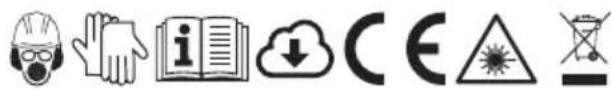
silverlinetools.com
English ......04
Français ......08
Deutsch......12
Español......16
Italiano ......20
Nederlands ......24
Polski ......28
Introduction
Thank you for purchasing this Silverline tool. This manual contains information necessary for safe and effective operation of this product. This product has unique features and, even if you are familiar with similar products, it is necessary to read this manual carefully to ensure you fully understand the instructions. Ensure all users of the tool read and fully understand this manual.
Description of Symbols
The rating plate on your tool may show symbols. These represent important information about the product or instructions on its use.

Wear hearing protection
Wear eye protection
Wear breathing protection
Wear head protection

Wear hand protection

Read instruction manual

Conforms to relevant legislation and safety standards.

LASER warning!

Environmental Protection
Waste electrical products should not be disposed of with household waste.
Please recycle where facilities exist. Check with your local authority or retailer for recycling advice.
Specification
Input voltage: 6V, DC
Power: 200-300mA
Battery type: 4 x C-cell batteries, 1.5V
Laser class: Class II
Laser wavelength: 650nm
Laser output power .... <1mW
Laser working range:
Laser line: Max 10m
Laser dot: Max 30m
Accuracy: 0.5mm/m
Tripod height: 540-1180mm
Standing dimensions (WxLxH): 720 x 600 x 1180mm
Ingress protection: IP20
Weight: 1.6kg
As part of our ongoing product development, specifications of Silverline products may alter without notice.
General Safety
WARNING Read all safety warnings and all instructions. Failure to follow the warnings and instructions may result in electric shock, fire and/or serious injury.
WARNING: This device is not intended for use by persons (including children) with reduced, physical or mental capabilities or lack of experience or knowledge unless they have been given supervision or instruction concerning use of the device by a person responsible for their safety. Children must be supervised to ensure that they do not play with the device.
Save all warnings and instructions for future reference.
Work area safety
a) Do not operate electrical devices in explosive atmospheres, such as in the presence of flammable liquids, gases or dust. Electrical devices create sparks which may ignite the dust or fumes.
Electrical safety
a) Electrical plugs must match the outlet. Never modify the plug in any way. Do not use any adapter plugs with earthed (grounded) devices. Unmodified plugs and matching outlets will reduce risk of electric shock.
b) Avoid body contact with earthed or grounded surfaces, such as pipes, radiators, ranges and refrigerators. There is an increased risk of electric shock if your body is earthed or grounded.
c) Do not expose non-waterproof electrical devices to rain or wet conditions. Do not submerge non-pressure-rated devices in water. Water entering an electrical device will increase the risk of electric shock.
d) Do not abuse the power lead. Never use the lead for carrying, pulling or unplugging the device. Keep lead away from heat, oil, sharp edges or moving parts. Damaged or entangled power leads increase the risk of electric shock.
e) If operating an electrical device in a damp location is unavoidable, use a residual current device (RCD) protected supply. Use of an RCD reduces the risk of electric shock.
WARNING: When used in Australia or New Zealand, it is recommended that devices are ALWAYS supplied via Residual Current Device (RCD) with a rated residual current of 30mA or less.
Personal safety
a) Stay alert, watch what you are doing and use common sense when operating an electrical device. Do not use potentially dangerous electrical devices while you are tired or under the influence of drugs, alcohol or medication. A moment of inattention while operating potentially dangerous devices may result in serious personal injury.
b) Use personal protective equipment including eye protection where appropriate. Protective equipment used for appropriate conditions will reduce personal injuries.
c) Prevent unintentional starting. Ensure the switch is in the off-position before connecting to a power source. Carrying electrical devices with your finger on the switch or energising devices that have the switch on invites accidents.
d) Do not overreach. Keep proper footing and balance at all times. This enables better control of the device in unexpected situations.
Use and Care
a) Do not force the device. Use the correct device for your application. The correct device will do the job better and safer at the rate for which it was designed.
b) Do not use the electrical device if the switch does not turn it on and off. Any device that cannot be controlled with the switch is dangerous and must be repaired.
c) Disconnect the power source before making any adjustments, changing accessories, or storing electrical devices. Such preventive safety measures reduce the risk of starting the device accidentally.
d) Store idle devices out of the reach of children and do not allow persons unfamiliar with
the device or these instructions to operate it. Electrical devices may be dangerous in the hands of untrained users.
c) Maintain electrical devices. Check for defects of parts and any other condition that may affect the device's operation. If damaged, have the device repaired before use. Many accidents are caused by poorly maintained electrical devices.
1) Use the device and its accessories in accordance with these instructions, taking into account the conditions and the task to be performed. Use of the device for operations different from those intended could result in a hazardous situation.
Service
a) Have your electrical devices serviced by a qualified repair person using only identical replacement parts. This will ensure that the safety of the device is maintained.
Safety rules for laser lights
The laser used in this device is a Class 2 laser with maximum power of ≤1mW and a wavelength of 650nm.
These lasers do not normally present an optical hazard, although staring at the beam may cause flash blindness.
WARNING: Avoid direct eye contact.
A hazard may exist if you deliberately stare into the beam. Please observe all safety rules as follows:
- The laser shall be used and maintained in accordance with the manufacturer's instructions
- Never aim the beam at any person, and particularly not into the eyes of any person or animal, or any object other than the workpiece
- Always ensure the laser beam is aimed at a sturdy workpiece without reflective surfaces. i.e. wood or rough-coated surfaces are acceptable. Reflective sheet steel or similar is not suitable for laser use as the reflective surface could direct the beam back at the operator
- Do not change the laser light assembly. Repairs must only be carried out by the laser manufacturer or an authorised agent. DO NOT exchange with a different type of laser
CAUTION: Use of controls or adjustments or performance of procedures other than those specified herein may result in hazardous radiation exposure.
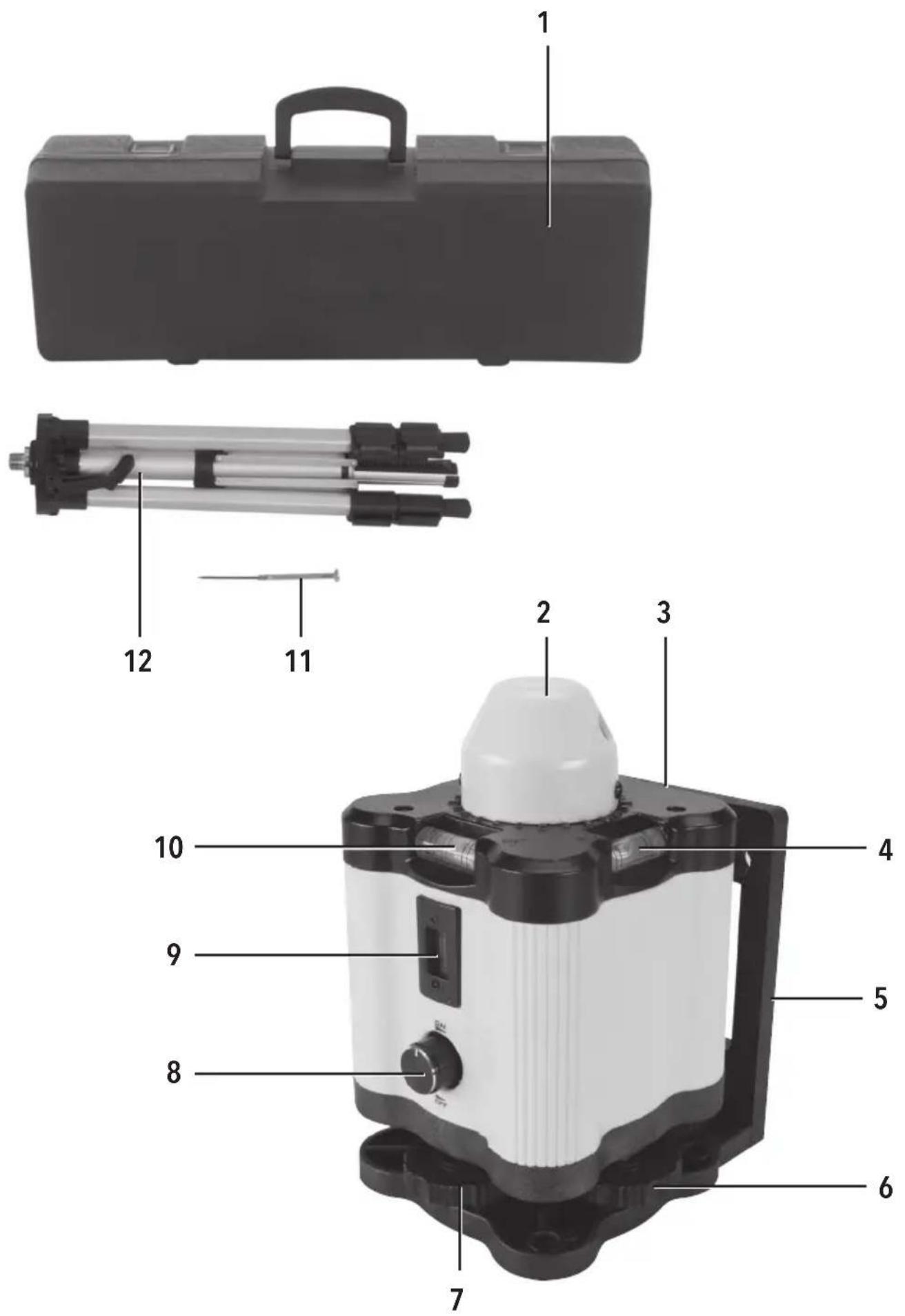
Product Familiarisation
| 1 Carry Case |
| 2 Rotary Head |
| 3 Rotary Laser Level Unit |
| 4 Y Vial |
| 5 Frame |
| 6 X Axis Levelling Screw |
| 7 Y Axis Levelling Screw |
| 8 Control Button |
| 9 Plumbers Vial |
| 10 X Vial |
| 11 Screwdriver |
| 12 Tripod |
Intended Use
Battery-powered rotating laser kit for levelling applications during building work, tiling, brick laying, timber frame construction etc.
Unpacking your Tool
- Carefully unpack and inspect your tool. Familiarise yourself with all its features and functions
- Ensure that all parts of the tool are present and in good condition. If any parts are missing or damaged, have such parts replaced before attempting to use this tool
Before Use
Inserting batteries
- Remove the cover from the battery compartment in the rear of the Rotary Laser Level Unit (3)
- Insert the batteries, making sure that the positive and negative terminals are the correct way round, as shown on the cover of the battery housing
- Replace the cover
Setting up for levelling
- Screw the Tripod (12) into the brass fitting on the Frame (5), so that the Rotary Head (2) is uppermost
Setting up for plumbing
- Screw the Tripod (12) into the alternative fitting (without brass insert) on the Frame (5), so that the Control Button (8) is uppermost
In all cases
- Use the snap-fit connectors to extend and lock the tripod legs, and the winder handle to extend the mount for the rotary laser level as needed
Calibrating the laser level
Checking horizontal rotational level:
- Position your Rotary Laser Level Unit (3) approximately 10m away from the wall ensuring that the Control Button (8) is facing the wall. Use the Levelling Screws (6 & 7) to adjust the level so that the bubble is in the centre of each vial
- Turn the power on for static laser beam, and rotate the Rotary Head (2) manually (if necessary) so that the laser beam is pointing directly ahead on the wall. Mark as point A
- Turn power off and rotate the unit 180^ so that the back of the Rotary Laser Level Unit is now facing the original wall
- Re-level the Rotary Laser Level Unit
- Turn the power on for static laser beam, then rotate the Rotary Head (2) so that the laser beam is pointing onto the original wall. Mark as point B
- Measure the vertical distance to both points A and B from the floor. No adjustments to the laser level are necessary if the vertical measurements have a difference of 3mm or less
Correcting horizontal rotational level:
- Adjust the X Axis Levelling Screw (6) (adjacent to the X Vial) so the laser beam shows midway between points A and B. This will cause the bubble in the X Vial (10) to shift from the centre.
- Centre the X vial bubble by adjusting the X Axis Levelling Screw with Screwdriver (11) supplied
- Re-check the accuracy of the laser by repeating the calibration process as necessary
Checking vertical rotational level:
- Position the unit on its tripod on the floor approximately 15m from the base of the wall. The right side of the unit should face the wall. Level the unit by adjusting the Y Axis Levelling Screw (7)
- Mark a point A on the lower part of the wall. Turn the power on and manually direct the laser beam to point A
- Turn the Rotary Head (2) so the laser beam moves approximately 4.5m upwards on the wall. Mark as point B
- Rotate the Rotary Laser Level Unit (3) by 180° so the left side of the unit faces the wall. Re-level the unit by adjusting the Y Axis Levelling Screw. Manually direct the laser beam to point A
- Turn the Rotary Head so that the laser beam is at the same height as point B. Mark as point C. No adjustments are necessary if the difference between points B and C is 2mm or less
Correcting vertical rotational level:
- Adjust the Y Axis Levelling Screw (7) (adjacent to the vial) so laser beam is midway between points B and C. This will cause the bubble in the Y Vial (4) to shift from the centre
- Centre the Y vial bubble by adjusting the Y Axis Levelling Screw with Screwdriver (11) supplied
- Re-check the accuracy of the laser by repeating the calibration process as necessary
Alternative calibration method
- Using a spirit level, mark a straight horizontal line on the wall at the height required for your project
Checking the X-axis vial:
- Position the Rotary Laser Level Unit approximately 10m away from the wall, ensuring that the X Vial (10) is facing the wall
- Turn the power on so that the Rotary Head (2) spins to create a line on the wall
- Adjust the X Axis Levelling Screw (6) until the laser line matches the line you have drawn on the wall
- If the bubble is not in the centre of the X Vial (10), use the Screwdriver (11) supplied to adjust the vial until the bubble is centred
Checking the Y-axis vial:
- Turn the unit through 90° so that the Y Vial (4) is facing the wall
- Repeat procedure as above, adjusting the Y Axis Levelling Screw (7)
Operation
Levelling
- Set up your rotary laser level in accordance with guidance in 'Before Use' section
- Ensure that the rotary laser is level by checking the vials and adjusting the levelling screws. See 'Calibrating the Laser Level' for guidance
- Turn power on and use the control button to establish the correct speed
• Mark the desired positions
Plumbing
- Set up your rotary laser level in accordance with guidance in 'Setting Up' section
- Ensure that the rotary laser is level by adjusting the Y Axis Levelling Screw (6) until the bubble is centred
- Turn power on and use the Control Button (8) to establish the correct speed
• Mark the desired positions - It is also possible to operate the unit manually: switch on the unit and turn the unit by hand until the laser beam is aligned with your target
Accessories
- A full range building accessories is available from your Silverline stockist
Maintenance
Cleaning
WARNING: ALWAYS wear protective equipment including eye protection and gloves when cleaning this tool.
- Keep your tool clean at all times. Dirt and dust will cause internal parts to wear quickly, and shorten the device's service life
- Clean the body of your machine with a soft brush, or dry cloth
- Never use caustic agents to clean plastic parts. If dry cleaning is not sufficient, a mild detergent on a damp cloth is recommended
• Water must never come into contact with the tool - Ensure the tool is thoroughly dry before using it
- If available, use clean, dry, compressed air to blow through the ventilation holes (where applicable)
Storage
- Store this tool carefully in a secure, dry place out of the reach of children
Disposal
Always adhere to national regulations when disposing of power tools that are no longer functional and are not viable for repair.
- Do not dispose of power tools, batteries or other waste electrical and electronic equipment (WEEE), with household waste
- Contact your local waste disposal authority for information on the correct way to dispose of power tools
Silverline Tools Guarantee
This Silverline product comes with a 3 year guarantee
Register this product at www.silverlinetools.com within 30 days of purchase in order to qualify for the 3 year guarantee. Guarantee period begins according to the date of purchase on your sales receipt.
Registering your purchase
Registration is made at silverlinetools.com by selecting the Guarantee Registration button. You will need to enter:-
- Your personal details
• Details of the product and purchase information
Once this information is entered your guarantee certificate will be created in PDF format for you to print out and keep with your purchase.
Terms & Conditions
Guarantee period becomes effective from the date of retail purchase as detailed on your sales receipt.
PLEASE KEEP YOUR SALES RECEIPT
If this product develops a fault within 30 days of purchase, return it to the stockist where it was purchased, with your receipt, stating details of the fault. You will receive a replacement or refund.
If this product develops a fault after the 30 day period, return it to:
Silverline Tools Service Centre
PO Box 2988
Yeovil
BA21 1WU, UK
The guarantee claim must be submitted during the guarantee period.
You must provide the original sales receipt indicating the purchase date, your name, address and place of purchase before any work can be carried out.
You must provide precise details of the fault requiring correction.
Claims made within the guarantee period will be verified by Silverline Tools to establish if the deficiencies are related to material or manufacturing of the product.
Carriage will not be refunded. Items for return must be in a suitably clean and safe state for repair, and should be packaged carefully to prevent damage or injury during transportation. We may reject unsuitable or unsafe deliveries.
All work will be carried out by Silverline Tools or its authorized repair agents.
The repair or replacement of the product will not extend the period of guarantee
Defects recognised by us as being covered by the guarantee shall be corrected by means of repair of the tool, free of charge (excluding carriage charges) or by replacement with a tool in perfect working order.
Retained tools, or parts, for which a replacement has been issued, will become the property of Silverline Tools.
The repair or replacement of your product under guarantee provides benefits which are additional to and do not affect your statutory rights as a consumer.
What is covered:
The repair of the product, if it can be verified to the satisfaction of Silverline Tools that the deficiencies were due to faulty materials or workmanship within the guarantee period.
If any part is no longer available or out of manufacture, Silverline Tools will replace it with a functional replacement part.
Use of this product in the EU.
What is not covered:
Silverline Tools does not guarantee repairs required as a result of:
Normal wear and tear caused by use in accordance with the operating instructions eg blades, brushes, belts, bulbs, batteries etc.
The replacement of any provided accessories drill bits, blades, sanding sheets, cutting discs and other related items.
Accidental damage, faults caused by negligent use or care, misuse, neglect, careless operation or handling of the product.
Use of the product for anything other than normal domestic purposes.
Change or modification of the product in any way.
Use of parts and accessories which are not genuine Silverline Tools components.
Faulty installation (except installed by Silverline Tools).
Repairs or alterations carried out by parties other than Silverline Tools or its authorized repair agents.
Claims other than the right to correction of faults on the tool named in these guarantee conditions are not covered by the guarantee.
Introduction
Point laser: 30 m max
Silverline Tools Service Centre
PO Box 2988
Yeovil
Linea laser: max. 10 m
Punto laser: max. 30 m
Silverline Tools Service Centre
PO Box 2988
Yeovil
BA21 1WU, GB
WAARSCHUWING: Voorkom direct oogcontact
Silverline Tools Service Centre
PO Box 2988
Yeovil
BA21 1WU, GB
Silverline Tools Service Centre
PO Box 2988
Yeovil
BA21 1WU, UK
natural_image
Exterior view of a tripod-mounted surveying instrument with a white top and black base (no text or symbols visible)GB 3 Year Guarantee. Register online within 30 days. Terms and Conditions apply.