USER MANUAL 4216 Porter-Cable
IMPORTANT SAFETY INSTRUCTIONS 3
ADDITIONAL SPECIFIC SAFETY RULES 4
Dovetail and Box Joint Overview 5.
Product Capabilities 6
4200 Series Dovetail Jig Overview 7......
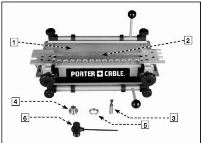
Carton Contents 7
Assembly 8
Additional Tools Required 8
Mounting Instructions 8
OPERATION
Clamps 9
Template Mounting 9
Template Support 10
Positioning the Wood 10
Half-Pins Vs. Half-Tails 1.1
Tearout Reduction 11
Aligning the Templates 11
Template Guides 12
Router Bit Depth 12
WOOD PREPARATION
Grain Direction 13
Board Thickness 13
Optimal Board Widths 13
Board Lengths 13
Project Layout 14
Drawers 14
BASIC JOINTS
Through Dovetails 15
Cutting the Tails 15
Cutting the Pins 16
Fitting and Troubleshooting 17
Half-Blind Dovetails 17
Cutting a Half-Blind Dovetail 17
Fitting and Troubleshooting 18
Half-Blind Dovetail with a Lipped Front 19
Cutting the Tails 19
Cutting the Pins 20
Fitting and Troubleshooting 20
Box Joints 21
Cutting the First Workpiece 21
Cutting the Second Workpiece 22
Sliding Dovetails 23
Dado Board 23
Tenon Board 24
Fitting and Troubleshooting 24
MAINTENANCE 25
SERVICE 25
ACCESSORIES 25
WARRANTY 26
FRANÇAISE 27
ESPAÑOL 51
SERVICE CENTER LOCATIONS Back cover
SAFETY GUIDELINES - DEFINITIONS
This manual contains information that is important for you to know and understand. This information relates to protecting YOUR SAFE TY and PRE VENT ING EQUIP MENT PROB LEMS. To help you rec og nize this in for ma tion, we use the symbols to the left. Please read the man u al and pay at ten tion to these sections.
DANGER
WARNING
CAUTION
CAUTION
Indicates an imminently hazardous situation which, if not avoided, will result in death or serious injury.
Indicates a potentially hazardous situation which, if not avoided, could result in death or serious injury.
Indicates a potentially haz ard ous situation which, if not avoided, may result in minor or mod er ate injury.
Used without the safety alert symbol indicates potentially hazardous situation which, if not avoided, may result in property damage.
IMPORTANT SAFETY INSTRUCTIONS
WARNING
Read and understand all instructions. Failure to follow all instructions listed below may result in electric shock, fire and/or serious personal injury.

SAVE THESE INSTRUCTIONS.
⚠ WARNING There are certain applications for which this tool was designed. Porter-Cable strongly recommends that this tool NOT be modified and/or used for any application other than for which it was designed. If you have any questions relative to its application DO NOT use the tool until you have written Porter-Cable and we have advised you.
Technical Service Manager
Porter-Cable Corporation
4825 Highway 45 North
Jackson, TN 38305
-
KEEP WORK AREA CLEAN. Cluttered areas and benches invite injuries.
-
AVOID DANGEROUS ENVIRONMENT. Don't expose power tools to rain. Don't use power tools in damp or wet locations. Keep area well lit. Avoid chemical or corrosive environment. Do not use tool in presence of flammable liquids or gases.
-
GUARD AGAINST ELECTRIC SHOCK. Prevent body contact with grounded surfaces. For example: pipes, radiators, ranges, refrigerator enclosures.
-
KEEP CHILDREN AWAY. Do not let visitors contact tool or extension cord. All visitors should be kept away from work area.
-
STORE IDLE TOOLS. When not in use, tools should be stored in a secure, dry place – out of reach of children.
-
DON'T FORCE TOOL. It will do the job better and safer at the rate for which it was intended.
-
USE RIGHT TOOL. Don't force small tool or attachment to do the job of a heavy duty tool. Don't use tool for purpose not intended – for example – do not use a circular saw for cutting tree limbs or logs.
-
DRESS PROPERLY. Do not wear loose clothing or jewelry. Loose clothing, draw strings and jewelry can be caught in moving parts. Rubber gloves and non-skid footwear are recommended when working outdoors. Wear protective hair covering to contain long hair.
-
USE ANSI Z87.1 SAFETY GLASSES. Wear safety glasses or goggles while operating power tools. Also face or dust mask if operation creates dust. All persons in the area where power tools are being operated should also wear safety glasses and face or dust mask.
-
DON'T ABUSE CORD. Never carry tool by cord or yank it to disconnect from receptacle. Keep cord from heat, oil, and sharp edges. Have damaged or worn power cord and strain reliever replaced immediately. DO NOT ATTEMPT TO REPAIR POWER CORD.
-
SECURE WORK. Use clamps or a vise to hold work. It's safer than using your hand and it frees both hands to operate tool.
-
DON'T OVERREACH. Keep proper footing and balance at all times.
-
MAINTAIN TOOLS WITH CARE. Keep tools sharp and clean for better and safer performance. Follow instructions for lubricating and changing accessories. Inspect tool cords periodically and if damaged, have repaired by authorized service facility. Inspect extension cords periodically and replace if damaged. Have all worn, broken or lost parts replaced immediately. Keep handles dry, clean and free from oil and grease.
-
DISCONNECT TOOLS when not in use, before servicing, and when changing accessories such as blades, bits, cutters, etc.
-
REMOVE ADJUSTING KEYS AND WRENCHES. Form habit of checking to see that keys and adjusting wrenches are removed from the tool before turning it on.
-
AVOID UNINTENTIONAL STARTING. Do not carry a plugged-in tool with finger on switch. Be sure switch is off when plugging in. Keep hands, body and clothing clear of blades, bits, cutters, etc. when plugging in the tool.
- OUTDOOR USE EXTENSION CORDS. When tool is used outdoors, use only extension cords marked "Suitable for use with outdoor appliances – store indoors when not in use." If an extension cord is to be used outdoors it must be marked with the suffix W-A or w following the cord type designation.
- STAY ALERT. Watch what you are doing. Use common sense. Do not operate tool when you are tired or while under the influence of medication, alcohol or drugs.
- CHECK DAMAGED PARTS. Before further use of the tool, a guard or other part that is damaged should be carefully checked to determine that it will operate properly and perform its intended function. Check for alignment of moving parts, binding of moving parts, breakage of parts, mounting, and any other conditions that may affect its operation. A guard or other part that is damaged should be properly repaired or replaced by an authorized service center unless otherwise indicated elsewhere in this instruction manual. Have defective switches replaced by authorized service center. Do not use tool if switch does not turn it on and off.
- WEAR ANSI S3.19 EAR PROTECTION to safeguard against possible hearing loss.
ADDITIONAL SAFETY RULES
⚠ WARNING FAILURE TO FOLLOW THESE RULES MAY RESULT IN SERIOUS PERSONAL INJURY.
- READ AND FOLLOW ALL SAFETY INSTRUCTIONS in the instruction manual supplied with your router.
- SECURE WORK. Be sure Dovetail Fixture/Jig and work is anchored securely to prevent movement.
- BE SURE CORD SET IS FREE and will not hang up during routing operations.
- KEEP HANDS CLEAR of cutter when motor is running to prevent personal injury.
- MAINTAIN FIRM GRIP on router when starting motor to resist starting torque.
- STAY ALERT and keep cutter free, clear of all foreign objects while motor is running.
- BE SURE MOTOR HAS COMPLETELY STOPPED before removing router from Dovetail Fixture/Jig and setting Dovetail Fixture/Jig down between operations.
- NEVER REMOVE ROUTER MOTOR from router base while template guide and dovetail bit are installed. dovetail bit may not fit through hole in template guide.
- TIGHTEN TEMPLATE GUIDE LOCKNUT SECURELY.
- SOME WOOD CONTAINS PRESERVATIVES WHICH CAN BE TOXIC. Take extra care to prevent inhalation and skin contact when working with these materials. Request, and follow, any safety information available from your material supplier.
REPLACEMENT PARTS
When servicing use only identical replacement parts.
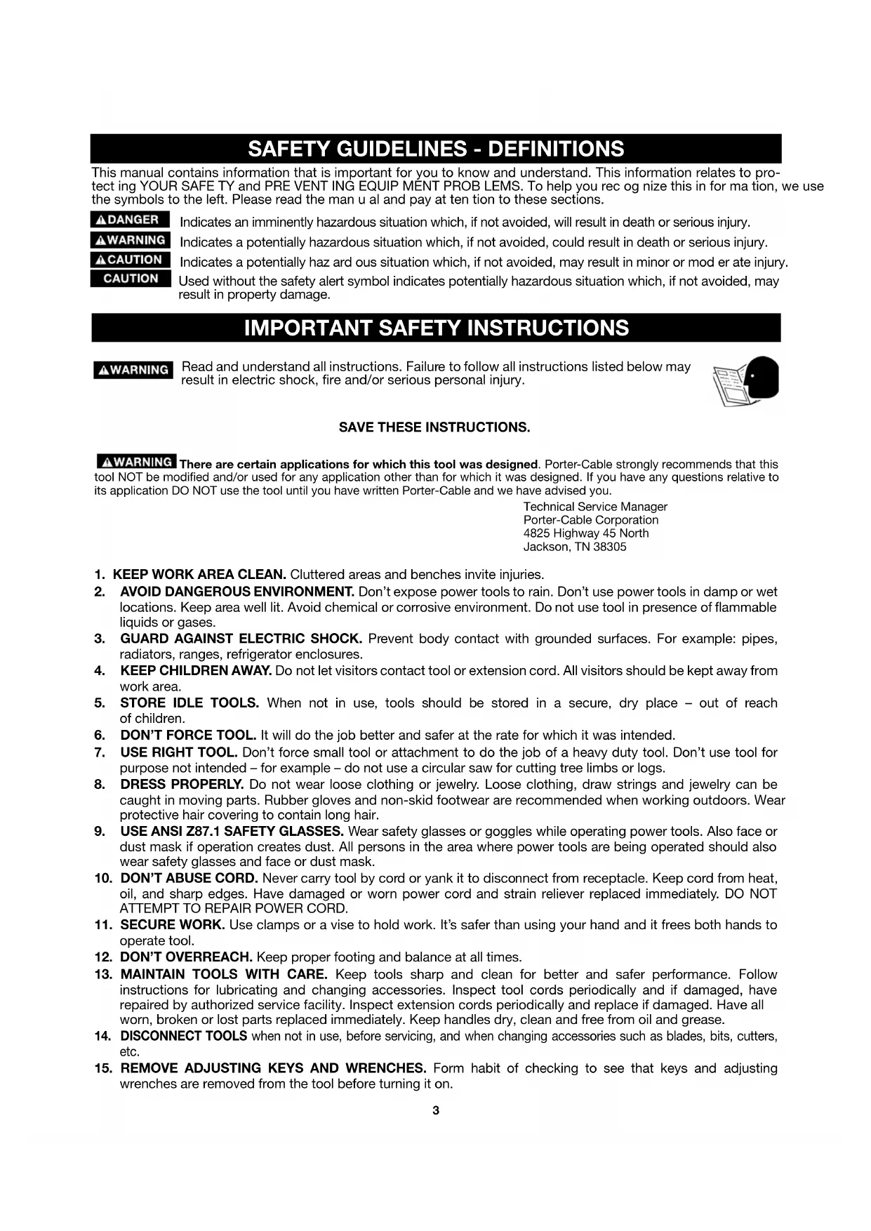
DOVETAIL AND BOX JOINT OVERVIEW
The dovetail joint is a traditional joint that is both strong and visually appealing. This joint has flared protrusions (tails) that are cut into one board (drawer side) and protrusions with slanted sides (pins) that are cut in the other board (drawer front or back). When the two pieces are joined, the tails and pins lock together mechanically, so that pulling on the drawer front will pull the drawer side as well without the need for fasteners (screws, nails, etc.). Since the pins and tails have a sufficient amount of surface, the joint is even made stronger by glue.
Types of dovetails include through dovetails, half-blind dovetails, rabbeted half-blind dovetails, mitered-through dovetails, blind dovetails, and mitered dovetails. Of these joints, the through, half-blind, and rabbeted half-blind are the most common.
NOTE: This manual includes instruction for the basic dovetail jig operations. Please visit our Web Site at www.del-taportercable.com for the supplementary manual that gives instruction for more advanced procedures.
THROUGH DOVETAILS
flowchart
graph TD
    A["Tails"] --> B["Component 1"]
    A --> C["Component 2"]
    B --> D["Component 3"]
    C --> E["Component 4"]
    D --> F["Pins"]
    E --> F
    style A fill:#f9f,stroke:#333
    style F fill:#bbf,stroke:#333
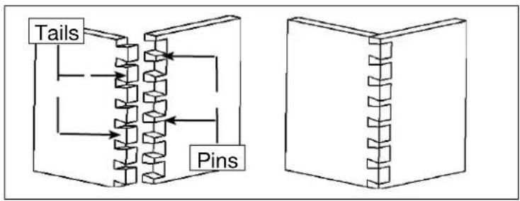
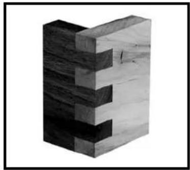
HALF-BLIND DOVETAILS
natural_image
Two 3D diagrams of rectangular blocks with serrated edges, no text or symbols present
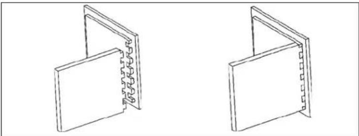
RABBETED HALF-BLIND DOVETAILS
natural_image
Two isometric line drawings of open rectangular panels with visible internal structure (no text or symbols)
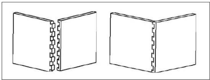
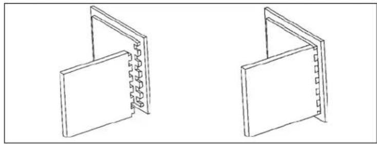
BOX (FINGER) JOINT
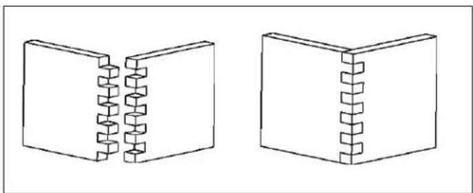
A similar joint, called a box or finger joint, has straight protrusions called fingers on both boards. This joint is used on jewelry boxes and other small boxes. The box joint is strong because it has a large surface area for glue.
natural_image
Two 3D diagrams showing a split rectangular block with internal helical grooves, no text or symbols present.
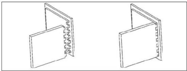
SLIDING DOVETAIL
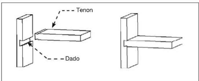
The Sliding Dovetail consists of a dovetail-shaped dado in one board and a dovetail-shaped tenon in the other board. This method is a strong way of connecting fixed shelves to walls.
text_image
Tenon
Dado
PRODUCT CAPABILITIES
The Porter-Cable 4200 series dovetail jig will help you cut these joints efficiently. An accessory kit will enable you to cut miniature versions of these joints for small gift boxes or cubbyhole drawers on a roll-top desk. The 4200 series also has the capability to cut more advanced joints (dovetails that skip pins, wood hinges, end-to-end joints, various types of angle joints, and joints with inlays).
The specific model capabilities are:
Jigs
4210 Dovetail Jig - half-blind, half-blind with a lipped front, and sliding dovetails.
4212 Deluxe Dovetail Jig - through dovetail, box joint, half-blind, half-blind with a lipped front, and sliding dovetails.
4216 Deluxe Dovetail Jig Combination Kit - through dovetail, box joint, half-blind, half-blind with a lipped front, sliding dovetails, miniature through dovetails, miniature half-blind dovetails and miniature box joints.
Accessories
4211 Accessory Kit - includes the template, router bit, and templet guide included with the model 4210.
4213 Accessory kit - incudes all items necessary to provide the 4210 jig with the same capabilities as the 4212 deluxe dovetail jig.
4215 Accessory kit - contains the template, router bits, and templet guides to make miniature through dovetails and half-blind dovetails.
JIG OVERVIEW
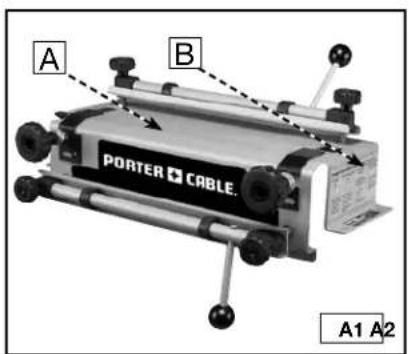
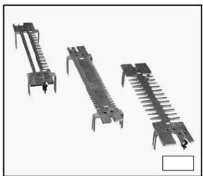
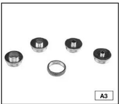
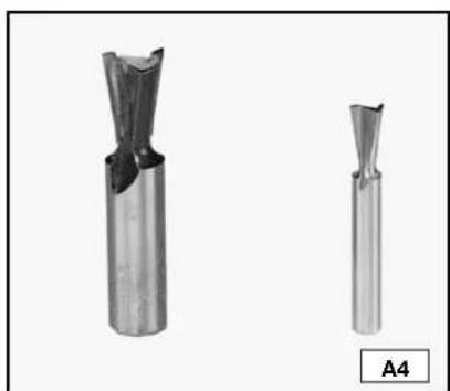
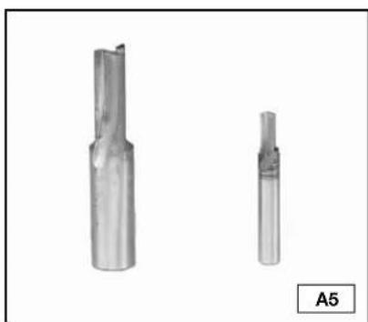
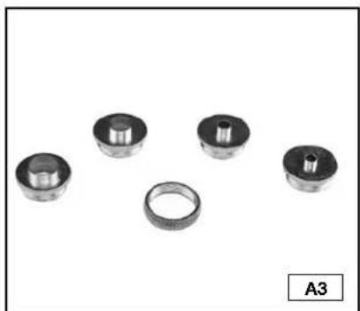
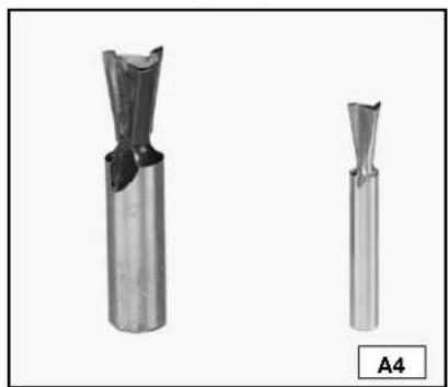
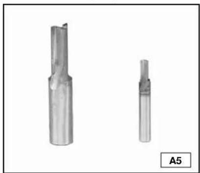
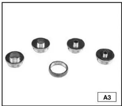
The 4200 series dovetail jigs come equipped with an easy-to-mount, heavy-duty steel base (A) Fig. A1 featuring a clamping system designed to hold wood and minimize board slippage during cuts. Troubleshooting tips (B) are provided on each side of the base. Three different machined aluminum templates (Fig. A2) can be used on the jig system to create all joints described in this manual. The fingers on each template are used in combination with the template guides (Fig. A3) to guide the router in the proper motion. Additionally, each template aids in setting proper board alignment and router bit depth. Dovetail bits and straight bits (Figs. A4 and A5) are used with this jig system.
text_image
A
B
PORTER CABLE.
A1 A2
natural_image
Three types of metal electrical connectors or tools arranged vertically (no text or symbols visible)
natural_image
Five mechanical bearing components arranged in a row, including a ring and three cylindrical bearings (no text or symbols visible)
natural_image
Two metallic cutting tool holders shown from different angles, labeled A4 (no text or symbols on the tools themselves)
natural_image
Two metallic cutting tool holders shown from different angles, labeled A5 (no text or symbols on the tools themselves)
CARTON CONTENTS
DOVETAIL JIGS
4210

text_image
PORTER CABLE.
- Base
- Half-blind & Sliding Dovetail Template
- Dovetail Bit
- Template Guide
- Lock nut
- T-handle Hex Wrench
4212
text_image
PORTER + CABLE
1
2
3
4
5
6
7
8
- Base
- Half-blind & Sliding Dovetail Template
- Through & Box Template
- Dovetail Bit
- Straight Bit
- Template Guide (2)
- Lock Nuts (2)
- T-handle Hex Wrench
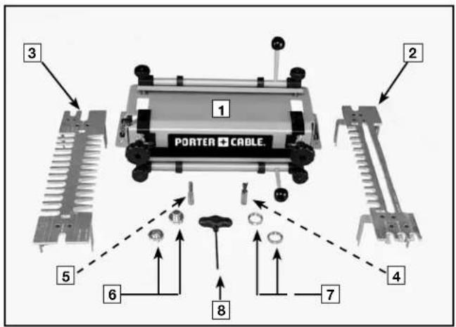
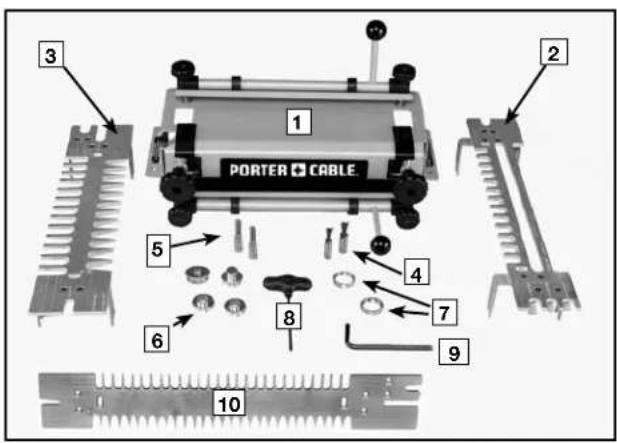
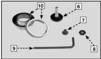
4216
text_image
PORTER CABLE
1
2
3
4
5
6
7
8
9
10
- Base
- Half-blind & Sliding Dovetail Template
- Through Dovetail & Box Joint Template
- Dovetail Bit (2)
- Straight Bits (2)
- Template Guide (4)
- Lock Nuts (2)
- T-handle Hex Wrench
- Wrench
- Miniature Template (Half-blind, Through, & Box Joints)
ACCESSORY KITS
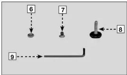
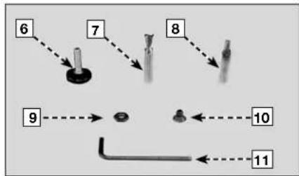
4211 4213 4215
text_image
1
~
E
2
3
4
5

text_image
1
2
3
4
5

text_image
1
2
3
4
5
text_image
10
6
7
8
9
flowchart
graph TD
    A["6"] --> B[" "]
    C["7"] --> D[" "]
    E["8"] --> F[" "]
    G["9"] --> H[" "]
flowchart
graph TD
    A["6"] --> B["7"]
    B --> C["8"]
    C --> D["9"]
    D --> E["10"]
    E --> F["11"]
    style A fill:#f9f,stroke:#333
    style B fill:#ccf,stroke:#333
    style C fill:#cfc,stroke:#333
    style D fill:#fcc,stroke:#333
    style E fill:#cff,stroke:#333
    style F fill:#ffc,stroke:#333
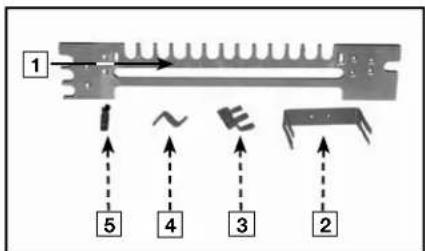
- Half-blind & Sliding Dovetail Template
- Brackets (2)
- Dado Depth Bracket
- Half-blind Depth Bracket
- Dovetail Bit
- Depth Knob
- Screws (8)
- Hex Nuts (1)
- Wrench
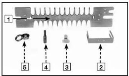
-
Template Guide and Lock Nut
-
Through and Box Joint Template
- Brackets (2)
- Half-Blind Depth Bracket
- Straight Bit
- Template Guide and Lock Nut
- Hex Nuts (1)
- Screws (6)
- Depth Knob
-
Wrench
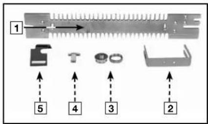
-
Miniature Half-blind, Through, & Box Template
- Brackets (2)
- Template Guide and Lock Nut (2)
- Half-blind Depth Bracket
- Offset Guide (2)
- Depth Knob
- Dovetail Bit
- Straight Bit
- Hex Nuts (1)
10.Screws (6)
11.Wrench
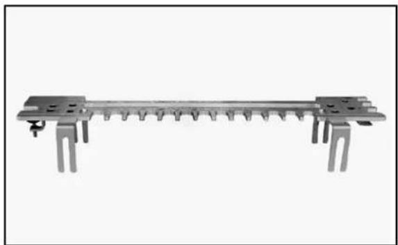
ASSEMBLY
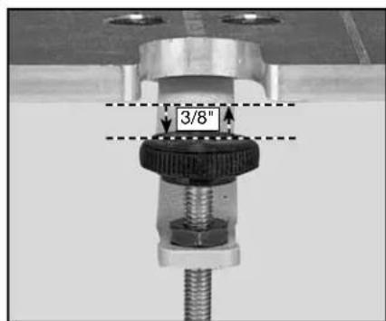
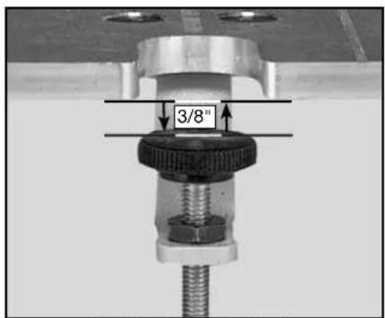
The 4200 series dovetail jigs come fully assembled from the factory. However, the accessory templates (4211, 4213, 4215) require assembly. The supplied hex wrench can be used to attach the brackets and router bit depth guides to the template. A 3/8" wrench is required to adjust the height of the router bit depth guide.
natural_image
Pure mechanical component diagram without any text, numbers, or symbols
ASSEMBLED JIG
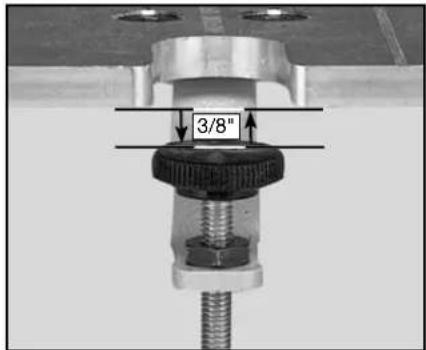
text_image
3/8"
HEIGHT ADJUSTMENT
NOTE: Before setting your router bit to depth, the depth stop should be set at 3/8" below the bottom of the template, as shown above. This is true for all templates.
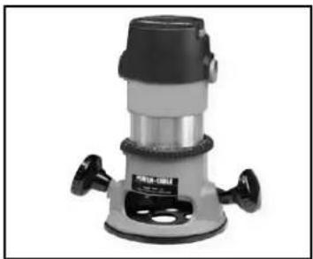
The router that you use with this jig
must accept the Porter-Cable template guides supplied with the jig. (Adapters and sub-bases are available for most routers.)
must have a 1/2" collet for use with 4210 and 4212 jigs and the 4211 and 4213 accessory kits.
◆ must have a 1/4" collet for use with the 4215 accessory kit.
natural_image
Exterior view of a mechanical vacuum cleaner (no visible text or symbols)
NOTE: While the jigs and accessory kits include the router bits and template guides to make the basic dovetail joints, additional router bits are required to make box joints.
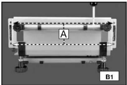
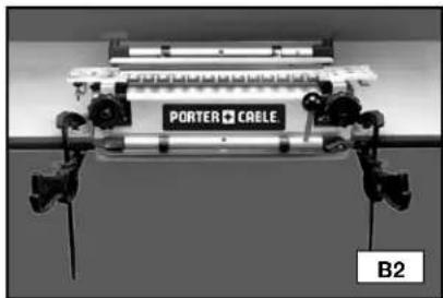
MOUNTING INSTRUCTIONS
NOTE: Always mount your jig to a solid work surface.
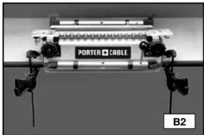
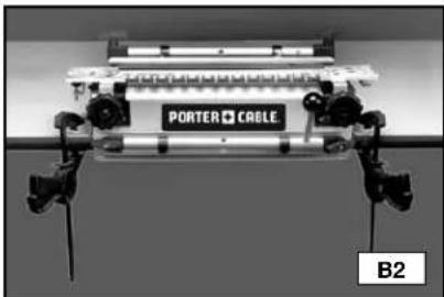
You can mount your jig permanently (Fig. B1) by using the pre-drilled holes (A) Fig B1) on each side of the base, or you can mount the base to your work surface using clamps (Fig. B2).
natural_image
Mechanical setup with labeled components A and B1, no readable text or symbols beyond labels
9
natural_image
Close-up of a mechanical device labeled 'PORTER CABLE' with visible mounting brackets and no readable text or symbols beyond the label.
OPERATION
Mount your workpiece in the jig properly. If the workpiece is not secure, it can be damaged when it moves.
The jigs utilize two mounting positions for workpieces - horizontal and vertical. Some joints require both, while others require the use of a scrap board in the horizontal position (upper clamp) and the workpiece in the vertical position (lower clamp).
Position your workpiece correctly left-to-right to produce symmetrical and tight-fitting joints.
Tear-out from the router bit can be reduced when scrap wood is positioned properly against the workpiece.
CLAMPS
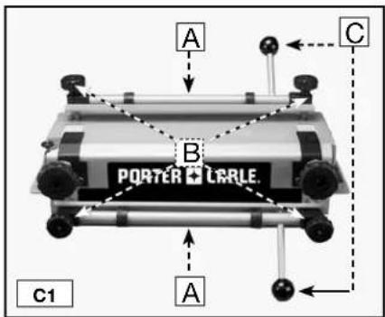
The 4200 series jigs are equipped with two cam-action clamps (A) Fig. C1 with knobs (B) to adjust for workpiece thickness, and levers (C) for quick clamping and releasing of workpieces.
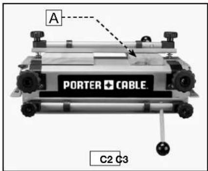
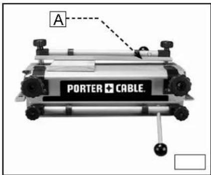
NOTE: Use a scrap board (A) Fig. C2 to prevent misalignment (A) Fig. C3.
text_image
A
B
PORTER LARLE
C1
A
C
text_image
A
PORTER CABLE
C2 C3
text_image
A
PORTER CABLE.
TEMPLATE MOUNTING
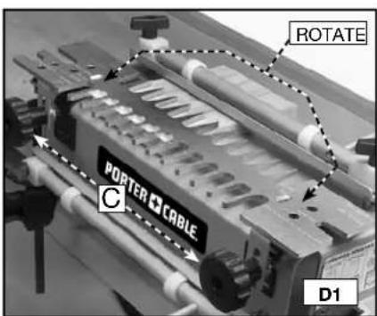
You can mount the templates in two positions on the jig(s) which allows the production of multiple types of joints with each template. To reverse a template, loosen the template knobs (C) Fig. D1, remove the template (B) from the base, rotate it 180 degrees horizontally, replace it on the base, and tighten the template knobs.
NOTE: Secure the templates by inserting the template brackets (A) Fig. D2 between the large template knobs (B) Fig. D2 and the brass adjustment knobs (C). You can then make front-to-back adjustments by loosening the large template knobs (B) and rotating the brass adjustment knobs (C).
text_image
ROTATE
PORTER CABLE
C
D1

text_image
A
B
C
D2
TEMPLATE SUPPORT
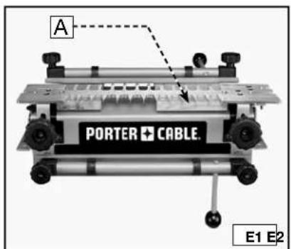
For every type of joint, place wood in the top clamp, whether a workpiece or a scrap piece, to provide support for the router on the template. You can add extra support by inserting a second board (A) Fig. E1 (of the same thickness) in the top clamp to ensure that the template is parallel to the base across its length. This practice works very well for narrow workpieces.
text_image
A
PORTER CABLE.
E1 E2
Supported

natural_image
Industrial machine with labeled 'PORTER + CABLE' and control buttons (no readable text beyond label)
Unsupported
POSITIONING THE WOOD
You must position the workpiece correctly to produce attractive symmetrical joints. Use the offset guides to consistently position the workpiece for optimal alignment and symmetry.
Step 1 - Clamp the workpiece (or spacer board) (A) Fig. F1 in the horizontal position. The position is not critical, but the workpiece must not extend beyond the front edge of the base.
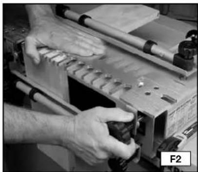
Step 2 - Mount the template (Fig. F2) on top of the horizontal workpiece. Press down on the template (A) with one hand, and tighten the template knobs with the other.
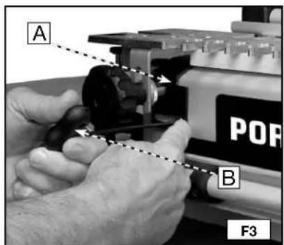
Step 3 - Loosen the left offset guide (A) Fig. F3 with the T-handle hex wrench (B) and move it to the far left position.
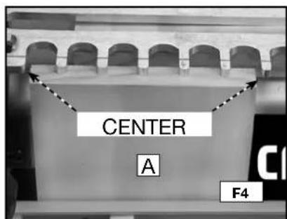
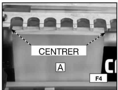
Step 4 Align the vertical workpiece (A) Fig. F4 flush against the bottom side of the template. Center and clamp the workpiece between the farthest finger to the left and the nearest finger to the right of the template.
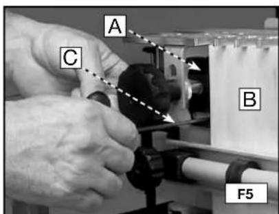
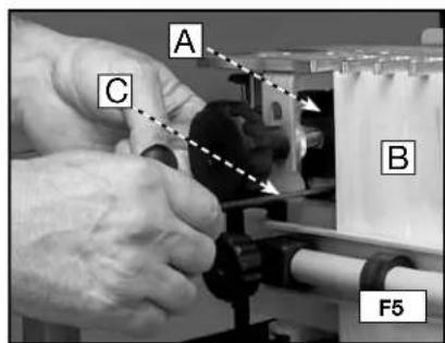
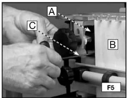
Step 5: Move the left offset guide (A) Fig. F5 to the right so that it is flush against the vertical workpiece (B). Tighten the left offset guide with the T-handle wrench (C).
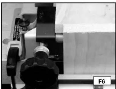
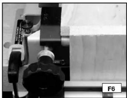
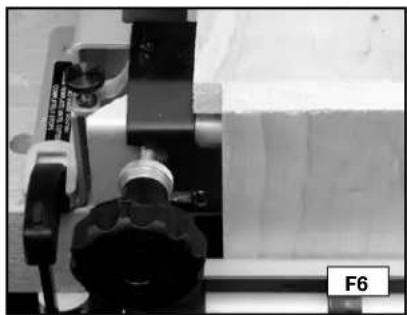
Step 6 Unclamp the horizontal workpiece and slide it forward so that it is flush against the vertical workpiece and flush against the left offset guide (Fig. F6).
NOTE: The template has been removed for clarity.
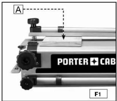
text_image
A
PORTER CAB
F1
natural_image
Close-up of hands operating a mechanical device with tools and components (no visible text or symbols)
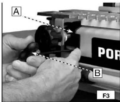
text_image
A
POR
B
F3
text_image
CENTER
A
F4
text_image
A
C
B
F5
natural_image
Close-up of a mechanical device with a tool and component, no visible text or symbols
HALF-PINS VS. HALF-TAILS
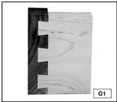
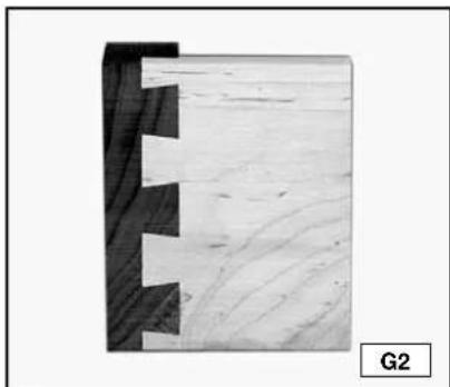
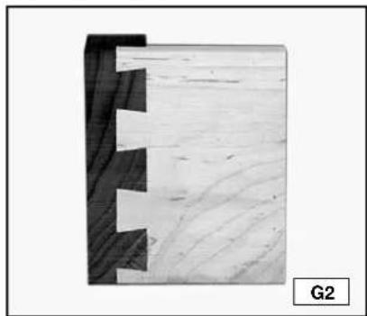
Traditionally, dovetails have half-pins cut on both ends (Fig. G1). Half-tails will be just as strong, but will not be as attractive (Fig. G2). If your joints are half-tails and you want half-pins, move the vertical board 1/2" either left or right, then move the horizontal board accordingly. The procedure is the same with the 4215 Miniature template, except that you move the boards 1/4".
natural_image
Cross-sectional view of a wooden plank with visible grain and cracks, labeled G1 (no text or symbols on the diagram itself)

natural_image
Close-up of a wooden joint with visible grain patterns and cutouts, labeled G2 (no text or symbols on the main subject)
TEAROUT REDUCTION
Tearout is unwanted splintering of the wood fibers that occurs when a router bit enters, exits, or skims the edge of wood and is common to all dovetail jigs. Tearout cannot be eliminated, but it can be reduced by the insertion of additional scrap wood against the workpiece.
ALIGNING THE TEMPLATES
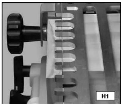
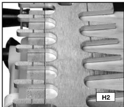
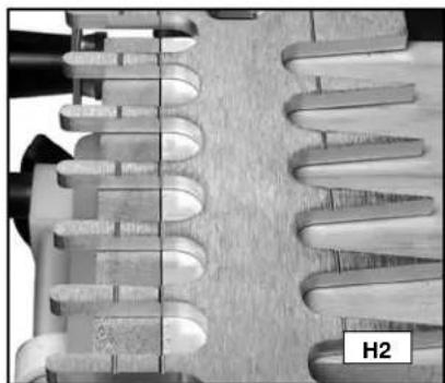
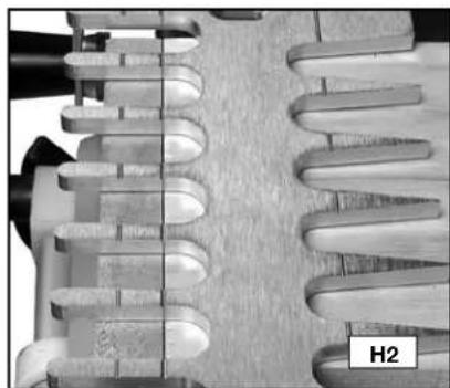
For proper operation, you must align the templates correctly from front to back. The 4200 series jigs have patented alignment lines to help you align the templates without measuring. Some templates have one line (Fig. H1) while others have several lines to produce multiple types of joints (Fig. H2). Porter-Cable has scribed icons on the templates to indicate which lines go with which joints.
natural_image
Close-up of a mechanical device with metallic components and a U-shaped groove (no visible text or symbols)
natural_image
Close-up of a mechanical component with helical grooves and a labeled section H2 (no readable text or symbols)
Adjust the templates front-to-back until the alignment line is directly over the point where the horizontal board and the vertical board meet.
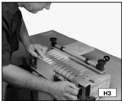
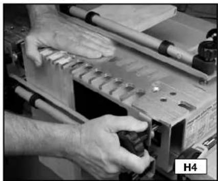
NOTE: To be accurate, lean over the template and look straight down to align the lines (Fig. H3). For the joint to be produced correctly, loosen the knobs on both sides of the template, align the lines, hold the template flat with one hand, and tighten the knobs with the other (Fig. H4).
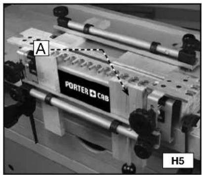
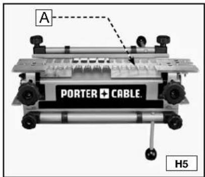
NOTE: To help align both ends of the template when you are using a narrow workpiece, mount an additional piece of wood (of the same thickness) on the far right (A) Fig. H5.
natural_image
Person operating a mechanical press or fixture with tools, no visible text or symbols
natural_image
Close-up of hands operating a wooden cutting machine with metal components (no visible text or symbols)
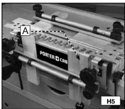
text_image
A
PORTER CAB
H5
TEMPLATE GUIDES
Use the correct template guides provided with this unit to guide the router against the template fingers. To determine the proper guide for a given joint, place the template guide in the slot on the left side of the corresponding template. The guide should have a snug fit in the slot.
natural_image
Close-up of hands adjusting a metallic mechanical component on a wooden workbench (no visible text or symbols)
ROUTER BIT DEPTH
WARNING
DISCONNECT THE ROUTER FROM THE POWER SOURCE BEFORE MAKING ANY CHANGES OR ADJUSTMENTS!
The depth-of-cut for the router bits is critical for a good-fitting joint. The 4200 series jigs have patented router bit depth guides that allow the user to quickly and easily set the bit to the correct depth without measuring.
Rest the router on the left side of the template and gently lower the router bit until it touches the guide. Multiple depth guides are provided on the jig because different joints require different depth settings.
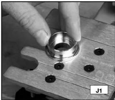
NOTE: Attach the templet guide (with the lock nut) and the bit to your router using the instructions in your router's operating manual.
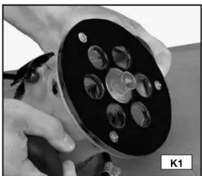
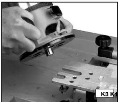
Step 1 - Lower the bit just past the edge of the templet guide (Fig. K1).
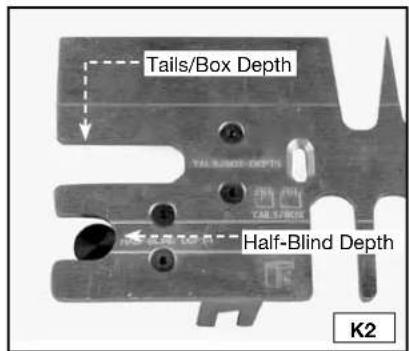
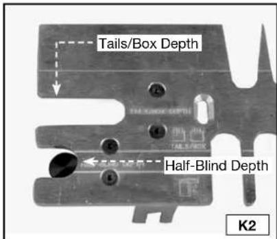
Step 2 - Use the slot with the corresponding scribed text on the template that matches the joint you will cut (Fig. K2).
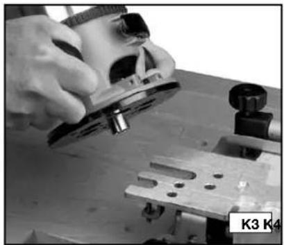
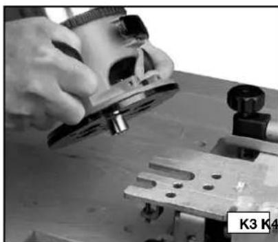
Step 3 - Place the router on the template with the guide and bit in the selected slot (Fig. K3).
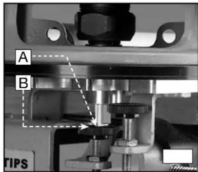
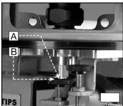
Step 4 - Lower the router bit (A) Fig. K4 on the depth guide (B) and lock the position on your router.
natural_image
Close-up of hands holding a black cylindrical device with multiple circular components (no visible text or symbols)
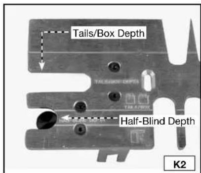
text_image
Tails/Box Depth
Half-Blind Depth
K2
natural_image
Close-up of hands using a plow on a workbench, no visible text or symbols

text_image
A
B
TIPS
WOOD PREPARATION
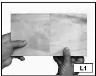
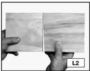
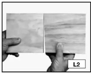
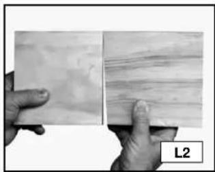
Properly preparing the materials for your project is the key to good-looking and tight-fitting joints. You must cut your wood at perfect right angles (Fig. L1). Cuts that are off even one degree will not align correctly (Fig. L2). Also, your workpieces must be flat and not cupped.
natural_image
Two hands holding a flat surface with visible texture and a label 'L1' in the corner (no other text or symbols)
natural_image
Two hands holding a textured surface, one with visible grain patterns and the other with layered texture (no text or symbols)
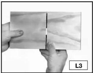
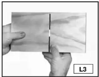
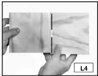
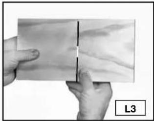
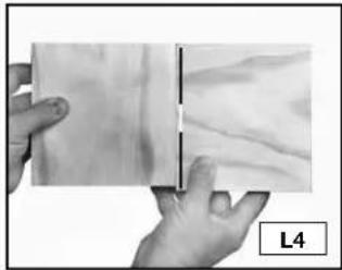
Orient your wood so that end grain is joined to end grain (Fig. L3) to make the joint strong. Using the long grain (Fig. L4) in the workpiece will result in a weak joint.
natural_image
Close-up of hands holding a flat surface with a vertical line, labeled L3 (no text or symbols on the surface itself)
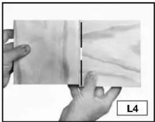
natural_image
Close-up of hands holding a rectangular object with a textured surface, labeled L4 (no text or symbols on the object itself)
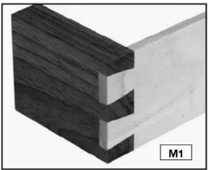
BOARD THICKNESS
NOTE: You can join two workpieces that are different thicknesses (Fig. M1).
The clamps on the 4200 series jigs will hold wood from 1/4" to 1-1/8" thick. Use the following information as a guide to help you decide the thickness of wood for your projects.
natural_image
3D diagram of a wooden joint with visible grain and cutouts, labeled M1 (no text or symbols on the structure itself)
Standard through dovetails....Tail Board Range 1/4" to 1"
Pin Board Range 1/4" to 3/4"
Miniature through dovetails....Both Tails and Pins 1/4" to 1/2" ....
Half-blind dovetails .... Standard and Miniature 1/2" to 1-1/8"
Half-blind dovetail with a lipped front (Pin board will change depending on the size of the lip). 1/2" to 1-1/8"
Standard Box Joints (Limited by router bit length) ....1/4" to 1-1/8"
Miniature Box Joints 1/4" to 1/2"
Sliding Dovetails....1/4" to 1-1/8"
OPTIMAL BOARD WIDTHS
The 4200 series dovetail jigs are capable of making joints up to 12". However, some widths will produce a more attractive joint than others. The optimal widths for creating dovetails are in 1" increments plus 1/4" (1-1/4", 2-1/4", 3-1/4", etc.). Other widths will work, but will not be as attractive.
NOTE: If you are using the 4215 miniature accessory kit, the optimal widths are in 1/2" increments plus 1/8" (5/8", 1-1/8", 1-5/8", etc.).
BOARD LENGTHS
For through dovetails and box joints, cut your workpieces to the same length as the outside dimension of your final project. However, cut the drawer sides (tail board) of half-blind joints as indicated below because the wood does not go all the way through the joint.
To calculate the length of the half-blind tail board, take the inside dimension of the final project and add the router bit depth of cut. If the tail board has a half-blind on both ends, double the added dimension. The length of the pin boards (drawer front) remains the same.
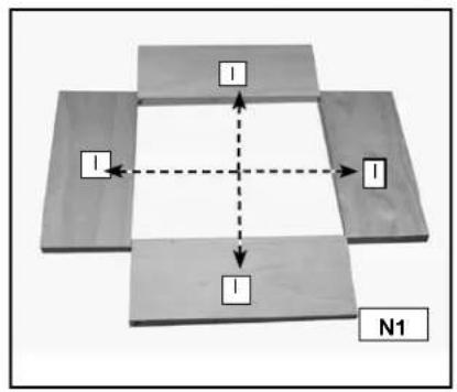
PROJECT LAY OUT
Keeping track of the outer and inner face of each workpiece and how the different parts mate with each other is very important.
Step 1 - Lay out the workpieces face down and label the inside faces with an "I" (Fig. N1).
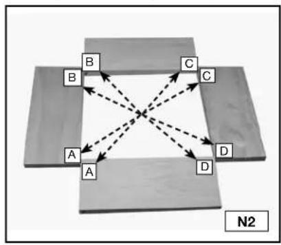
Step 2 - Label the corners "A", "B", "C", and "D" (Fig. N2).
Step 3 - Label the tail boards (drawer sides) with a "T" (Fig. N3).
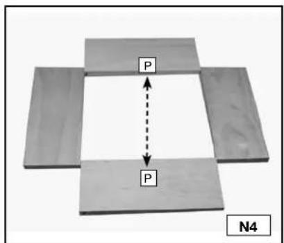
Step 4 - Label the pin boards (drawer fronts) with a "P" (Fig. N4)
flowchart
graph TD
    A["Block 1"] --> B["Block 2"]
    B --> C["Block 3"]
    C --> D["Block 4"]
    D --> A
    style A fill:#f9f,stroke:#333
    style B fill:#f9f,stroke:#333
    style C fill:#f9f,stroke:#333
    style D fill:#f9f,stroke:#333
    linkStyle 0 stroke:#000,stroke-width:2px
    linkStyle 1 stroke:#000,stroke-width:2px
    linkStyle 2 stroke:#000,stroke-width:2px
    linkStyle 3 stroke:#000,stroke-width:2px
    linkStyle 4 stroke:#000,stroke-width:2px
    linkStyle 5 stroke:#000,stroke-width:2px
    linkStyle 6 stroke:#000,stroke-width:2px
    linkStyle 7 stroke:#000,stroke-width:2px
    linkStyle 8 stroke:#000,stroke-width:2px
    linkStyle 9 stroke:#000,stroke-width:2px
    linkStyle 10 stroke:#000,stroke-width:2px
    linkStyle 11 stroke:#000,stroke-width:2px
    linkStyle 12 stroke:#000,stroke-width:2px
    linkStyle 13 stroke:#000,stroke-width:2px
    linkStyle 14 stroke:#000,stroke-width:2px
    linkStyle 15 stroke:#000,stroke-width:2px
    linkStyle 16 stroke:#000,stroke-width:2px
    linkStyle 17 stroke:#000,stroke-width:2px
    linkStyle 18 stroke:#000,stroke-width:2px
    linkStyle 19 stroke:#000,stroke-width:2px
    linkStyle 20 stroke:#000,stroke-width:2px
flowchart
graph TD
    A["A"] --> B["B"]
    A --> C["C"]
    A --> D["D"]
    B --> C
    B --> D
    C --> D
    style A fill:#f9f,stroke:#333
    style B fill:#ccf,stroke:#333
    style C fill:#cfc,stroke:#333
    style D fill:#fcc,stroke:#333
    linkStyle 0 stroke:#000,stroke-width:2px
    linkStyle 1 stroke:#000,stroke-width:2px
    linkStyle 2 stroke:#000,stroke-width:2px
    linkStyle 3 stroke:#000,stroke-width:2px
    linkStyle 4 stroke:#000,stroke-width:2px
    linkStyle 5 stroke:#000,stroke-width:2px
    linkStyle 6 stroke:#000,stroke-width:2px
    linkStyle 7 stroke:#000,stroke-width:2px
    linkStyle 8 stroke:#000,stroke-width:2px
    linkStyle 9 stroke:#000,stroke-width:2px
    linkStyle 10 stroke:#000,stroke-width:2px
    linkStyle 11 stroke:#000,stroke-width:2px
    linkStyle 12 stroke:#000,stroke-width:2px
    linkStyle 13 stroke:#000,stroke-width:2px
    linkStyle 14 stroke:#000,stroke-width:2px
    linkStyle 15 stroke:#000,stroke-width:2px
    linkStyle 16 stroke:#000,stroke-width:2px
    linkStyle 17 stroke:#000,stroke-width:2px
    linkStyle 18 stroke:#000,stroke-width:2px
    linkStyle 19 stroke:#000,stroke-width:2px
    linkStyle 20 stroke:#000,stroke-width:2px
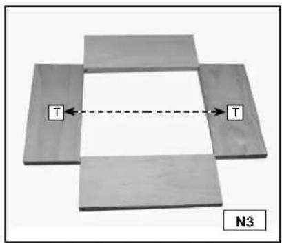
text_image
T
T
N3
DRAWERS
Tips for making drawers:
Tails (A) Fig. O1 are cut into the sides of the drawers, while pins (B) Fig. O1 are cut into the fronts and backs of drawers.
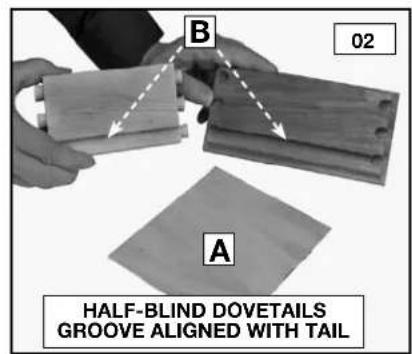
You can use either solid wood or plywood for the drawer bottoms (A) Fig. O2. Insert the bottoms in a groove along the bottom of the fronts and sides. Allow the drawer bottom to be free-floating (without glue) to allow for seasonal expansion and contraction.
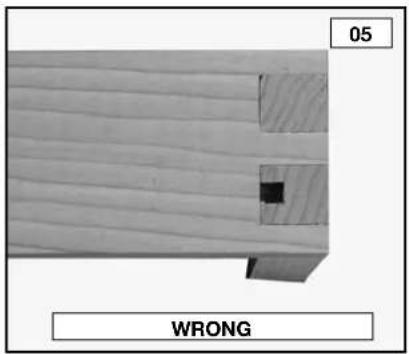
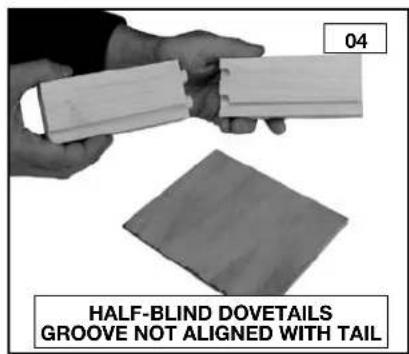
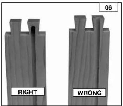
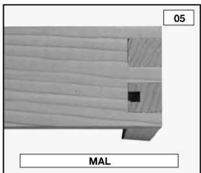
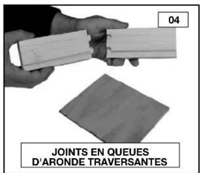
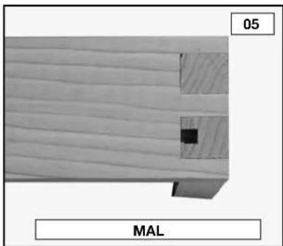
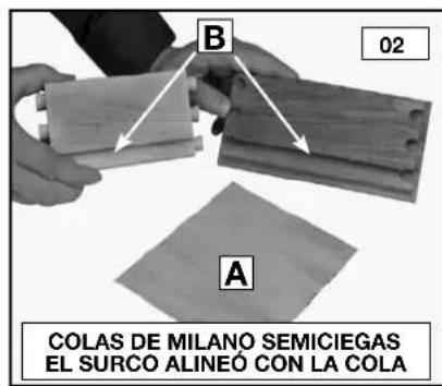
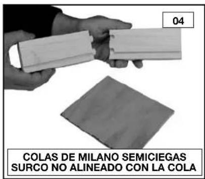
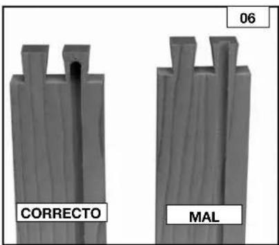
The grooves can go all the way to the ends of the boards if the joints are half-blind dovetails. To accomplish this, position the groove so that it runs through one of the tails on the side (Fig. O2). You will have to stop the grooves on through dovetails or box joints before they reach the end of the board to prevent them from being seen (Figs. O5 and O6).
text_image
P
P
N4
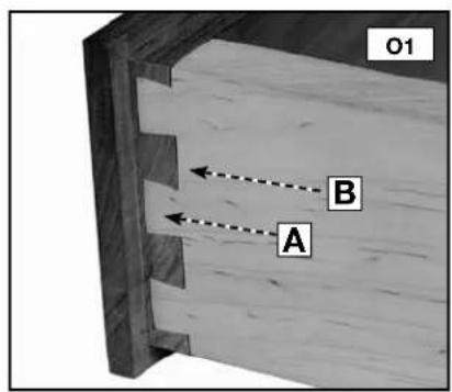
text_image
O1
B
A
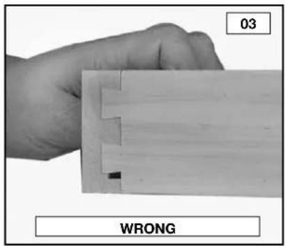
text_image
03
WRONG
text_image
05
WRONG
text_image
B
02
A
HALF-BLIND DOVETAILS
GROOVE ALIGNED WITH TAIL
text_image
04
HALF-BLIND DOVETAILS
GROOVE NOT ALIGNED WITH TAIL
text_image
06
RIGHT
WRONG
BASIC JOINTS
THROUGH DOVETAILS
The through dovetail has a look that is visually appealing, especially in boxes and chests.
NOTE: For miniature through dovetails, use the 4215 accessory kit.
Cut both the pins and tails in the vertical position.
Cut the tails first.
Use two routers (if possible) - one for the pins and the other for the tails - to make the process quicker and easier.
If you are using the 4210 dovetail jig, you will need the 4213 accessory kit to make this joint.
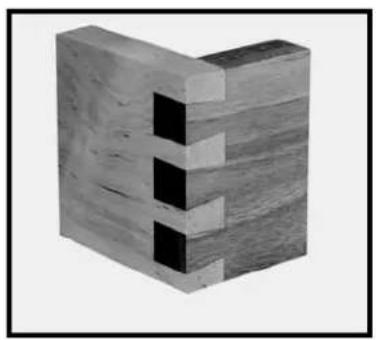
natural_image
3D rendering of a wooden block structure with visible cutouts (no text or symbols)
ITEMS NEEDED
● Through Dovetail and Box Joint Template
• 17/32", 7° Dovetail Bit 43776PC
• 13/32" Straight Bit, 43743PC
● 3/4" O.D. Template Guide, 42040 (with dovetail bit)
- 5/8" O.D. Template Guide, 42046 (with straight bit)
- Template Guide Lock Nut, 42239
ITEMS NEEDED FOR MINIATURE
- Miniature Dovetail Template
● 9/32", 7° Dovetail Bit 43777PC
- 3/16" Straight Bit, 43014PC
● 3/8" O.D. Template Guide, 42037 (with dovetail bit)
- 5/16" O.D. Template Guide, 42055 (with straight bit)
- Template Guide Lock Nut, 42239
CUTTING THE TAILS
Step 1 - Clamp a spacer board (A) Fig. P1 (equal to the thickness of your pinboard) in the upper clamp. Mount the through dovetail template (B) on the base with the "tails" side facing you.
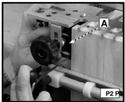
Step 2 - Move the offset guide (A) Fig. P2 to the far left.
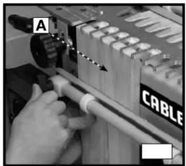
Step 3- Clamp the tailboard (A) Fig. P3 in the lower clamp with the outside surface of the board facing the jig. (See the section "POSITIONING THE WOOD" in this manual.)
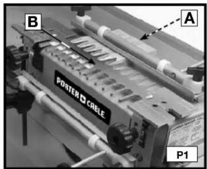
text_image
B
PORTER CABLE
A
P1
natural_image
Close-up of a hand operating a mechanical device with labeled parts (A and P2), no readable text or symbols beyond labels.
natural_image
Close-up of hands operating a cable tool with a wooden handle (no visible text or symbols)
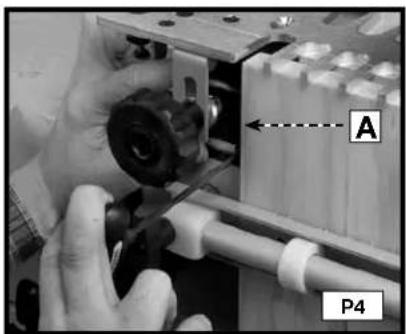
Step 4 - Reposition the offset guide (A) Fig. P4 flush to the vertical board and secure it.
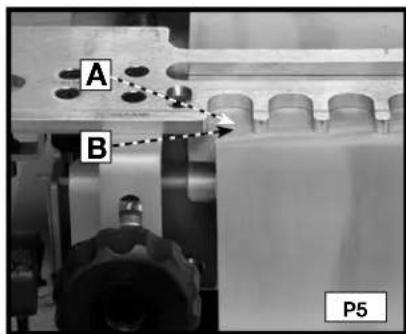
Step 5 - Reposition the scrap board(A) Fig. P5 so that it is flush with the rear edge of the vertical board (B).
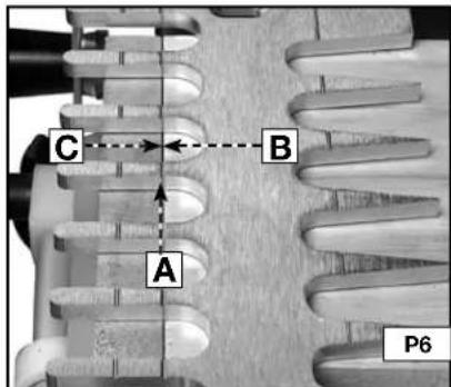
Step 6- Align the template using the "tails/box" line (A) Fig. P6 with the line formed where the scrap board (B) and the vertical board meet (C) and secure it.
text_image
A
P4
text_image
A
B
P5
text_image
C
B
A
P6
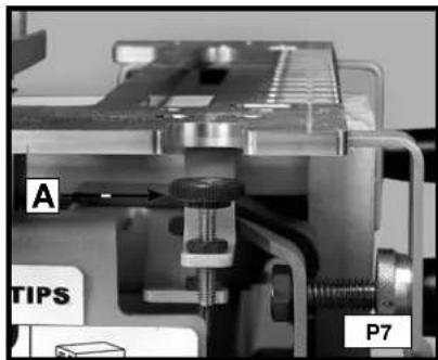
Step 7 - Mount the dovetail bit and 3/4" template guide on the router and set the router bit depth using the "tail/box" depth guide (A) Fig. P7.
Step 8 - Rout along the template fingers (Fig. P8). When the cut is complete, remove the vertical board.
text_image
A
TIPS
P7

natural_image
Close-up of hands operating a mechanical device with a circular component, no visible text or symbols
NOTE: If you prefer for your pins to protrude slightly for easier sanding, Adjust your router for a slightly deeper cut. Once your optimum depth has been achieved, adjust the bit height guide with a 3/8" wrench.
CUTTING THE PINS
NOTE: If the pin board is not the same thickness as the tail board, replace the scrap piece in the horizontal clamp with a scrap board the same thickness as your tail board.
Step 1- Remove the template and rotate it 180 degrees so that the "pins" side is facing you. Clamp the pin board in the lower clamp, flush against the left offset guide with the outside of the board facing away from the jig.
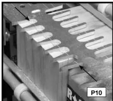
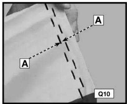
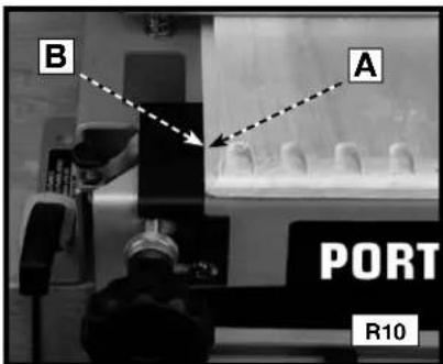
Step 2 - Align the "pins" line (see the arrows) Fig. P10 on the template with the line formed where the scrap board and pin board meet and tighten the template in place.
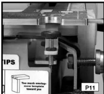
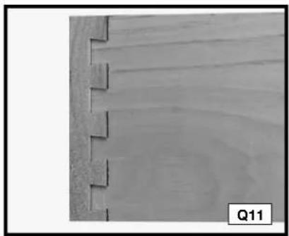
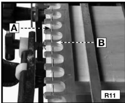
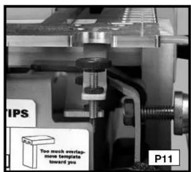
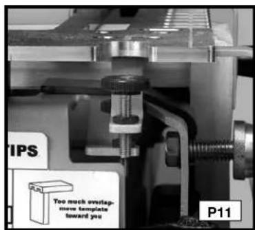
Step 3- Mount the straight bit and the 5/8" templet guide on the router and set the router bit depth using the "pins" bit depth guide (Fig. P11).
natural_image
Close-up of a mechanical component with multiple oval-shaped cutouts and a labeled section P10 (no readable text or symbols)
text_image
TIPS
Too much overlap,
more templates
toward you
P11
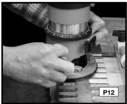
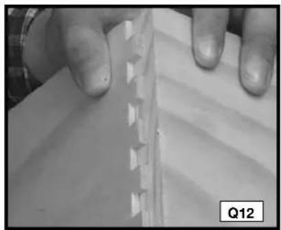
Step 5- Rout between the fingers of the template (Fig. P12).
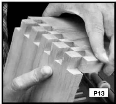
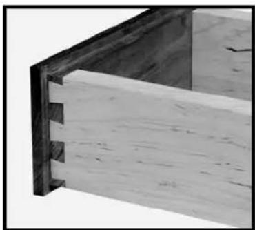
Step 6 - Remove the pin board and check the fit with the tailboard (Fig. P13).
natural_image
Close-up of hands operating a mechanical device with a circular component, labeled P12 (no visible text or symbols on the device itself)
natural_image
Close-up of hands assembling or folding a wooden block structure (no visible text or symbols)
THROUGH DOVETAIL TROUBLESHOOTING
For joints that are too loose, move the template toward you slightly. For joints that are too tight, move the template away from you slightly.
HALF-BLIND DOVETAILS
The half-blind dovetail is one of the most common types of joints and is the ideal choice for the drawer construction. In typical half-blind drawer construction, the joint is not visible from the front and is invisible when the drawer is closed.
NOTE: For miniature half-blinds, use the 4215 accessory kit.
Use scrap wood until you are comfortable with the jig.
You can cut half-blind pins and tails simultaneously on the 4200 series jigs.
Mount the correct offset guides - black for the standard and silver for the miniature.

natural_image
3D rendering of a wooden block with visible grain patterns (no text or symbols)
ITEMS NEEDED
● Half-blind Dovetail Template
• 17/32", 7° Dovetail Bit 43776PC
● 3/4" O.D. Template Guide, 42040
- Template Guide Lock Nut, 42239
ITEMS NEEDED FOR MINIATURE
- Miniature Dovetail Template
• 9/32", 7° Dovetail Bit 43777PC
- 3/8" O.D. Template Guide, 42037 (with dovetail bit)
- Template Guide Lock Nut, 42239
● Miniature Offset Guides (silver)
CUTTING HALF-BLIND DOVETAILS
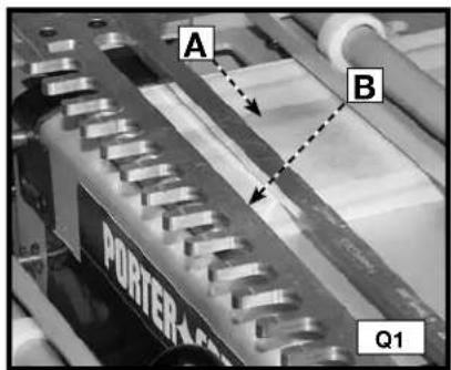
Step 1 - Clamp the pin board (drawer front) (A) Fig. Q1 in the upper clamp (horizontal mounting position) with the outside of the board facing the jig.
Step 2 - Secure the template (B) on top of the pin board. Ensure the flatness by holding one hand on the template and using the other to tighten the template knobs.
Step 3 - Move the left offset guide all the way to the left. (Use the black offset guides for the standard cut, and the silver for the miniature cut).
text_image
A
B
PORTER
Q1
natural_image
Close-up of hands assembling a mechanical component with a tool (no visible text or symbols)
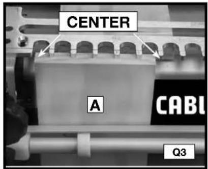
Step 4 - Clamp the tailboard (drawer side) in lower clamp (vertical position) on the left side of the base with the outside of the board facing the jig (A) Fig. Q3.
Step 5 - Center the board between the farthest finger on the left and the nearest finger on the right of the board.
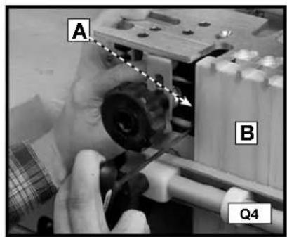
Step 6 - Move the left offset guide (A) Fig. Q4 flush against the vertical board (B) and secure it.
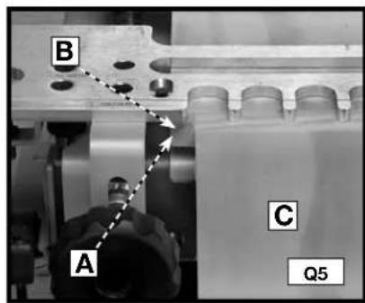
Step 7 - Reposition the pin board (B) Fig. Q5 so that it is flush against the offset guide (A) and the back edge of the vertical board (C).
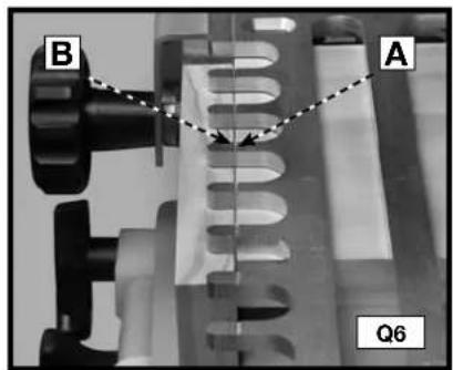
Step 8 - Align the template lines with the intersection of the pin board (A) Fig. Q6 and tail board (B).
Step 9 - Set the router bit depth using the bit-depth guide (A) Fig. Q7.
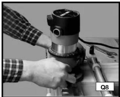
Step 10 - Climb cut (from right to left) the outer edge of the vertical board (Fig. Q8) to reduce tearout.
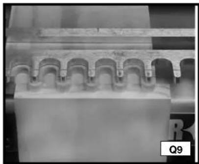
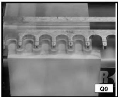
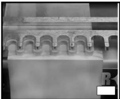
Step 11 - Rout along the fingers of the template (Fig. Q9). Remove the boards from the jig and test for fit.
text_image
CENTER
A
CABI
Q3
text_image
A
B
Q4
text_image
B
A
C
Q5
text_image
B
A
Q6

text_image
A
TIPS
Q7
natural_image
Close-up of a hand operating a mechanical presser or drill bit on a workbench, no visible text or symbols.
natural_image
Close-up of a mechanical component with repeating arches and grooves (no visible text or symbols)
FITTING AND TROUBLESHOOTING
For joints that are too loose, adjust your router to make a deeper cut. (Measure the gap (A) Fig. Q10 in the test cut and adjust the router for that amount).
For joints that are too tight, adjust your router to make a more shallow cut.
Once you achieve the correct depth, secure the router bit depth guide in place with a 3/8" wrench.
If the drawer front overlaps the drawer side, reposition the template toward you (Fig. Q11).
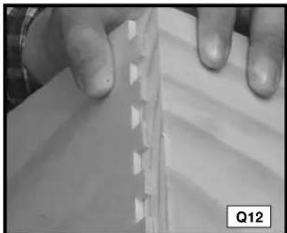
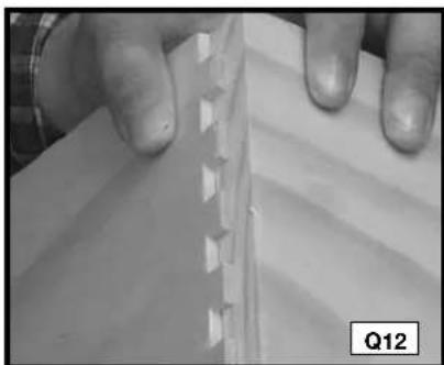
If the drawer front is recessed from the edge of the drawer side (Fig. Q12), reposition the template away from you.
text_image
A
A
Q10
natural_image
Close-up of a wooden plank with visible grain and cutouts, labeled Q11 (no text or symbols on the plank itself)
natural_image
Close-up of hands holding a piece of paper with a serrated edge, no visible text or symbols
RABBETED HALF-BLIND DOVETAILS
To produce rabbeted half-blind dovetails (drawer front), cut the pins for a half-blind joint after the drawer front has been rabbeted. The depth of the rabbet must be deeper than the half-blind router bit depth guide.
NOTE: Cut the tails first.
For miniature half-blinds, use the 4215 accessory kit.
Use scrap wood until you are comfortable with the jig.
Mount the correct offset guides - black for the standard and silver for the miniature.
natural_image
Close-up of a wooden beam joint with visible grain and cutouts (no text or symbols)
ITEMS NEEDED
● Half-blind Dovetail Template
- 17/32", 7° Dovetail Bit 43776PC
● 3/4" O.D. Template Guide, 42040
- Template Guide Lock Nut, 42239
ITEMS NEEDED FOR MINIATURE
● Miniature Dovetail Template
● 9/32", 7° Dovetail Bit 43777PC
● 3/8" O.D. Template Guide, 42037 (with dovetail bit)
- Template Guide Lock Nut, 42239
Miniature Offset Guides (silver)
CUTTING THE TAILS
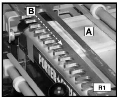
Step 1 - Clamp a scrap board (A) Fig. R1 in the upper clamp (horizontal mounting position). Use scrap board that is thick enough to prevent the bit from contacting the base (1/2" will work). Secure the template (B) on top of the scrap board (Fig. R1). Ensure the flatness by holding one hand on the board and using the other to tighten the template knobs.
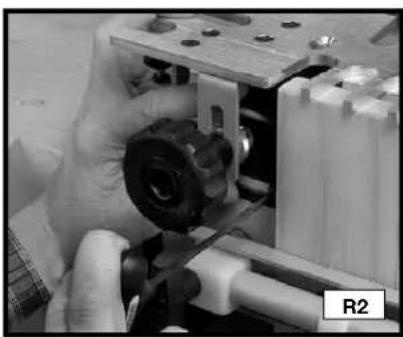
Step 2 - Move the left offset guide all the way to the left (Fig. R2). (Use the black offset guides for the standard cut, and the silver for the miniature cut).
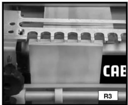
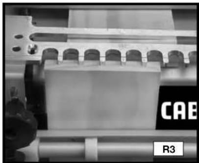
Step 3 - Position and clamp the tail board in the lower clamp (vertical mounting position) with the outside surface against the jig base (Fig. R3).
text_image
B
A
POWER
R1
natural_image
Close-up of hands assembling a mechanical component with visible gears and shafts (no text or symbols)

natural_image
Close-up of a mechanical assembly with rollers and a transparent block, labeled 'R3' (no readable text or symbols beyond labels)
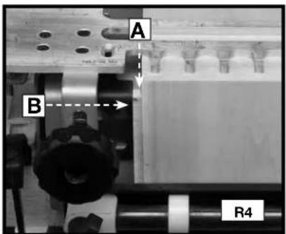
Step 4 - Make a spacer equal to the rabbit's width. Put the spacer (A) Fig. R4 against the left edge of the tail board, move the left offset guide (B) flush against the spacer, and secure the offset guide.
Step 5 - Reposition the scrap board (C) so that it is flush against the offset guide and the back edge of the vertical board.
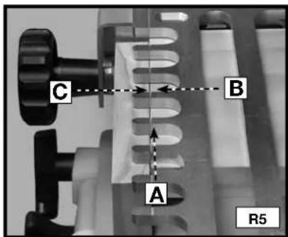
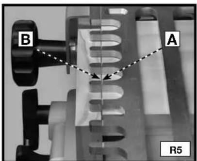
Step 6 - Align the "half-blind" template line (A) Fig. R5 with the line formed where the scrap board (B) and the vertical board (C) meet.
text_image
A
B
R4
text_image
C
B
A
R5
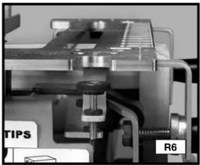
Step 7 - Mount the dovetail bit and template guide to the router and set the router bit depth using the "half-blind" bit depth guide (Fig. R6).
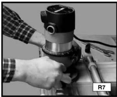
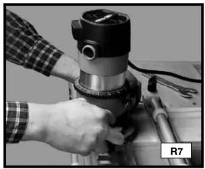
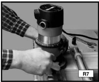
Step 8 - Make a climb-cut from right to left across the outer edge of the tail board to reduce tear-out (Fig. R7).
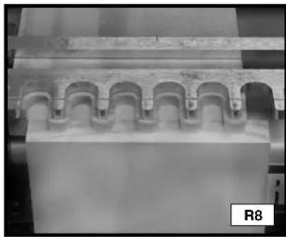
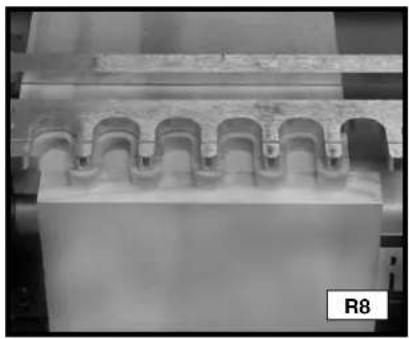
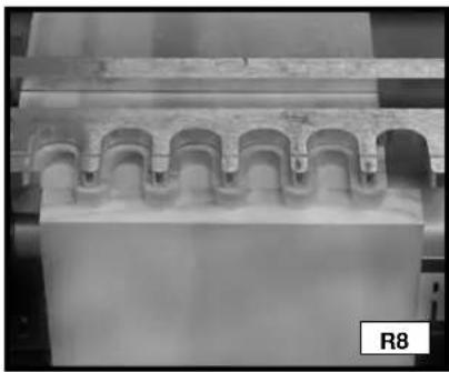
Step 9 - Rout in and out of the fingers of the template from left to right (Fig. R8). Remove the boards.
natural_image
Close-up of a mechanical assembly with labeled parts (TIPS and R6), no readable text or symbols beyond labels
natural_image
Close-up of a hand operating a mechanical presser on a workbench, no visible text or symbols
natural_image
Architectural detail of a building facade with arched eaves and decorative columns (no text or symbols visible)
CUTTING THE PINS
Step 1 - Clamp the pin board in the upper clamp (horizontal mounting position) with the outside surface against the jig's base.
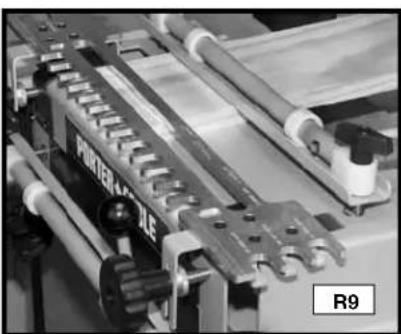
Step 2 - Secure the template on top of the pin board making sure that it is flat (Fig. R9).
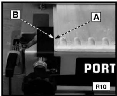
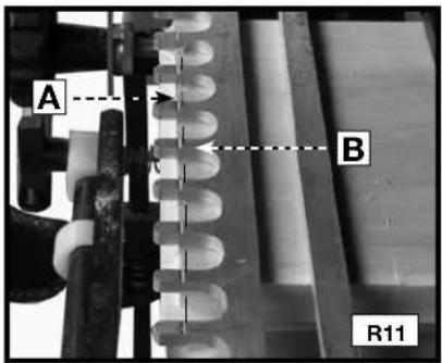
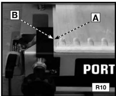
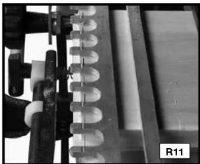
Step 3 - Reposition the pin board (A) Fig. R10 so that it is flush to the left offset guide (B) and the inside edge of the rabbet (A) Fig. R11 is aligned with the "half-blind" alignment line (B). Lower the router bit on the depth guide and lock the position on your router.
Step 4 - Rout in and out of the fingers of the template from left to right.
natural_image
Close-up of industrial machinery components with visible gears and rollers (no readable text or symbols)
text_image
B
A
PORT
R10
text_image
A
B
R11
Step 5 - Remove the boards from the jig and test for fit.
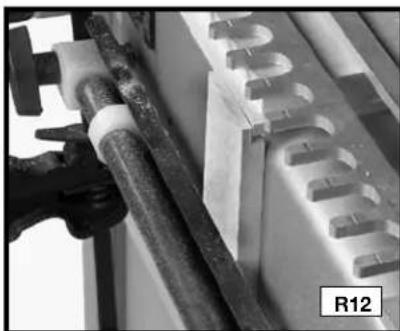
NOTE: Alternate method for aligning the pin board - Use a board with a rabbet the same width as the rabbet on the workpiece (R12).
natural_image
Close-up of a mechanical component with pipes and a textured surface, labeled R12 (no readable text or symbols)
FITTING AND TROUBLESHOOTING
Fitting and troubleshooting methods for the lipped front half-blind dovetail are the same as for the regular half-blind dovetail.
BOX JOINTS
Box joints have straight protrusions that interlock and must be held together by glue. The large amount of gluing surface provides the strength necessary for large projects.
natural_image
3D rendered wooden block structure with no visible text or symbols
NOTE: If you are using the 4210 dovetail jig, you will need the 4213 accessory kit to make this joint. You will need the 4215 accessory kit for the miniature box joints.
Box joint fingers are spaced in 1" increments (1/2" for miniature).
ITEMS NEEDED
● Through Dovetail and Box Joint Template
- 1/2" diameter straight bit (not provided) Length of the cutter must be at least the thickness of the workpiece.
• 3/4" O.D. Template Guide, 42040
• Template Guide Lock Nut, 42239
ITEMS NEEDED FOR MINIATURE
- Miniature Dovetail Template
- 1/4" diameter straight bit (not provided)
At least 1/2" long cutter
● 3/8" O.D. Template Guide, 42037
- Template Guide Lock Nut, 42239
CUTTING THE FIRST WORKPIECE
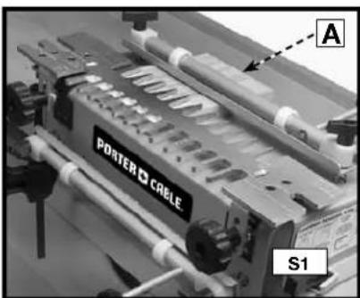
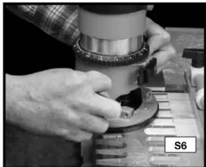
Step 1 - Clamp a scrap board (A) Fig. S1 in the upper clamp (horizontal mounting position) that is the same thickness as the second workpiece.
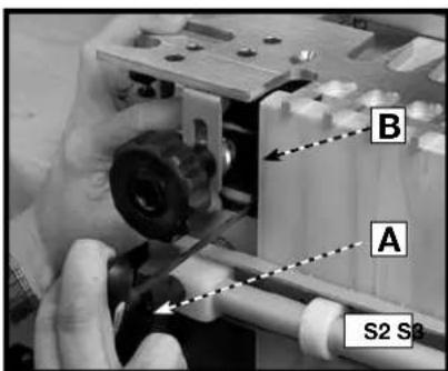
Step 2 - Use the T-handle wrench (A) Fig. S2 to loosen the screw on the left offset guide (B). Move the guide to the far left.
Step 3 - Mount the workpiece (A) Fig. S3 in the lower clamp (vertical mounting position) with the outside surface against the jig base.
text_image
PORTER CABLE
A
S1
text_image
B
A
S2 S3
text_image
A
CABLE
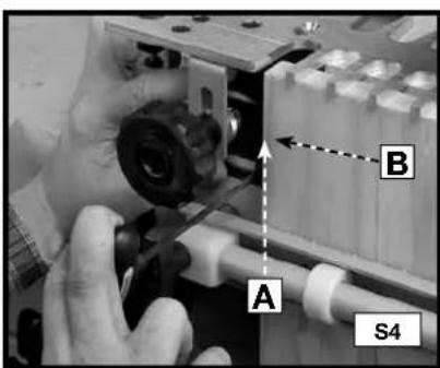
Step 4 - Reposition the left offset guide (A) Fig. S4 flush against the workpiece (B).
Step 5 - Align the template, using the "tails/Box" template line with the line formed where the scrap board and the workpiece meet.
Step 6 - Mount the straight bit and template guide on the router and set the router bit depth using the "tails/box" bit depth guide.
text_image
A
B
S4

natural_image
Close-up of a mechanical component with helical grooves and a labeled section S5 (no readable text or symbols beyond label)
Step 7 - Rout between the fingers of the jig with the templet guide against the left side of the fingers, both in and out. This light pressure toward the left will help to prevent loose joints.
Step 8 - Remove the workpiece from the jig.
natural_image
Close-up of hands operating a mechanical device with a circular component, no visible text or symbols
CUTTING THE SECOND WORKPIECE
NOTE: If the thickness is different between the first and second workpiece, replace the scrap piece in the upper clamp (horizontal Mounting position) with another that is the same thickness as the first workpiece.
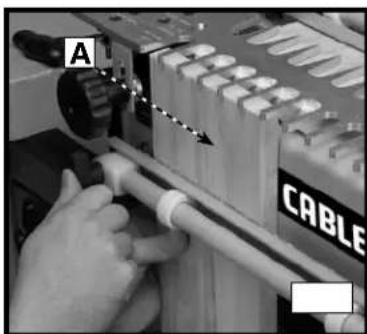
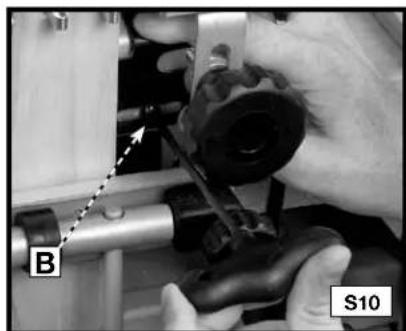
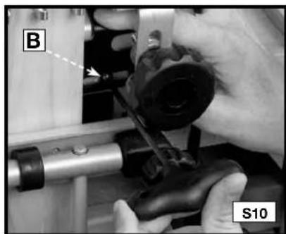
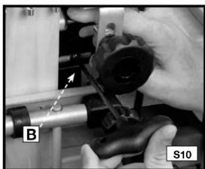
Step 1 - Use the T-handle wrench (A) Fig. S8 to loosen the screw on the right offset guide (B) Fig.S10. Move the guide to the far right.
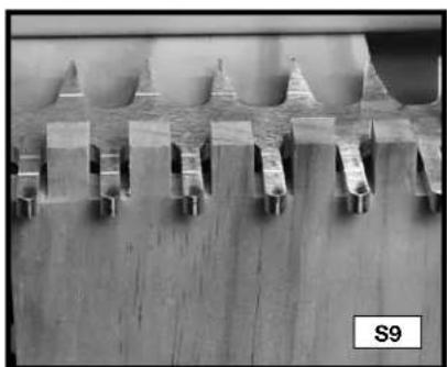
Step 2 - Clamp the first board in the lower clamp on the right side of the jig with the fingers protruding past the template (Fig. S9). Center the protrusions of the wood in between the fingers of the templet.
Step 3 - Move the right offset guide flush against the workpiece and secure it with the T-handle wrench (Fig. S10).
Step 4 - Remove the first workpiece.
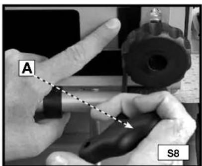
text_image
A
S8
natural_image
Microscopic view of a microstructure with repeating triangular and rectangular features on a wooden surface (no text or symbols visible)
natural_image
Close-up of hands operating a mechanical device with labeled parts (B and S10), no readable text or symbols beyond labels
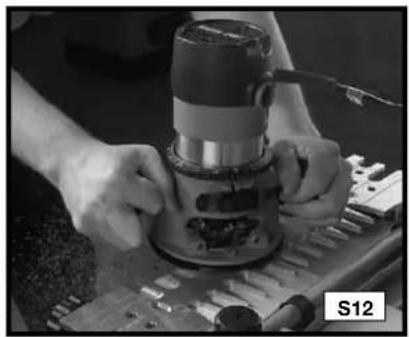
Step 5 - Clamp the second workpiece (A) Fig. S11 in the lower clamp (vertical mounting position) on the right side of the jig flush against both the template (B) and against the right offset guide (C) with the outside surface facing away from the jig.
Step 6 - If the first and second workpieces are of different thicknesses, reset the router bit depth using the "tails/box" bit depth guide.
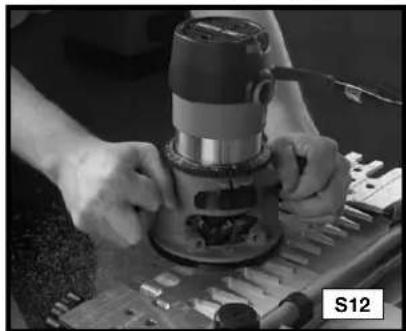
Step 7 - Rout between the fingers of the jig with the templet guide against the left side of the fingers, both in and out. This light pressure toward the left will help to prevent loose joints (Fig. S12).
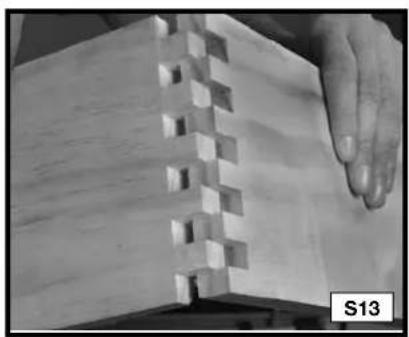
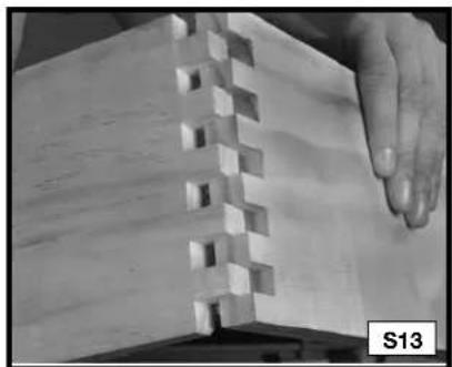
Step 8 - Remove the second workpiece and assemble the joint (Fig. S13)
S11
S12
S13
NOTE: The fit (tightness) of the box joint cannot be adjusted.
SLIDING DOVETAILS
Sliding dovetails are used primarily in the construction of cabinets, entertainment centers and shelving. The 4200 series jigs have three preset depths for dadoes (1/4", 3/8" and 1/2"), but you can manually set your router bit depth to any setting.
NOTE: Be certain that the router bit will not cut into the base or offset guides during this cut. Everything is provided for this cut in both the 4210 and 4212 jigs.
ITEMS NEEDED
- Dado Template
- 17/32", 7° Dovetail Bit 43776PC
• 3/4" O.D. Template Guide, 42040
- Template Guide Lock Nut, 42239
CUTTING THE DADO BOARD
Step 1 - Mark the centerline (A) Fig. T1 of the dado location on the workpiece.
Step 2 - Make two marks 3/8" from the centerline of the dado (B) Fig. T1.
Step 3 - Insert the workpiece (A) Fig. T2 in the upper clamp (horizontal clamping position) and place the dado template (B) on the jig with the dado side facing you. Adjust the template so that the lines that you drew in STEP 2 (C) are aligned exactly with the edges of the slot.
B
C
A
A
T1
B
T2
Step 4 - Set your router bit depth by using either of the three choices (A, B, or C) Fig. T3 on the left side of the template, or by manually setting the router to another depth.
Step 5 - Slowly rout along the slot from left to right (Fig. T4). (Some deep dadoes may require cutting the bulk of the material with a straight bit).
Step 6 - Remove the workpiece.
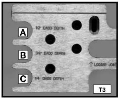
text_image
A
1/2" DADO DEPTH
B
3/4" DADO DEPTH
C
1/4" DADO DEPTH
↑ LOOSER JOIN
T3
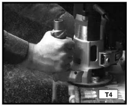
natural_image
Close-up of a hand operating a metal cutting machine (no visible text or symbols)
CUTTING THE TENON BOARD
Step 1 - Mount a scrap board (A) Fig. T6 in the upper clamp (horizontal mounting position)
Step 2 - Mount the tenon board (B) Fig. T6 in the lower clamp (vertical mounting position).
Step 3 - Make a climb cut (from right to left) on the front edge of the template.
Step 4 - Make another cut from left to right along the front edge of the template.
Step 5 - Remove the tenon board. Keep the same end up and turn the board so that the cut side of the board faces the base. Repeat STEPS 3 and 4.
Step 6 - Remove the tenon board and fit the joint.
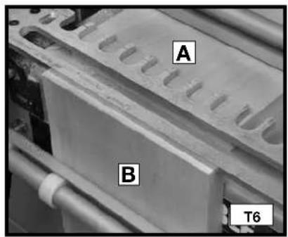
text_image
A
B
T6
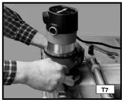
natural_image
Close-up of a hand operating a mechanical presser with tools (no visible text or symbols)
FITTING AND TROUBLESHOOTING
For joints that are too loose, move the template toward you and recut the tenon board.
For joints that are too tight, move the template away from you and recut the tenon board.
TROUBLESHOOTING
For assistance with your tool, visit our website at www.deltaportercable.com for a list of service centers, or call the Porter-Cable Customer Care Center at (888)-848-5175.
MAINTENANCE
Periodically blow out all air passages with dry compressed air. All plastic parts should be cleaned with a soft damp cloth. NEVER use solvents to clean plastic parts. They could possibly dissolve or otherwise damage the material.
⚠ WARNING Wear ANSI Z87.1 safety glasses while using compressed air.
SERVICE
REPLACEMENT PARTS
Use only identical replacement parts. For a parts list or to order parts, visit our company's service website at www.deltaportercableservicenet.com. You can also order parts from your nearest factory-owned branch, or by calling our Customer Care Center at 1-888-848-5175 to receive personalized support from highly-trained technicians.
FREE WARNING LABEL REPLACEMENT
If your warning labels become illegible or are missing, call 1-800-223-7278 for a free replacement.

text_image
Model 4210
12" Dovetail Jig
WARNING TO REDUCE THE RISK OF INJURY. USER
MUST READ INSTRUCTION MANUAL
BEFORE OPERATING PRODUCT.
Ser. No.
AVERTISSEMENT AFIN DE RÉDUIRE LE BISQUE
DE BLESSURES, L'UTILISATEUR
DOIT LIRE LE MODE D'EMPLOI AVANT D'UTILISER LE PRODUIT.
ADVERTENCIA PARA REDUCIR EL RIESGO DE
LESIONES, EL USUARIO DEBE LEER
PORTER-CABLE, Jackson TN 58305 EL MANUAL DE INSTRUCCIONES ANTES DE OPERAR EL PRODUCTO.
SERVICE AND REPAIRS
All quality tools will eventually require servicing and/or replacement of parts. For information about Porter-Cable, its factory-owned branches, or an Authorized Warranty Service Center, visit our website at www.deltaportercable.com or call our Customer Care Center at (888)-848-5175. All repairs made by our service centers are fully guaranteed against defective material and workmanship. We cannot guarantee repairs made or attempted by others.
You can also write to us for information at PORTER-CABLE, 4825 Highway 45 North, Jackson, Tennessee 38305 - Attention: Product Service. Be sure to include all of the information shown on the nameplate of your tool (model number, type, serial number, etc.).
ACCESSORIES
A complete line of accessories is available from your Porter-Cable•Delta Supplier, Porter-Cable•Delta Factory Service Centers, and Porter-Cable Authorized Service Stations. Please visit our Web Site www.deltaportercable.com for a catalog or for the name of your nearest supplier.
⚠ WARNING Since accessories other than those offered by Porter-Cable•Delta have not been tested with this product, use of such accessories could be hazardous. For safest operation, only Porter-Cable•Delta recommended accessories should be used with this product.
WARRANTY
PORTER-CABLE will repair, without charge, any defects due to faulty materials or workmanship for three years from the date of purchase. This warranty does not cover part failure due to normal wear or tool abuse. For further detail of warranty coverage and warranty repair information, visit www.deltaportercable.com or call (888) 848-5175. This warranty does not apply to accessories or damage caused where repairs have been made or attempted by others. This warranty gives you specific legal rights and you may have other rights which vary in certain states or provinces.
In addition to the warranty, PORTER-CABLE tools are covered by our:
1 YEAR FREE SERVICE: PORTER-CABLE will maintain the tool and replace worn parts caused by normal use, for free, any time during the first year after purchase.
90 DAY MONEY BACK GUARANTEE: If you are not completely satisfied with the performance of your PORTER-CABLE Power Tool, Laser, or Nailer for any reason, you can return it within 90 days from the date of purchase with a receipt for a full refund – no questions asked.
LATIN AMERICA: This warranty does not apply to products sold in Latin America. For products sold in Latin America, see country specific warranty information contained in the packaging, call the local company or see website for warranty information.
To register your tool for warranty service visit our website atwww.deltaportercable.com.
MESURES DE SÉCURITÉ - DÉFINITIONS
Technical Service Manager
Porter-Cable Corporation
4825 Highway 45 North
Jackson, TN 38305
natural_image
Two 3D diagrams showing a folded panel or panel structure with no text or symbols
JOINTS EN QUEUES D'ARONDE SEMI-AVEUGLES AVEC UNE PARTIE AVANT À REBORD
natural_image
Two isometric line drawings of open and closed rectangular panels with visible internal structure (no text or symbols)
JOINT À EMBOÎTEMENT (JOINT À QUEUES DROITES)
natural_image
Two 3D diagrams showing a split rectangular block with internal spring-like notches, no text or symbols present.
QUEUE D'ARONDE COULISSANTE
text_image
Tenon
Dado
CAPACITÉS DES PRODUITS
natural_image
Three mechanical clamps or brackets with metal fittings, shown from different angles (no text or symbols visible)
natural_image
Five mechanical bearing components arranged in a row, no text or symbols visible
natural_image
Two metallic cutting tool holders shown from different angles (no text or symbols visible)
natural_image
Two metallic cutting tool profiles shown from different angles, labeled A5 (no text or symbols on the tools themselves)
CONTENU DU CARTON
APPAREILS À QUEUES D'ARONDE
4210
text_image
PORTER CABLE.
text_image
Diagram showing mechanical components with numbered parts, likely for assembly or manufacturing instructions
natural_image
Mechanical component with multiple supports and a central plate (no visible text or symbols)
GABARIT ASSEMBLÉ
text_image
3/8"
AJUSTEMENT DE TAILLE
natural_image
Exterior view of a precision vacuum cleaner (no visible text or symbols)
natural_image
Mechanical device with labeled components A and B1, showing no readable text or symbols beyond labels
natural_image
Close-up of a mechanical device labeled 'PORTER + CABLE' with mounting brackets and a B2 indicator (no readable text beyond labels)
UTILISATION
natural_image
Industrial machine with labeled 'PORTER + CABLE' and control buttons (no readable text beyond label)
Non supporté
POSITIONNEMENT DU BOIS
natural_image
Close-up of hands operating a mechanical device with tools and components (no visible text or symbols)

text_image
A
POR
B
F3
text_image
CENTRER
A
F4
text_image
A
C
B
F5
natural_image
Close-up of a mechanical assembly with a tool and component, no visible text or symbols
DEMI-TENONS OU DEMI-QUEUES
natural_image
Close-up of a wooden plank with visible grain patterns and cutouts, labeled G1 (no text or symbols on the wood itself)
natural_image
Close-up of a wooden joint with visible grain patterns and cutouts, labeled G2 (no text or symbols on the main subject)
RÉDUCTION DES RISQUES D'ÉCLATEMENT DU BOIS
natural_image
Close-up of a mechanical component with a spring-like structure and a labeled section H1 (no readable text or symbols)
natural_image
Close-up of a mechanical component with helical grooves and a labeled section H2 (no readable text or symbols beyond label)
natural_image
Person operating a mechanical press or fixture with tools, no visible text or symbols

natural_image
Close-up of hands operating a wooden workbench with tools and components (no visible text or symbols)
text_image
A
PORTER CAB
H5
GUIDES DE GABARITS
natural_image
Close-up of a hand adjusting a metallic mechanical component on a workbench (no visible text or symbols)
PROFONDEUR DES MÈCHES DE DÉFONCEUSE
AVERTISSEMENT
natural_image
Close-up of hands holding a black circular object with multiple small transparent spheres, no visible text or symbols.
text_image
Tails/Box Depth
YAL-SUNDO DEPTH
YAL 1/BACK
Half-Blind Depth
K2
natural_image
Close-up of hands using a tool on a workbench, no visible text or symbols
text_image
A
B
RIPS
PRÉPARATION DU BOIS
natural_image
Two hands holding a flat surface with visible texture and minor cracks, labeled L1 (no text or symbols on the surfaces)
natural_image
Close-up of two hands holding a textured surface, one with visible grain patterns and the other with layered texture (no text or symbols)
natural_image
Close-up of hands holding a piece of paper with a dashed line, labeled L3 (no text or symbols on the paper itself)
natural_image
Close-up of hands holding a rectangular object with a dashed line and abstract texture, labeled L4 (no text or symbols on the object itself)
natural_image
3D diagram of a wooden joint with visible grain and cutouts, labeled M1 (no text or symbols beyond label)
natural_image
Diagram of a square frame with two labeled faces (T) and an arrow indicating direction, no text or symbols present.
TIROIRS
natural_image
Close-up of a hand holding a wooden plank with a small inset showing a cut section, labeled 'MAL' (no other text or symbols)
natural_image
Close-up of a wooden plank with visible grain and two small square holes, labeled 'MAL' at bottom (no other text or symbols)
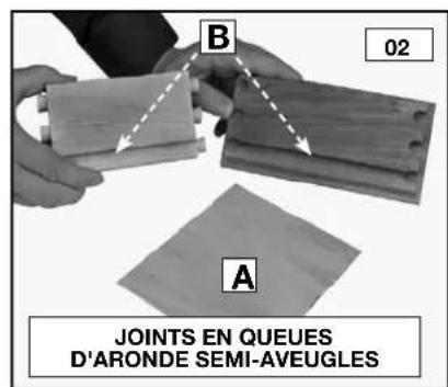
text_image
B
02
A
JOINTS EN QUEUES
D'ARONDE SEMI-AVEUGLES
text_image
04
JOINTS EN QUEUES
D'ARONDE TRAVERSANTES
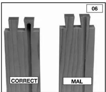
text_image
06
CORRECT
MAL
JOINTS DE BASE
QUEUES D'ARONDE TRAVERSANTES
natural_image
3D rendering of a wooden block with cutouts and a vertical slot (no text or symbols)
PIÈCES NÉCESSAIRES
natural_image
Close-up of hands operating a mechanical device with a circular component, no visible text or symbols
natural_image
Close-up of a mechanical component with multiple slots and pipes, no visible text or symbols
text_image
TIPS
Too much overlap-
more templates
toward you
P11
natural_image
Close-up of hands operating a mechanical device with a circular component, labeled P12 (no visible text or symbols on the device itself)

natural_image
Close-up of hands assembling wooden blocks with visible grain patterns (no text or symbols)
RÉSOLUTION DES PROBLÈMES CONCERNANT LES QUEUES D'ARONDE TRAVERSANTES
natural_image
3D rendering of a wooden joint or block with visible grain patterns (no text or symbols)
PIÈCES NÉCESSAIRES
natural_image
Close-up of hands assembling a mechanical component with a tool (no visible text or symbols)
natural_image
Close-up of a hand operating a drill press machine with tools (no visible text or symbols)
natural_image
Close-up of a mechanical component with repeating arches and a textured surface (no visible text or symbols)
AJUSTAGE ET RÉSOLUTION DES PROBLÈMES
natural_image
Close-up of a wooden plank with visible grain and cutouts, labeled Q11 (no text or symbols on the plank itself)
natural_image
Close-up of hands holding a white sheet with a grid pattern, no visible text or symbols
QUEUES D'ARONDE SEMI-AVEUGLES AVEC UNE PARTIE AVANT À REBORD
natural_image
Close-up of a wooden beam joint with visible grain and bracing (no text or symbols)
PIÈCES NÉCESSAIRES
natural_image
Close-up of hands assembling a mechanical component with a tire and pipe (no visible text or symbols)

text_image
A
B
R4
natural_image
Close-up of a mechanical assembly with rollers and a labeled component (R3), no readable text or symbols beyond labels
text_image
B
A
R5
natural_image
Close-up of a mechanical assembly with labeled parts TIPS and R6 (no readable text or symbols beyond labels)
natural_image
Close-up of a hand operating a mechanical presser or drill bit on a workbench, no visible text or symbols.
natural_image
Close-up of a mechanical component with repeating arch-like grooves, labeled R8 in the corner (no readable text or symbols beyond label)
COUPE DES TENONS
natural_image
Close-up of industrial machinery components with no visible text or symbols
text_image
B
A
PORT
R10
text_image
A
B
R11
natural_image
Close-up of industrial machinery components with visible pipes and blocks (no text or symbols)
AJUSTAGE ET RÉSOLUTION DES PROBLÈMES
natural_image
3D rendered wooden block structure with no visible text or symbols
natural_image
Close-up of a mechanical component with helical grooves and a labeled section S5 (no readable text or symbols)
natural_image
Close-up of hands operating a mechanical device with a circular component, no visible text or symbols
natural_image
Microscopic view of a microfluidic chip array with repeating triangular structures on a wooden surface (no text or symbols visible)
natural_image
Close-up of hands operating a mechanical device with labeled parts (B and S10), no readable text or symbols beyond labels
natural_image
Industrial machine with multiple cylindrical vials and meshed components, no visible text or symbols
natural_image
Close-up of hands operating a machine tool on a workbench, no visible text or symbols
natural_image
Close-up of a wooden plank with visible grain patterns and a hand touching it (no text or symbols)
natural_image
Close-up of a wooden block with a flat top, resting on a wooden base (no text or symbols visible)
natural_image
Close-up of a hand operating a mechanical tool, no visible text or symbols
COUPE DE PLANCHES À TENONS
natural_image
Close-up of a hand operating a mechanical presser or drill bit (no visible text or symbols)
AJUSTAGE ET RÉSOLUTION DES PROBLÈMES
Technical Service Manager
Porter-Cable Corporation
4825 Highway 45 North
Jackson, TN 38305
natural_image
Two 3D diagrams showing a folded panel or panel structure with no text or symbols
COLAS DE MILANO SEMICIEGAS CON UNA PARTE DELANTERA CON REBORDE
natural_image
Two isometric line drawings of open bookshelves or compartments, showing front and side views (no text or symbols)
natural_image
Two 3D diagrams of rectangular blocks with vertical and horizontal notches, no text or symbols present
COLA DE MILANO DESLIZANTE
text_image
Tenon
Dado
CAPACIDADES DEL PRODUCTO
natural_image
Three types of metal electrical connectors or tools arranged vertically (no text or symbols visible)
natural_image
Five mechanical bearing components arranged in a row, one bearing a ring and others with cylindrical heads (no text or symbols visible)

natural_image
Two metallic cutting tool holders shown from different angles, labeled A4 (no text or symbols on the tools themselves)

natural_image
Two metallic cutting tool profiles shown from different angles, labeled A5 (no text or symbols on the tools themselves)
natural_image
Mechanical assembly with a long rod and multiple supports (no visible text or symbols)
MONTADO
text_image
3/8"
AJUSTE DE ALTURA
natural_image
Exterior view of a precision presser or scrubber device (no visible text or symbols)
natural_image
Mechanical setup with labeled components A and B1, no readable text or symbols beyond labels
natural_image
Exterior view of a modern office building (no signage)
UTILIZACIÓN
natural_image
Industrial machine labeled 'PORTER CABLE' with no visible text or symbols on the device itself
Sin soporte
natural_image
Close-up of hands operating a mechanical device with tools and components (no visible text or symbols)
text_image
A
POR
B
F3

text_image
CENTRO
A
F4
text_image
A
C
B
F5
natural_image
Close-up of a mechanical assembly with a tool and component, no visible text or symbols
natural_image
Close-up of a wooden plank with visible grain patterns and a black rectangular cutout, labeled G1 (no text or symbols on the wood itself)
natural_image
Close-up of a wooden plank with visible grain patterns and cutouts, labeled G2 (no text or symbols on the wood itself)
natural_image
Close-up of a mechanical device with a U-shaped component and a label H1 (no readable text or symbols)
natural_image
Close-up of a mechanical component with helical grooves and a labeled section H2 (no readable text or symbols beyond label)
natural_image
Person operating a mechanical press or fixture with tools, no visible text or symbols

natural_image
Close-up of hands operating a mechanical tool with tools and components (no visible text or symbols)
text_image
A
PORTER + CABLE.
H5
GUÍAS DE PLANTILLA
natural_image
Close-up of a hand adjusting a metallic mechanical component with bolt holes (no visible text or symbols)
natural_image
Close-up of hands holding a black cylindrical device with multiple circular components (no visible text or symbols)
text_image
Tails/Box Depth
Half-Blind Depth
K2
natural_image
Close-up of hands using a power tool to work on a mechanical component (no visible text or symbols)
text_image
A
B
TIPS
natural_image
Close-up of two hands holding a flat, textured surface with no visible text or symbols
natural_image
Two hands holding a wooden surface, one showing grain texture and the other with visible grain patterns (no text or symbols)
natural_image
Close-up of hands holding a flat, textured surface with a vertical line and label L3 (no text or symbols on the surface itself)
natural_image
Close-up of hands holding a rectangular object with a vertical line and textured surface, labeled L4 (no text or symbols on the object itself)
GROSOR DE LAS TABLAS
natural_image
3D diagram of a wooden joint with visible grain and cutouts, labeled M1 (no text or symbols beyond label)
natural_image
Close-up of a hand holding a wooden object with a label 'MAL' and page number '03' (no other text or symbols visible)
natural_image
Close-up of a wooden plank with visible grain and two small square holes, labeled 'MAL' at bottom (no other text or symbols)
text_image
B
02
A
COLAS DE MILANO SEMICIEGAS
EL SURCO ALINEÓ CON LA COLA
text_image
04
COLAS DE MILANO SEMICIEGAS
SURCO NO ALINEADO CON LA COLA
text_image
06
CORRECTO
MAL
JUNTAS BÁSICAS
COLAS DE MILANO PASANTES
natural_image
3D rendering of a wooden block with visible grain patterns and cutouts (no text or symbols)
natural_image
Close-up of hands operating a mechanical device with a circular component, no visible text or symbols
natural_image
Close-up of a mechanical component with cutouts and pipes, labeled P10 (no readable text or symbols)
text_image
TIPS
Too much overlap-
more template
toward you
P11
natural_image
Close-up of hands operating a mechanical device with a circular component, labeled P12 (no visible text or symbols on the device itself)

natural_image
Close-up of hands assembling a wooden plank with triangular cutouts (no text or symbols visible)
natural_image
3D rendering of a wooden block with visible grain patterns (no text or symbols)
natural_image
Close-up of hands operating a mechanical device with a black tool, no visible text or symbols
natural_image
Close-up of a hand operating a drill bit machine with tools (no visible text or symbols)
natural_image
Close-up of a mechanical component with repeating arches and grooves (no visible text or symbols)
natural_image
Close-up of a wooden door panel with visible grain and cutouts, labeled Q11 (no text or symbols on the panel itself)
natural_image
Close-up of hands holding a thin, folded paper or plastic sheet with visible grooves and texture (no text or symbols)
COLAS DE MILANO SEMICIEGAS CON UNA PARTE DELANTERA CON REBORDE
natural_image
Close-up of a wooden beam joint with visible grain and cutouts (no text or symbols)
natural_image
Close-up of a hand operating a mechanical component with a circular component, labeled R2 (no visible text or symbols on the main subject)
natural_image
Close-up of a mechanical assembly with rollers and a rectangular block, labeled 'R3' (no readable text or symbols beyond labels)
natural_image
Close-up of a mechanical assembly with labeled parts (TIPS, R6) and no readable text or symbols beyond labels
natural_image
Close-up of a hand operating a mechanical presser or drill bit on a metal workbench (no visible text or symbols)
natural_image
Close-up of a mechanical component with arched cutouts and a labeled section R8 (no readable text or symbols)
CORTE DE LAS ESPIGAS
natural_image
Close-up of industrial machinery with conveyor belts and rollers (no visible text or symbols)
text_image
B
A
PORT
R10
natural_image
Close-up of a mechanical assembly with coiled components and a labeled part R11 (no readable text or symbols)
natural_image
Close-up of industrial machinery components with pipes and blocks, no visible text or symbols
natural_image
3D rendered wooden block structure with visible grain patterns (no text or symbols)
natural_image
Close-up of a mechanical component with helical grooves and a central shaft, labeled S5 (no text or symbols on the main subject)
natural_image
Close-up of hands operating a mechanical device with a circular component, no visible text or symbols
CORTE DE LA SEGUNDA PIEZA DE TRABAJO
natural_image
Microscopic view of microstructures with triangular and rectangular features on a surface (no text or symbols visible)
natural_image
Close-up of hands operating a mechanical tool with labeled parts (B and S10), no readable text or symbols beyond labels
natural_image
Close-up of a mechanical component with multiple cylindrical vials and a labeled section S11 (no readable text or symbols on the main subject)
natural_image
Close-up of hands operating a machine tool on a workbench (no visible text or symbols)
natural_image
Close-up of a wooden mechanical component with visible cutouts, being handled by a hand (no text or symbols)
natural_image
Close-up of a wooden plank with a small rectangular block resting on a flat base (no text or symbols visible)
CORTE DE LA TABLA DE MORTAJA
natural_image
Close-up of a hand operating a metal workpiece in a workshop (no visible text or symbols)
CORTE DE LA TABLA DE ESPIGA
natural_image
Close-up of a hand operating a mechanical presser or drill bit (no visible text or symbols)
Local D, Col. Obrera (55) 5588 9377
MERIDA, YUC
Calle 63 #459-A - Col. Centro (999) 928 5038
MONTERREY, N.L.
Av. Francisco I. Madero No.831 - Col. Centro (81) 8375 2313
PUEBLA, PUE
17 Norte #205 - Col. Centro (222) 246 3714
QUERETARO, QRO
Av. Madero 139 Pte. - Col. Centro (442) 214 1660
SAN LUIS POTOSI, SLP
4825 Highway 45 North
Jackson, TN 38305
(888) 848-5175
www.deltaportercable.com