WinSafe WS 11 - Window lock Burg Wächter - Free user manual and instructions
Find the device manual for free WinSafe WS 11 Burg Wächter in PDF.
| Product type | Window lock |
| Brand | Burg Wächter |
| Model | WinSafe WS 11 |
| Approximate dimensions | Approx. 100 x 40 x 30 mm |
| Approximate weight | Approx. 200 g |
| Material | Steel |
| Color | White / Silver (depending on version) |
| Power supply | None (mechanical) |
| Certifications | VdS 2536, DIN 18104-1 |
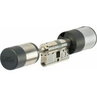
| Package contents | Lock with 2 keys, 5 adjustment shims, 3 screw covers, 1 strike plate, 1 double-sided adhesive, screws (4x) |
| Tools required for installation | Phillips screwdriver, drill, ruler, pencil, hammer, drill bits ∅ 2.5 and 6.5 mm |
| Main functions | Locking and unlocking with key, pivoting lever to lock/unlock, visual locking indicator (padlock closed/open) |
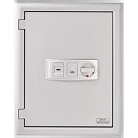
| Usage | Windows and French doors opening inward, made of wood or aluminum |
| Maintenance and cleaning | Clean with a soft, dry cloth. Avoid abrasive products. |
| Safety | VdS certified, tested according to DIN 18104-1, requires additional security per meter of window height |
| Spare parts and repairability | Set of shims, strike plate, screw covers available. Additional keys available from the manufacturer. |
| General information | Multilingual instructions available. Read carefully before installation. |
Frequently Asked Questions - WinSafe WS 11 Burg Wächter
User questions about WinSafe WS 11 Burg Wächter
0 question about this device. Answer the ones you know or ask your own.
Ask a new question about this device
Download the instructions for your Window lock in PDF format for free! Find your manual WinSafe WS 11 - Burg Wächter and take your electronic device back in hand. On this page are published all the documents necessary for the use of your device. WinSafe WS 11 by Burg Wächter.
USER MANUAL WinSafe WS 11 Burg Wächter
natural_image
White plastic door lock with key and keychain, no visible text or symbolsde Montage- und Bedienungsanleitung
en Assembly and User Manual
fr Instruction de montage et mode d'emploi
nl Montage- en gebruiksaanwijzing


Language
de Deutsch 3
en English 12
fr Français 21
nl Nederlands 30
it Download: www.burg.biz
text_image
Exploded view diagram of a wall-mounted device with numbered parts including screws, buttons, and key holdersnatural_image
Pure mechanical assembly diagram showing a bracket with mounting holes and a directional arrow (no text or symbols)natural_image
Technical line drawing of a door hinge with a handle and mounting bracket (no text or symbols)natural_image
Simple line drawing of two rectangular panels with arrows pointing to a small circle and a screw, no text or symbols present.natural_image
Technical line drawing of a door handle assembly with a screwdriver inserted (no text or symbols)natural_image
Technical line drawing of a mechanical assembly with multiple circular components and a central shaft (no text or symbols)text_image
1 P20028 W400271769 A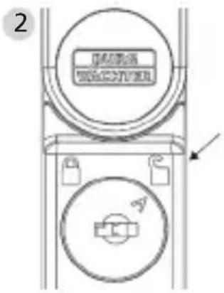
text_image
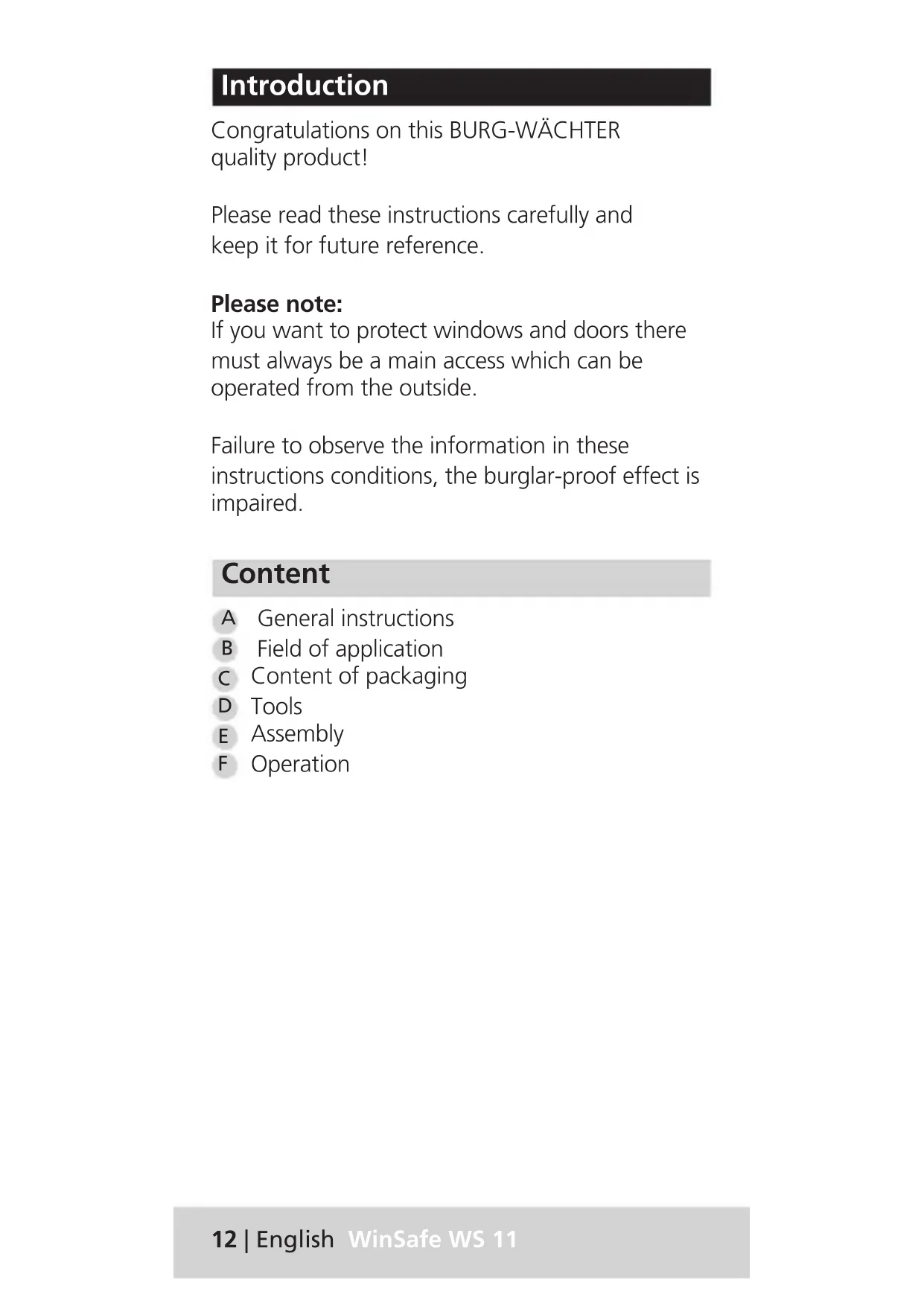
2 GACCO WACCO ACongratulations on this BURG-WÄCHTER quality product!
Please read these instructions carefully and keep it for future reference.
Please note:
If you want to protect windows and doors there must always be a main access which can be operated from the outside.
Failure to observe the information in these instructions conditions, the burglar-proof effect is impaired.
Content
A General instructions
B Field of application
c Content of packaging
D Tools
E Assembly
F Operation
A. General instructions
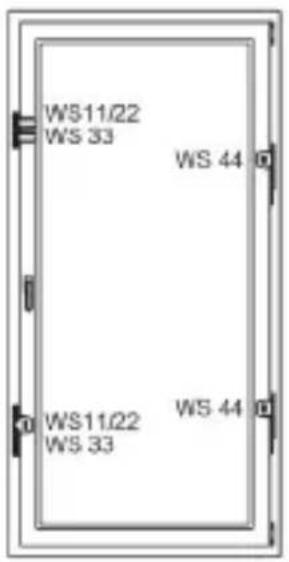
The window protection WS11 is approved by VdS 2536 and tested according to DIN 18104-1.
According to DIN 18104-1 at least one additional protection should be mounted on each side for every 1 m window height.
text_image
WS11/22 WS 33 WS 44 WS11/22 WS 33 WS 44On the operating side (handle side) at least one additional protection must be lockable.
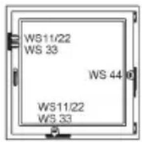
text_image
WS11/22 WS 33 WS 44 WS11/22 WS 33The borehole depths and screw lengths must be matched according to local conditions. Do not pierce the windows / French doors, eventually work with a drill stopper. When drilling do not damage any moving parts, seals or glass panes. The mounting screws should be tightened by hand to avoid overtighting.
For any possible injuries and / or damages caused by improper handling during assembly, the manufacturer accepts no liability.
As an additional security measure, the use of a BURG-WÄCHTER mounting anchor MA 99 DUO is recommended.
B. Field of application
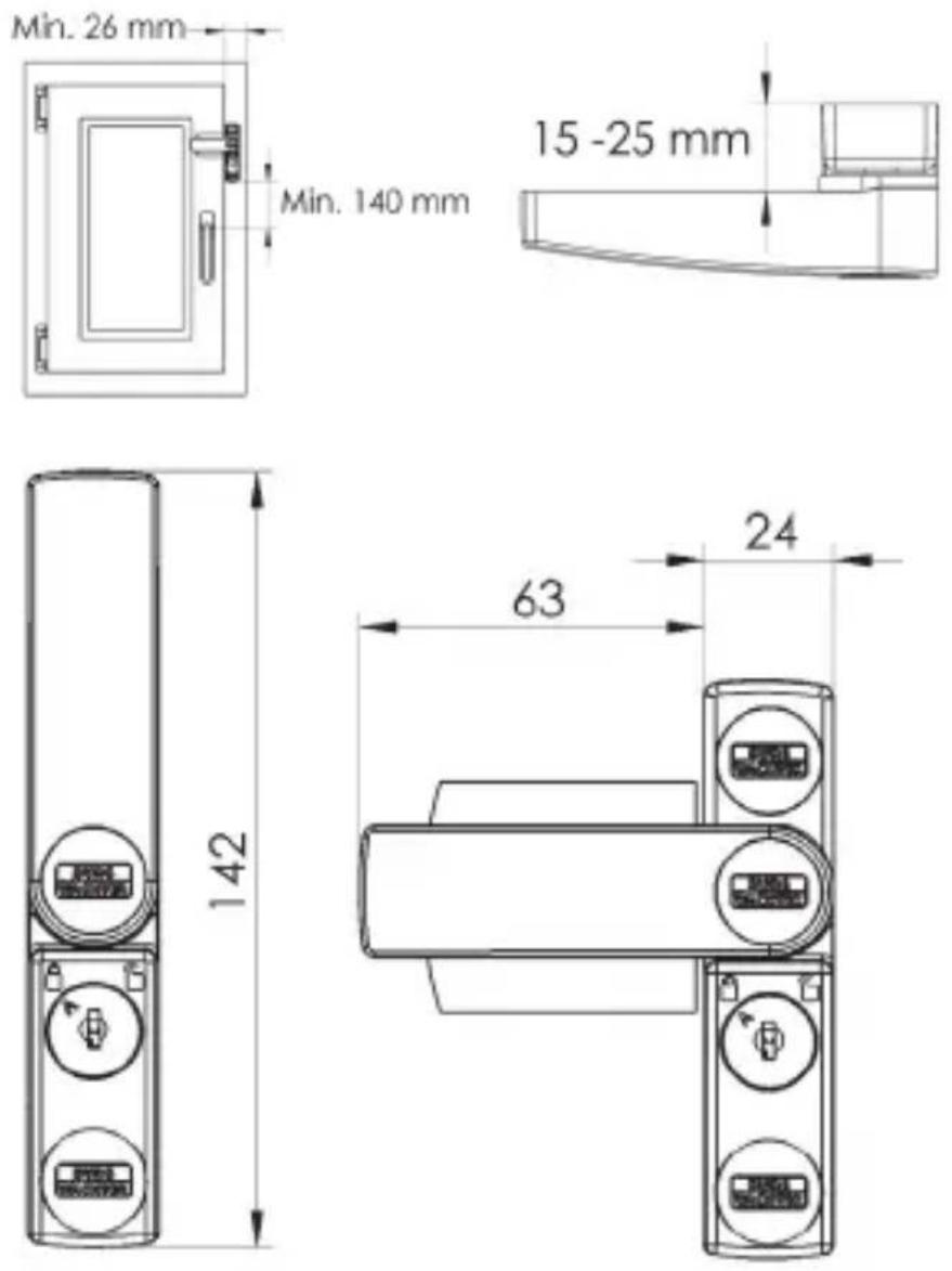
The WS 11 is mounted on the operating side (handle side) of the window or French door and is suitable for all standard, inward opening windows / French doors made of wood or aluminum.
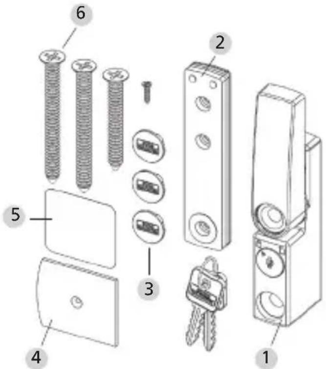
C. Content of packaging
text_image
Exploded view diagram of a wall-mounted device with numbered parts including screws, buttons, and key holders1 Window protection with 2 keys
2 Underlay for window protection 2 pieces 1 mm, 2 pieces 2 mm, 1 piece 4 mm
3 3 screw covers
4 1 casement plate
5 1 piece of double-sided adhesive pad
6 Countersunk head screws 1 pc. ∅ 8,0 x 60; 2 pcs. ∅ 8,0 x 80, 1 pc. ∅ 2,9 x 13
D. Tools
- Phillips screwdriver/drilling machine/scale/pencil/hammer
- Drill ∅ 2,5 / 6,5
- Saw / file / vice for shortening screws (if necessary)
E. Assembly
Before mounting please check the function of the window / window door. It must be possible to open and close properly. Please measure whether the on page 5 required dimensions are available for your window / French door.
text_image
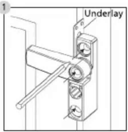
1 UnderlayOpen the window protection with the attached key and pull off the key. Turn the pivot lever to the side and hold the window protection on the window frame to the desired position.
Use a 1 mm thick underlay to create a distance from the window leaf and mark the 3 drilling positions with a pencil.
text_image
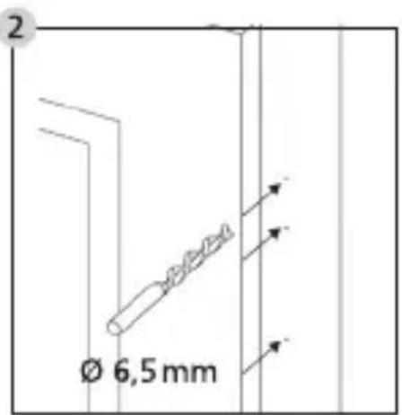
Ø 6,5 mmDeepen the markings lightly with e. g. a screw tip/hammer and drill the 3 holes with a ∅ 6,5 drill.
Do not drill through the window frame.
text_image
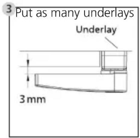
3 Put as many underlays Underlay 3 mmunder the window protection with the to create a distance of about 3 mm between the pivot lever and the casement.
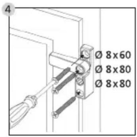
text_image
Ø 8x60 Ø 8x80 Ø 8x80Mount the window protection with the identified quantity of underlays and the accompanying screws.
Avoid overtighting of the screws.
natural_image
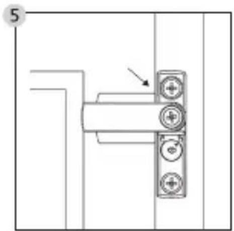
Pure mechanical assembly diagram without any text, numbers, or symbolsPosition the casement plate centrally beneath the pivot lever and flush with the window sash edge and hold it in place.
natural_image
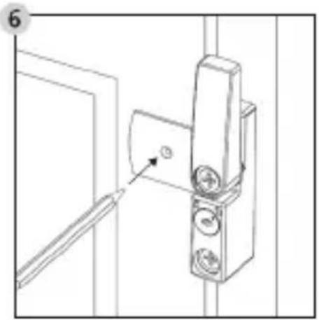
Technical line drawing of a door hinge mechanism with no visible text or symbolsTurn the pivot lever aside and mark the drilling position of the casement plate with a pencil.
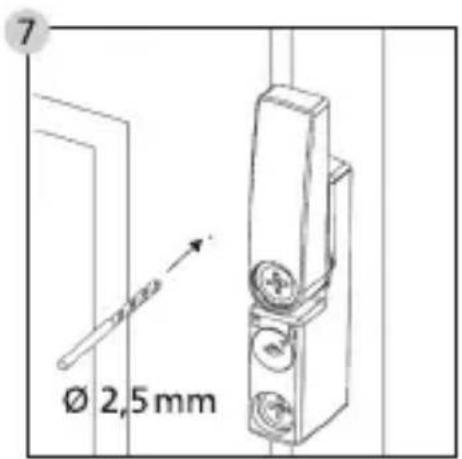
text_image
Ø 2,5 mmDeepen the marking lightly with e. g. a screw tip/hammer and drill the holes with a ∅ 2,5 drill.
When drilling do not damage any moving parts, seals or glass panes. Do not drill through the casement.
natural_image
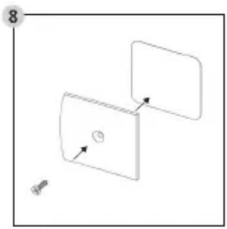
Simple 3D diagram showing two rectangular blocks with arrows indicating direction, one with a small circle and the other with a screw (no text or symbols)Stickdouble-sided adhesive pad a to the back of the cover plate. On the front the screw head must be visible. Pierce the adhesive pad with the countersunk screw
natural_image
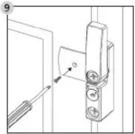
Technical line drawing of a door handle assembly with a screwdriver inserted (no text or symbols)Press the casement plate precisely on the casement and mount the screw ∅ 2,9 x 13.
Avoid overtighting of the screw.
natural_image
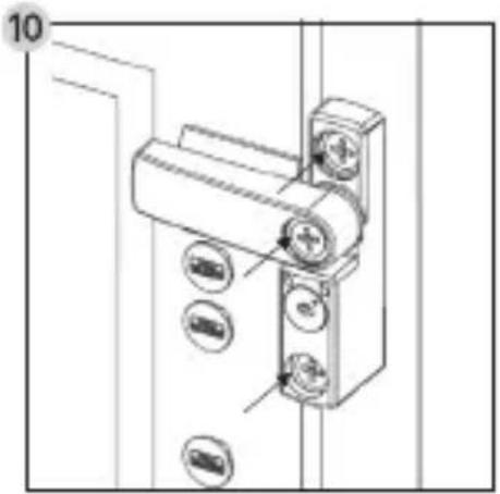
Technical line drawing of a mechanical assembly with multiple circular components and a central shaft (no text or symbols)Insert the covering caps into the screw holes.
Caution:
The caps can no longer be removed without damage!
F. Operation
text_image
1 ISO/ISO TENOCY1700 A M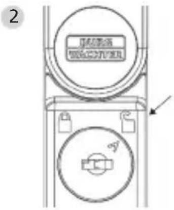
text_image
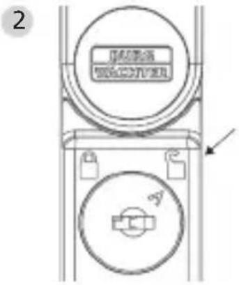
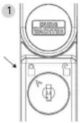
2 GARANT WACQUINER1 The arrow points to the closed lock: The window protection is locked
The pivot lever can be moved from the open position without a key into the locking position. Here it engages.
Unlocking and opening the window protection is only possible with the key.
A clockwise rotation of the key will unlock the window protection.
2 The arrow points to the opened lock: The window protection is unlocked
In this position the pivot lever can be easily moved in the latching positions.
The window protection is unlocked.
Introduction
text_image
Exploded view diagram of a wall-mounted device with numbered parts for identificationnatural_image
Pure mechanical assembly diagram showing a bracket with three circular components and an arrow indicating direction (no text or symbols)natural_image
Technical line drawing of a door hinge with a handle and mounting bracket (no text or symbols)natural_image
Simple line drawing of two rectangular panels with arrows pointing to a small circle and a screw, no text or symbols present.natural_image
Technical line drawing of a door handle assembly with a screwdriver inserted (no text or symbols)natural_image
Technical line drawing of a mechanical assembly with multiple circular components and a central shaft (no text or symbols)text_image
Exploded view diagram of a wall-mounted device with numbered parts including screws, buttons, and key holdersnatural_image
Pure mechanical assembly diagram without any text, numbers, or symbolsnatural_image
Technical line drawing of a door hinge with a handle and mounting bracket (no text or symbols)natural_image
Simple line drawing of two rectangular panels with arrows pointing to a small circle and a screw, no text or symbols present.natural_image
Technical line drawing of a door handle assembly with a screwdriver inserted (no text or symbols)natural_image
Technical line drawing of a mechanical assembly with multiple circular components and a central shaft (no text or symbols)text_image
1 E60028 W4C5V1700 A M