WinSafe WS 33 - Door/window sensor Burg Wächter - Free user manual and instructions
Find the device manual for free WinSafe WS 33 Burg Wächter in PDF.
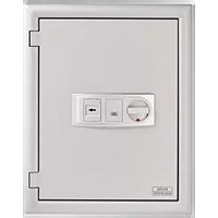
| Product Type | Door/window sensor (window security) |
| Brand | Burg Wächter |
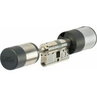
| Model | WinSafe WS 33 |
| Certification | VdS 2536, DIN 18104-1 |
| Dimensions (approx.) | 184 x 61.5 x 48 mm (L x H x D) |
| Weight (estimated) | Approximately 200 g |
| Power supply | None (mechanical) |
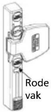
| Main functions | Mechanical locking, visual status indicator (red rectangle) |
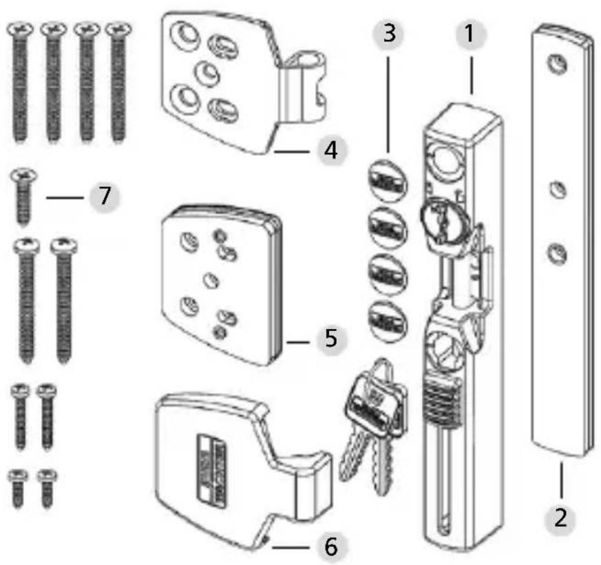
| Package contents | Window lock, strike plate, shims (1, 2, 4 mm), 4 screw covers, strike plate cover, flat head screws (4x4.8x50, 1x4.8x22), pan head screws (2x4.8x50, 2x3.5x25, 2x3.5x13) |
| Required tools | Phillips screwdriver, drill, ruler, pencil, hammer, drill bits ∅ 2.5 / 3.0 / 3.5 |
| Material | Steel and plastic |
| Mounting | Drill 3 holes in the frame (∅ 3.5), attach lock with shims, then mount strike plate (∅ 2.5 for wood, ∅ 3.0 for aluminum/PVC with metal insert) |
| Use | Locking by slider, unlocking by key (clockwise rotation), red indicator visible in open position |
| Maintenance | Clean with a soft dry cloth, do not use lubricants |
| Spare parts and repairability | Spare keys, screws, shims, and covers available |
| Safety | Do not force screws, do not drill completely through the frame, check proper operation after mounting |
Frequently Asked Questions - WinSafe WS 33 Burg Wächter
User questions about WinSafe WS 33 Burg Wächter
0 question about this device. Answer the ones you know or ask your own.
Ask a new question about this device
Download the instructions for your Door/window sensor in PDF format for free! Find your manual WinSafe WS 33 - Burg Wächter and take your electronic device back in hand. On this page are published all the documents necessary for the use of your device. WinSafe WS 33 by Burg Wächter.
USER MANUAL WinSafe WS 33 Burg Wächter
natural_image
White adjustable wrench tool with two key holders, no visible text or symbolsde Montage- und Bedienungsanleitung
en Assembly and User Manual
fr Instruction de montage et mode d'emploi
nl Montage- en gebruiksaanwijzing


Language
de Deutsch 3
en English 12
fr Français 21
nl Nederlands 30
it Download: www.burg.biz
es Descarga: www.burg.biz
pt Download: www.burg.biz
sv Download: www.burg.biz
no Download: www.burg.biz
dk Download: www.burg.biz
fi Ladattava tiedosto: www.burg.biz
el λήψη: www.burg.biz
tr indir: www.burg.biz
ro Descărcare: www.burg.biz
pl Pobieranie pliku: www.burg.biz
cs Stáhnout: www.burg.biz
hu Letölthető: www.burg.biz
s/ Download: www.burg.biz
sk Download: www.burg.biz
hr Download: www.burg.biz
ru загрузка: www.burg.biz
bg Download (зареди): www.burg.biz
et Download: www.burg.biz
www.burg.bizwww.burg
2 WinSafe WS 33
Einführung
text_image
Exploded view diagram of a smart home control panel with numbered parts for identificationtext_image
Technical diagram showing a door lock mechanism with labeled components and directional arrows indicating movement or assembly.natural_image
Technical line drawing of a door handle assembly with a tool inserted (no text or symbols)text_image
Ø 2,5/3,0natural_image
Technical line drawing of a door handle assembly with adjustment knobs and a lever (no text or symbols)natural_image
Technical line drawing of a mechanical device with no visible text or symbols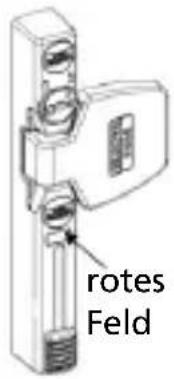
text_image
rotes FeldCongratulations on this BURG-WÄCHTER quality product!
Please read these instructions carefully and keep it for future reference.
Please note:
If you want to protect windows and doors there must always be a main access which can be operated from the outside.
Failure to observe the information in these instructions conditions, the burglar-proof effect is impaired.
Content
A General instructions
B Field of application
C Content of packaging
D Tools
E Assembly
F Operation
A. General instructions
The window protection WS33 is approved by VdS 2536 and tested according to DIN 18104-1.
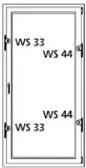
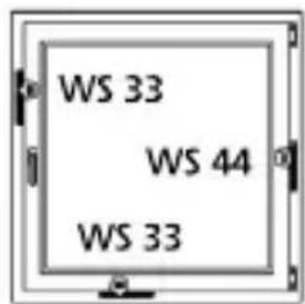
According to DIN 18104-1 at least one additional protection should be mounted on each side
text_image
WS 33 WS 44 WS 44 WS 33for every 1 m window height. On the operating side (handle side) at least one additional protection must be lockable.
text_image
WS 33 WS 44 WS 33The borehole depths and screw lengths must be matched according to local conditions. Do not pierce the windows / French doors, eventually work with a drill stopper. When drilling do not damage any moving parts, seals or glass panes. The mounting screws should be tightened by hand to avoid overtighting.
For any possible injuries and / or damages caused by improper handling during assembly, the manufacturer accepts no liability.
As an additional safety measure in case of plastic elements and possibly for aluminum and wooden elements, we recommend using the BURG-WÄCHTER mounting anchor MA 99 DUO.
B. Field of application
The WS 33 is mounted on the operating side (handle side) of the window or French door and is suitable for all standard, inward opening windows / French doors made of wood, aluminum or plastic with metal insert.
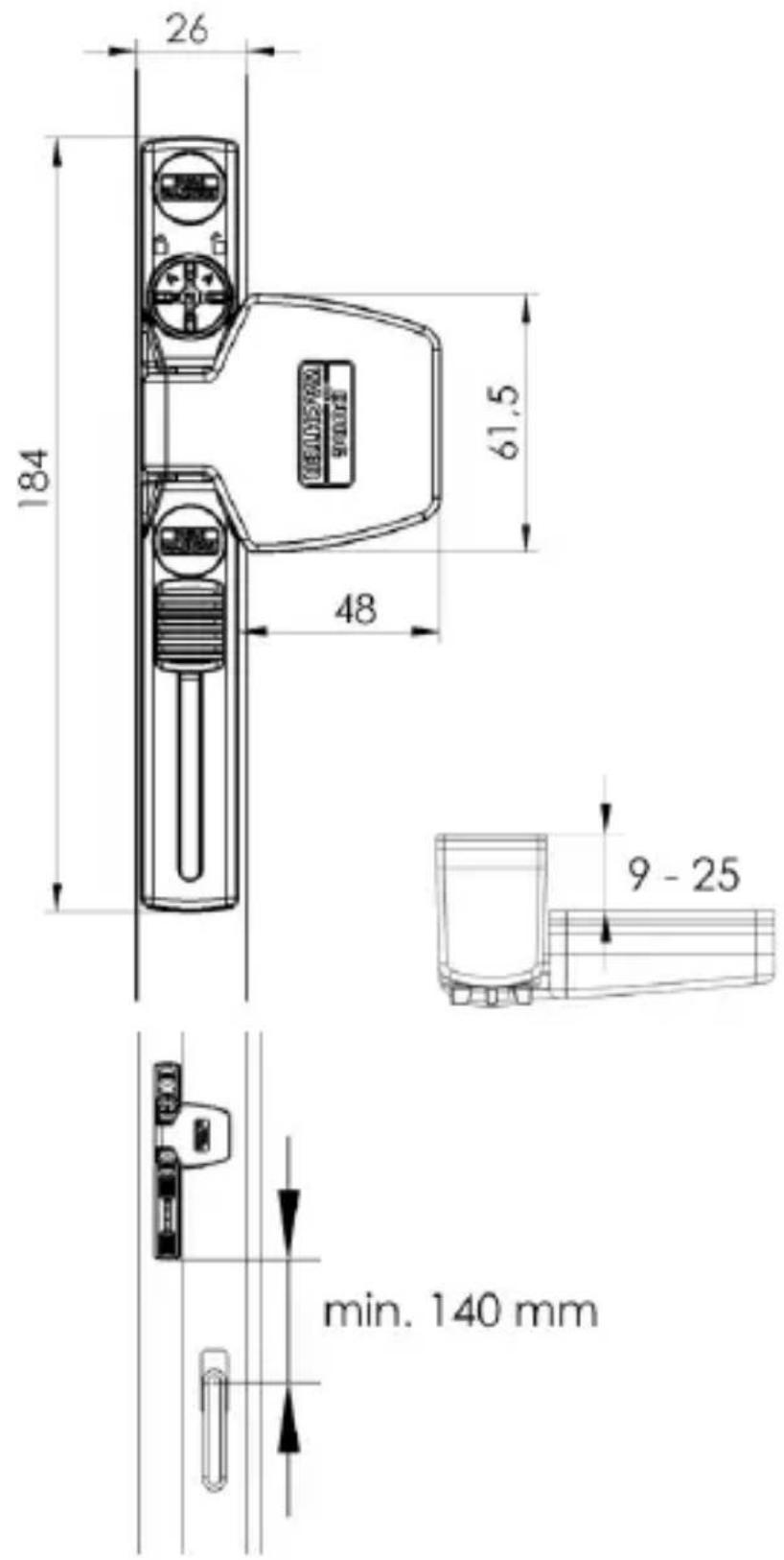
text_image
26 184 61.5 48 9 - 25 min. 140 mmC. Content of packaging
text_image
Exploded view diagram of a smart home control panel with numbered parts for identification1 Window protection
2 Underlay for window protection 1 mm, 2 mm, 4 mm
3 4 screw covers
4 Casement plate
5 Underlays for casement plate 1 piece 1 mm, 2 pieces 2 mm, 1 piece 4 mm
6 Casement plate covering
7 Countersunk screws
4 pcs. 4,8x50/1 pc. 4,8x22
rounded head screws
2 pcs. 4,8x50/2 pcs. 3,5x25/
2 pcs. 3,5x13
D. Tools
- Phillips screwdriver/drilling machine/scale/pencil/hammer
- Saw/file/vice for shortening screws (if necessary)
- Drill ∅ 2,5/3,0/3,5
E. Assembly
Before mounting please check the function of the window / French door. It must be possible to open and close properly. Please measure whether the on page 5 required dimensions are available for your window/French door.
text_image
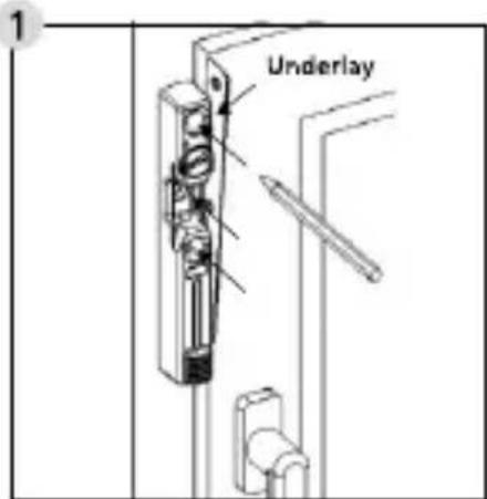
UnderlayOpen the window protection with the enclosed key and pull the key in this position. Hold the window protection to the desired position. Use a 2 mm thick underlay to create a distance
from the window leaf and mark the 3 drilling positions with a pencil.
text_image
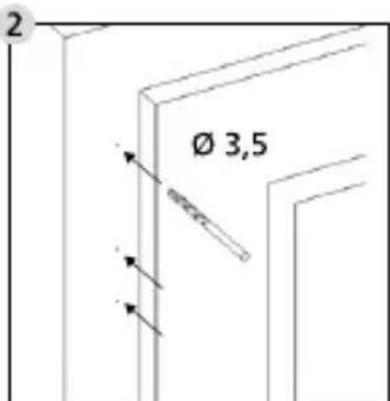
Ø 3,5Deepen the markings lightly with e. g. a screw tip/hammer and drill the 3 holes with a ∅ 3,5 drill.
Do not drill through the window frame.

text_image
Technical diagram showing a door lock mechanism with labeled components and directional arrows indicating movement or assembly.Insert the casement plate into the window protection and then slide the slider up. Hold the windows protection to the window and identify the necessary underlays. Open the window protection by
a slight clockwise rotation of the lock cylinder and remove the casement plate.
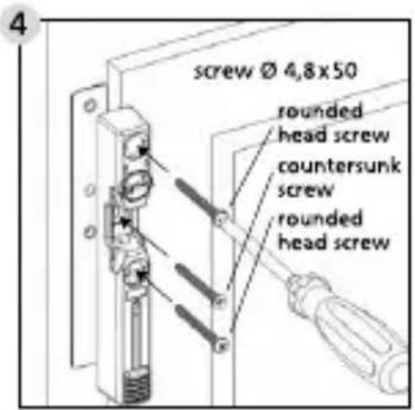
text_image
screw Ø 4,8x50 rounded head screw countersunk screw rounded head screwMount the window protection with the identified quantity of underlays and the accompanying screws.
Avoid overtighting of the screws.
natural_image
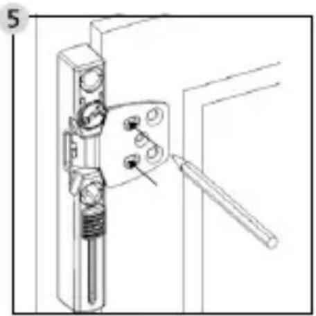
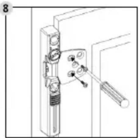
Technical line drawing of a door handle assembly with a tool inserted (no text or symbols)Insert the casement plate into the window protection, and then slide the slider up. If necessary put some underlays under the casement plate.
Open the window protection by a slight
clockwise rotation of the lock cylinder and remove the casement plate.
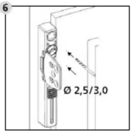
text_image
Ø 2,5/3,0Deepen the markings lightly with e. g. a screw tip/hammer and drill 2 holes with a ∅ 2,5 drill for wood or ∅ 3,0 for aluminum and plastic with metal insert. When drilling do not damage any
moving parts, seals or glass panes. Do not drill through the casement.
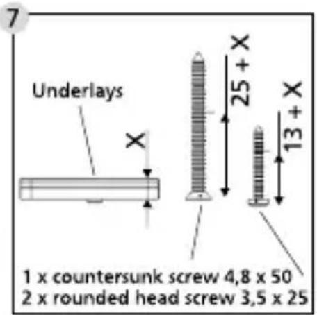
text_image
7 Underlays X 25 + X 13 + X 1 x countersunk screw 4,8 x 50 2 x rounded head screw 3,5 x 25If you are using underlays for the casement plate, please shorten the 2 rounded head screws 3,5x25 and 1 countersunk screw 4,8x50 accordingly.
natural_image
Technical line drawing of a door handle assembly with adjustment knobs and a wrench (no text or symbols)Fit the 2 rounded head screws ∅ 3,5 x 13 or the shortened screws.
Avoid overtighting of the screws.
Check the function of the window protection. The slide needs to
be moved easily. Readjust the casement plate if necessary. The window / French windows must be opened and closed properly.
text_image
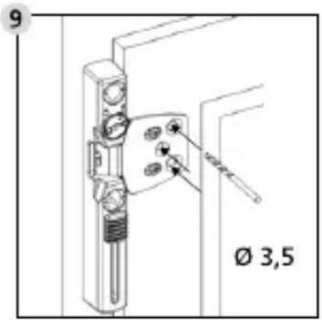
9 Ø 3,5Drill the 2 outer holes for the screws 4,8 x 50 and the middle hole for the screw 4,8 x 22 with a ∅ 3,5 mm drill.
When drilling do not damage any moving parts, seals or glass panes. Do not drill through the casement.
text_image
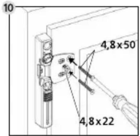
10 4,8×50 4,8×22Fit the casement plate with 2 countersunk screws 4,8 x 50 and 1 countersunk screw 4,8 x 22 or the shortened screw ∅ 4,8.
text_image
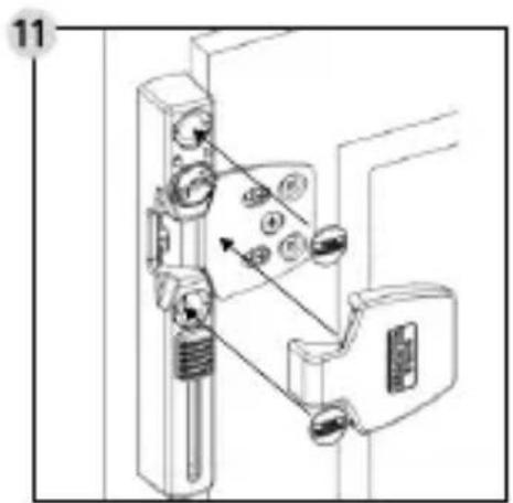
Technical diagram showing a mechanical assembly with labeled components and directional arrows indicating movement or force.Insert the covering caps on the casement plate and into the screw holes.
Caution: The caps can no longer be removed without damage!
F. Operation
1
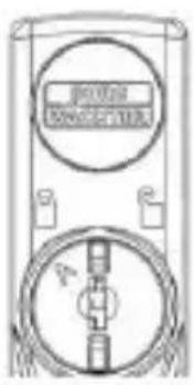
text_image
RIVER MACHINE2
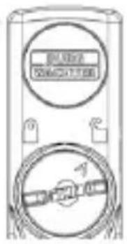
text_image
10V 250V 200mA 34.7Ω 100A 10V 250V 10V 250V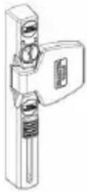
natural_image
Technical line drawing of a mechanical device with no visible text or symbols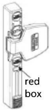
text_image
red box1 The arrow points to the closed lock: The window protection is locked.
An open window protection can be closed again with the slider. After that, the window protection is closed and locked. An unlocking and opening is only possible with the key. Through a clockwise rotation of the key, the window protection is unlocked and opened. The securing bolt will retract then.
2 The arrow points to the opened lock: The window protection is unlocked
In this position, the window protection can be closed with the slider. By a slight clockwise rotation of the lock cylinder, the window protection can be opened again.
The open state is signaled by a red box: Warning! The window protection is open.
Introduction
text_image
Exploded view diagram of a smart home control panel with numbered parts for identificationtext_image
Technical diagram showing a door lock mechanism with labeled components and directional arrows indicating movement or assembly.text_image
Vis 4,8x 50 Tête bombée Tête plate Tête bombéenatural_image
Technical line drawing of a door handle assembly with no visible text or symbolstext_image
6 Ø 2,5/3,0natural_image
Technical line drawing of a door handle assembly with adjustment knobs and a wrench (no text or symbols)natural_image
Technical line drawing of a mechanical device with no visible text or symbols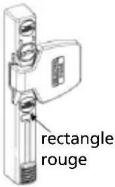
text_image
rectangle rougetext_image
Exploded view diagram of a smart home control panel with numbered parts for identificationtext_image
Technical diagram showing a door lock mechanism with labeled components and directional arrows indicating movement or assembly.natural_image
Technical line drawing of a door handle assembly with a tool inserted (no text or symbols)text_image
Ø 2,5/3,0natural_image
Technical line drawing of a door handle assembly with adjustment knobs and a wrench (no text or symbols)Monteer de 2 bolkop schroeven ∅ 3,5 x 13 of de ingekorte schroeven.
natural_image
Technical line drawing of a mechanical device with no visible text or symbols