
E 835 - Speaker HK AUDIO - Free user manual and instructions
Find the device manual for free E 835 HK AUDIO in PDF.
| Product type | Passive mid/high speaker |
| Brand | HK Audio |
| Model | E 835 |
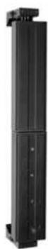
| Dimensions (W x H x D) | 11 x 74.5 x 12 cm |
| Weight | 4.5 kg |
| Nominal power | 300 W RMS at 8 Ω |
| Nominal impedance | 8 Ω |
| Frequency response (-10 dB) | 140 Hz - 20 kHz |
| Sensitivity (1 W @ 1 m) | 100 dB |
| Directivity | 70° horizontal |
| Speakers | 8 x 3.5" wideband |
| Connectivity | 1 input and 1 output E-Connect (bayonet) |
| Power | Passive (powered by active element via E-Connect or Speakon) |
| Recommended use | Professional sound reinforcement, ELEMENTS modular system |
| Mounting | Stackable, E-Connect bayonet mounting, compatible with tripod and coupling tubes |
| Cleaning | Dry cloth, do not use liquid |
| Usage conditions | Indoor, avoid humidity and rain |
| Safety | Do not open the enclosure, risk of electric shock and burns |
| Maintenance | Repair by qualified specialist only |
Frequently Asked Questions - E 835 HK AUDIO
User questions about E 835 HK AUDIO
0 question about this device. Answer the ones you know or ask your own.
Ask a new question about this device
Download the instructions for your Speaker in PDF format for free! Find your manual E 835 - HK AUDIO and take your electronic device back in hand. On this page are published all the documents necessary for the use of your device. E 835 by HK AUDIO.
USER MANUAL E 835 HK AUDIO
text_image
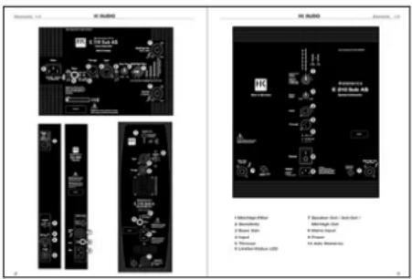
Leave enough space for proper ventilation! elements E 110 Sub AS System Subwoofer Made in Germany Mains 720-240 V~ 50-60 Hz 6 A rated current 8 10 Power 9 Through 10 Input 11 Bass Gain 12 Mid/High Filter 13 Select the number of mid/high units in ONE column Sub Out E 110 Sub 7 N4/N- 22.6 dB - N4/N- C - Tick CE Serial No. Caution: Risk of electric shock! Do not open! Refer servicing to qualified service personnel.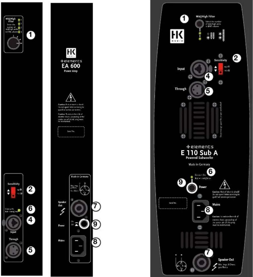
text_image
Mid/High Filter Select the number of high units in 50% volume 1 HK +elements EA 600 Power Amp Sensitivity 14 dB -10 dB Sensitivity Rad - High unit Input Through 2 6 4 5 Made in Germany Speaker Out Power Mains 7 9 8 1 Mid/High Filter Select the number of mid/high units in 50% volume HK AUDIO Sensitivity Eq. 41 10 dB Input Through 4 5 +elements E 110 Sub A Powered Subwoofer Made in Germany Grosser - On Rial - Limit/Error 9 Power Seal No. - - Mains Seals No. - - Speaker Out Min. Imp. & Chms. per Watts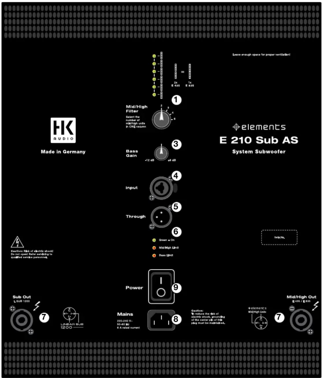
text_image
Leave enough space for proper ventilation! HK AUDIO Mid/High Filter Select the number of mid/high units in ONE column 1x E 435 E 835 elements E 210 Sub AS System Subwoofer Made in Germany Bass Gain +12 dB +6 dB Input Through Green On Mid/High Unit Bass Unit Sub Out L SUB 1200 7 Linear Sub 1200 Mains 220-240 V- 50-60 Hz 6 A rated current 9 Power Caution: To reduce the risk of electric shock, grounding of the center pin of this plug must be maintained. Mid/High Out E 435 / E 835 Sup|No. 71 Mid/High-Filter
2 Sensitivity
3 Bass Gain
4 Input
5 Through
6 Limiter-Status LED
7 Speaker Out / Sub Out /
Mid/High Out
8 Mains Input
9 Power
10 Auto Stand-by
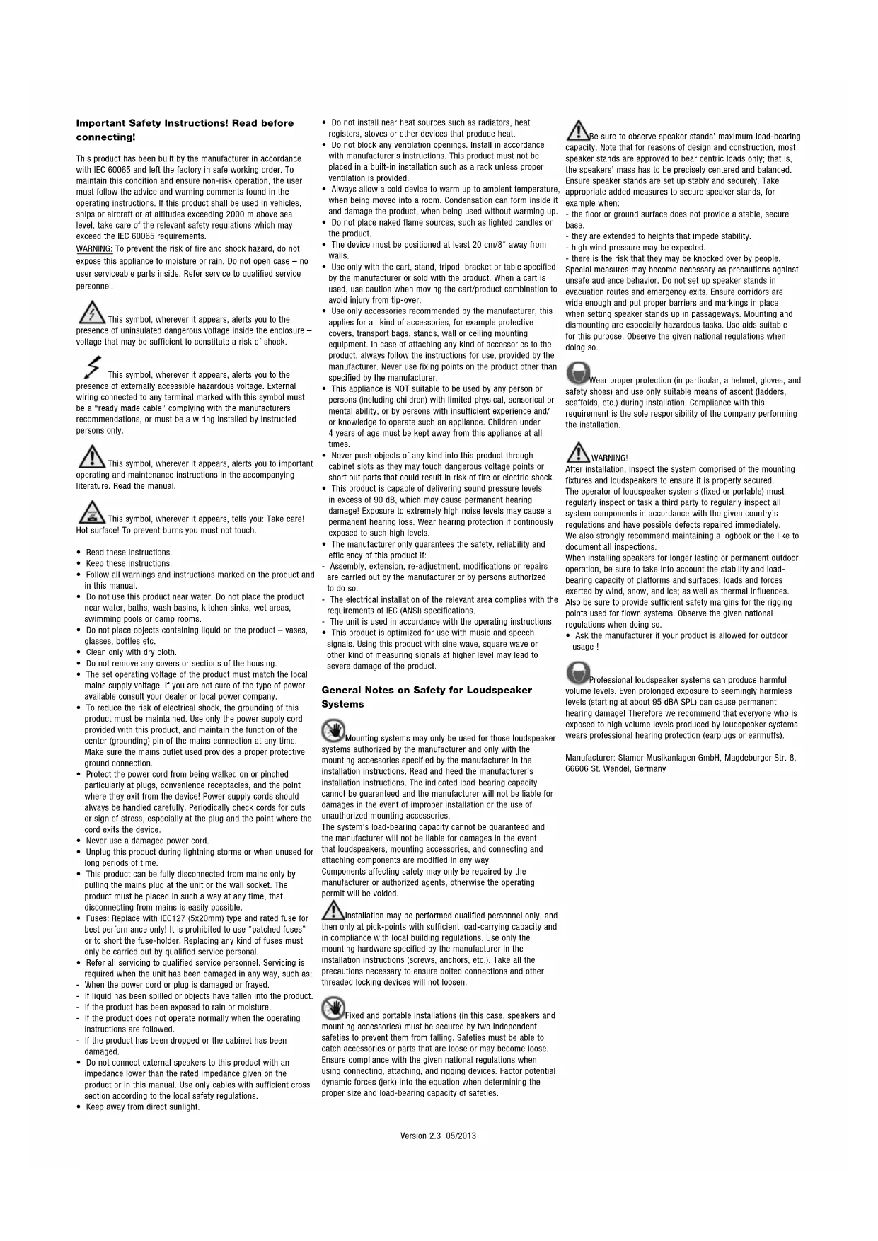
Important Safety Instructions! Read before connecting!
This product has been built by the manufacturer in accordance with IEC 60065 and left the factory in safe working order. To maintain this condition and ensure non-risk operation, the user must follow the advice and warning comments found in the operating instructions. If this product shall be used in vehicles, ships or aircraft or at altitudes exceeding 2000 m above sea level, take care of the relevant safety regulations which may exceed the IEC 60065 requirements.
WARNING: To prevent the risk of fire and shock hazard, do not expose this appliance to moisture or rain. Do not open case – no user serviceable parts inside. Refer service to qualified service personnel.

This symbol, wherever it appears, alerts you to the presence of uninsulated dangerous voltage inside the enclosure – voltage that may be sufficient to constitute a risk of shock.

This symbol, wherever it appears, alerts you to the presence of externally accessible hazardous voltage. External wiring connected to any terminal marked with this symbol must be a "ready made cable" complying with the manufacturers recommendations, or must be a wiring installed by instructed persons only.

This symbol, wherever it appears, alerts you to important operating and maintenance instructions in the accompanying literature. Read the manual.

This symbol, wherever it appears, tells you: Take care! Hot surface! To prevent burns you must not touch.
- Read these instructions.
- Keep these instructions.
- Follow all warnings and instructions marked on the product and in this manual.
- Do not use this product near water. Do not place the product near water, baths, wash basins, kitchen sinks, wet areas, swimming pools or damp rooms.
- Do not place objects containing liquid on the product – vases, glasses, bottles etc.
- Clean only with dry cloth.
- Do not remove any covers or sections of the housing.
- The set operating voltage of the product must match the local mains supply voltage. If you are not sure of the type of power available consult your dealer or local power company.
- To reduce the risk of electrical shock, the grounding of this product must be maintained. Use only the power supply cord provided with this product, and maintain the function of the center (grounding) pin of the mains connection at any time. Make sure the mains outlet used provides a proper protective ground connection.
- Protect the power cord from being walked on or pinched particularly at plugs, convenience receptacles, and the point where they exit from the device! Power supply cords should always be handled carefully. Periodically check cords for cuts or sign of stress, especially at the plug and the point where the cord exits the device.
- Never use a damaged power cord.
- Unplug this product during lightning storms or when unused for long periods of time.
- This product can be fully disconnected from mains only by pulling the mains plug at the unit or the wall socket. The product must be placed in such a way at any time, that disconnecting from mains is easily possible.
- Fuses: Replace with IEC127 (5x20mm) type and rated fuse for best performance only! It is prohibited to use "patched fuses" or to short the fuse-holder. Replacing any kind of fuses must only be carried out by qualified service personal.
- Refer all servicing to qualified service personnel. Servicing is required when the unit has been damaged in any way, such as: - When the power cord or plug is damaged or frayed.
- If liquid has been spilled or objects have fallen into the product.
- If the product has been exposed to rain or moisture.
- If the product does not operate normally when the operating instructions are followed.
- If the product has been dropped or the cabinet has been damaged.
- Do not connect external speakers to this product with an impedance lower than the rated impedance given on the product or in this manual. Use only cables with sufficient cross section according to the local safety regulations.
- Keep away from direct sunlight.
- Do not install near heat sources such as radiators, heat registers, stoves or other devices that produce heat.
- Do not block any ventilation openings. Install in accordance with manufacturer's instructions. This product must not be placed in a built-in installation such as a rack unless proper ventilation is provided.
- Always allow a cold device to warm up to ambient temperature, when being moved into a room. Condensation can form inside it and damage the product, when being used without warming up.
- Do not place naked flame sources, such as lighted candles on the product.
- The device must be positioned at least 20 cm/8" away from walls.
- Use only with the cart, stand, tripod, bracket or table specified by the manufacturer or sold with the product. When a cart is used, use caution when moving the cart/product combination to avoid injury from tip-over.
- Use only accessories recommended by the manufacturer, this applies for all kind of accessories, for example protective covers, transport bags, stands, wall or ceiling mounting equipment. In case of attaching any kind of accessories to the product, always follow the instructions for use, provided by the manufacturer. Never use fixing points on the product other than specified by the manufacturer.
- This appliance is NOT suitable to be used by any person or persons (including children) with limited physical, sensorical or mental ability, or by persons with insufficient experience and/or knowledge to operate such an appliance. Children under 4 years of age must be kept away from this appliance at all times.
- Never push objects of any kind into this product through cabinet slots as they may touch dangerous voltage points or short out parts that could result in risk of fire or electric shock.
- This product is capable of delivering sound pressure levels In excess of 90 dB, which may cause permanent hearing damage! Exposure to extremely high noise levels may cause a permanent hearing loss. Wear hearing protection if continuously exposed to such high levels.
- The manufacturer only guarantees the safety, reliability and efficiency of this product if:
- Assembly, extension, re-adjustment, modifications or repairs are carried out by the manufacturer or by persons authorized to do so.
- The electrical installation of the relevant area complies with the requirements of IEC (ANSI) specifications.
- The unit is used in accordance with the operating instructions.
• This product is optimized for use with music and speech
signals. Using this product with sine wave, square wave or other kind of measuring signals at higher level may lead to severe damage of the product.
General Notes on Safety for Loudspeaker Systems

Mounting systems may only be used for those loudspeaker systems authorized by the manufacturer and only with the mounting accessories specified by the manufacturer in the installation instructions. Read and heed the manufacturer's installation instructions. The indicated load-bearing capacity cannot be guaranteed and the manufacturer will not be liable for damages in the event of improper installation or the use of unauthorized mounting accessories.
The system's load-bearing capacity cannot be guaranteed and the manufacturer will not be liable for damages in the event that loudspeakers, mounting accessories, and connecting and attaching components are modified in any way.
Components affecting safety may only be repaired by the manufacturer or authorized agents, otherwise the operating permit will be voided.

Installation may be performed qualified personnel only, and then only at pick-points with sufficient load-carrying capacity and in compliance with local building regulations. Use only the mounting hardware specified by the manufacturer in the installation instructions (screws, anchors, etc.). Take all the precautions necessary to ensure bolted connections and other threaded locking devices will not loosen.

Fixed and portable installations (in this case, speakers and mounting accessories) must be secured by two independent safeties to prevent them from falling. Safeties must be able to catch accessories or parts that are loose or may become loose.
Ensure compliance with the given national regulations when using connecting, attaching, and rigging devices. Factor potential dynamic forces (jerk) into the equation when determining the proper size and load-bearing capacity of safeties.

Be sure to observe speaker stands' maximum load-bearing capacity. Note that for reasons of design and construction, most speaker stands are approved to bear centric loads only; that is, the speakers' mass has to be precisely centered and balanced. Ensure speaker stands are set up stably and securely. Take appropriate added measures to secure speaker stands, for example when:
- the floor or ground surface does not provide a stable, secure base.
- they are extended to heights that impede stability.
- high wind pressure may be expected.
- there is the risk that they may be knocked over by people. Special measures may become necessary as precautions against unsafe audience behavior. Do not set up speaker stands in evacuation routes and emergency exits. Ensure corridors are wide enough and put proper barriers and markings in place when setting speaker stands up in passageways. Mounting and dismounting are especially hazardous tasks. Use aids suitable for this purpose. Observe the given national regulations when doing so.

Wear proper protection (in particular, a helmet, gloves, and shoes) and use only suitable means of ascent (ladders,
ds, etc.) during installation. Compliance with this
requirement is the sole responsibility of the company performing the installation.

WARNING!
After installation, inspect the system comprised of the mounting fixtures and loudspeakers to ensure it is properly secured. The operator of loudspeaker systems (fixed or portable) must regularly inspect or task a third party to regularly inspect all system components in accordance with the given country's regulations and have possible defects repaired immediately. We also strongly recommend maintaining a logbook or the like to document all inspections.
When installing speakers for longer lasting or permanent outdoor operation, be sure to take into account the stability and load-bearing capacity of platforms and surfaces; loads and forces exerted by wind, snow, and ice; as well as thermal influences. Also be sure to provide sufficient safety margins for the rigging points used for flown systems. Observe the given national regulations when doing so.
- Ask the manufacturer if your product is allowed for outdoor usage!

Professional loudspeaker systems can produce harmful e levels. Even prolonged exposure to seemingly harmless (starting at about 95 dBA SPL) can cause permanent g damage! Therefore we recommend that everyone who is led to high volume levels produced by loudspeaker systems professional hearing protection (earplugs or earmuffs).
Manufacturer: Stamer Musikanlagen GmbH, Magdeburger Str. 8, 66606 St. Wendel, Germany

elements
Welcome to the HK Audio family!
Thank you for choosing a brand-name product made by our company. Rest assured, we engineered and built it with the greatest care so it will serve you well for many tomorrows to come.
Even if your experience with sound systems runs deep, some things about this product are sure to be new to you. This is why we ask that you do not set this manual aside without reading it first. Be sure to keep it in a safe place for later reference.
Here's wishing you the best sound at every occasion!
Your HK Audio team
Warranty
Register each ELEMENTS system component separately to extend your warranty to five years free of charge! Use the convenient online registration option at www.hkaudio.com.
If you are unable to register online, please fill out the enclosed warranty card, ensuring all information is legible and complete, and mail or fax it to us. The registration is only valid if the warranty registration card is filled out and returned to HK AUDIO® or the device is registered via Internet within 30 days of the date of purchase.
We are also interested in learning where and by whom our devices are used. This information will help us design future products. Your data are of course protected by German privacy laws. Thank you!
HK AUDIO
Technischer Service
Postfach 1509
66959 St. Wendel, Germany
Fax: +49 6851 905 100
text_image
Postfach 1509 66959 St. Wendel, Germany Fax: +49 6851 905 1001 The ELEMENTS principle
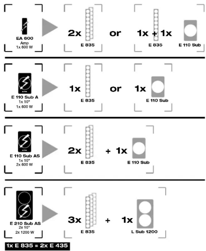
All ELEMENTS systems comprise active and passive components as well as customized accessories. Active components include an built-in amplifier with class D output stages, which power the passive components. No additional amplifiers are required. For special installation and voice applications, in which only passive loudspeakers are used, a separate EA 600 amp element is available.
The interconnecting of passive components and the connection to active components is cable-free for mid/high elements via E-connect, while passive bass elements are connected with a conventional Speakon NL4 cable. Active components are interconnected with an XLR microphone cable.
This means ELEMENTS system components can be combined with numerous different systems. The following diagram shows how many passive elements can be powered by a single active component.
text_image
EA 600 Amp 1x 600 W 2x E 835 or 1x + 1x E 835 E 110 Sub E 110 Sub A 1x 10" 1x 600 W 1x E 835 or 1x E 110 Sub E 110 Sub AS 1x 10" 2x 600 W 2x E 835 + 1x E 110 Sub E 210 Sub AS 2x 10" 2x 1200 W 3x E 835 + 1x L Sub 1200 1x E 835 = 2x E 435The following generally applies: You can reduce the number of passive components connected to an active element to suit your needs. The smallest ELEMENTS system accordingly consists of an E 110 Sub A and a E 435 mid/high element. Alternatively, even just an EA 600 amp element and an E 435 mid/high element for pure voice communication.
However, there is a limit to the number of passive components you can connect to an active element, even if the active element provides more power than required, depending on the combination! The key here is not the power, but the total impedance of the passive components connected to an active element. Since both E-connect and Speakon are connected as parallel ports, the total impedance declines with each additional passive element. If the impedance is too low, the electronics of the active elements may be damaged due to overheating.
2 Assembly and connection of elements
When assembling, please ensure the active system components are switched off, otherwise there is a risk of damage! Set the bass gain knob in the middle position with (0 dB / click center). Always start by assembling the complete system together with cabling and only then connect the active components. When disassembling: first switch off all active system components.
Caution: Be careful to ensure that the voltage data shown on the active components corresponds to the local mains voltage. Connecting to excess mains voltage may destroy the electronic equipment.
Bass elements
When using an individual bass element, always ensure it is placed on a firm and level surface. Depending on the operating mode and system configuration, E-connect allows bass elements to be installed on either the short or long sides, while four rubber feet at the base ensure vertical stability. When installing horizontally, one long side of the housing has two runners, while the opposite housing side has appropriate grooves, which allow multiple bass elements to be safely stacked on top of each other.
When using more than one bass element, it is advisable to start with the passive bass horizontally, and then stack the active bass on top, so that it can power the mid/high element via E-connect.
Mid/high elements
E-connect facilitates the swift and secure signal connection of the element, by establishing the electrical and mechanical connection to the nearest mid/high element, bass, spacer stem, or the foot. The durable bayonet system ensures a safe mechanical connection when installing simply by clicking the components together and also transmits the loudspeaker signal.
Connecting the elements
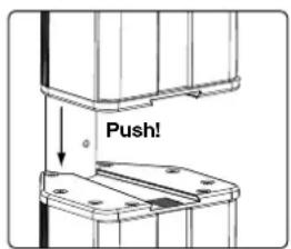
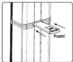
text_image
Push!Position the components to be connected such that the respective tube joints are over each other. To fix the individual components together securely, insert the tube joint of the upper element completely into the adjusting sleeve of the lower element. Be careful to ensure that the release button snaps into the relevant adjusting hole.
Uncoupling a connection
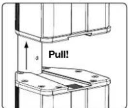
text_image
Pull!To disconnect components, press and hold the release button in the tube joint and then pull apart the components.
The correct height
Since line-array systems such as ELEMENTS provide vertical sound emission, when installing, always ensure that the central point of a line of one or multiple mid/high elements is continually adjusted to the head height of the listener.
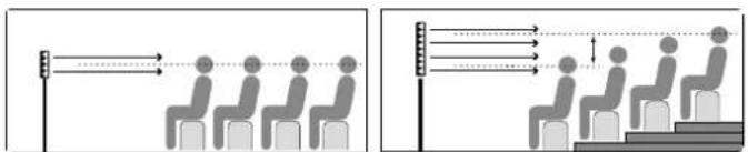
text_image
Diagram showing two scenarios of seating arrangement with directional arrows and human figures, likely illustrating seating or movement patterns.To adapt the height of a line, infinitely adjustable spacer stems, which can be locked using a twist-off cap, are optionally available in two different lengths:
EP 1: 95 - 160 cm
EP 2: 40 - 60.5 cm
The correct angle
To achieve perfect emitting properties, all connected components must emit sound at the same angle. The ELEMENTS locking wedge feature lets you lock the mid/high element under each other or on a bass, whereupon twisting is no longer possible.
text_image
Push!The locking wedge is simply clicked into the special shaft provided and released simply by applying slight pressure to the central plate. Note: for older ELEMENTS system components without locking wedges, retrofit kits are available - please connect your ELEMENTS dealer.
Installation pointers
When installing, always be careful to ensure a horizontal and firm surface! To avoid any risk of overturning, the following installation information for ELEMENTS configurations should be followed to the letter.
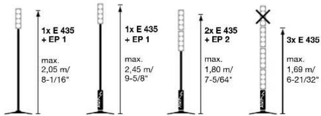
Combinations with foot EF 45 connected to spacer stems EP 1 / EP 2 and the mid/high element E 435 (or E 835)
Be careful when installing an ELEMENTS system with the foot EF 45 to ensure the extended feet are always pushed out completely and fixed by locking screws. The following specified maximum heights must not be exceeded. Never connect together two spacer stems!
text_image
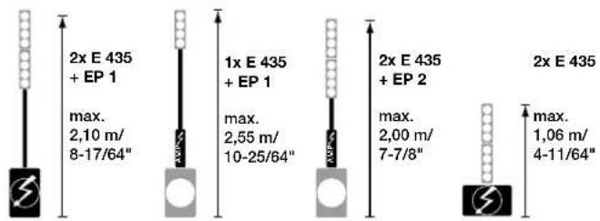
1x E 435 + EP 1 max. 2,05 m/ 8-1/16" 1x E 435 + EP 1 max. 2,45 m/ 9-5/8" 2x E 435 + EP 2 max. 1,80 m/ 7-5/64" 3x E 435 max. 1,69 m/ 6-21/32"Combinations with bass element E 110 Sub A / AS connected to spacer stems EP 1 or EP 2 and the mid/high element E 435 / E 835
The following specified maximum heights must not be exceeded. Never connect together two spacer stems!
text_image
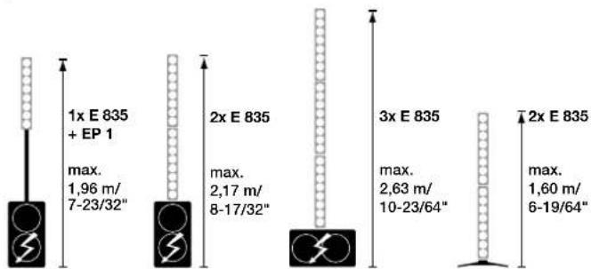
2x E 435 + EP 1 max. 2,10 m/ 8-17/64" 1x E 435 + EP 1 max. 2,55 m/ 10-25/64" 2x E 435 + EP 2 max. 2,00 m/ 7-7/8" 2x E 435 max. 1,06 m/ 4-11/64"Combinations with bass element E 210 Sub AS connected to the spacer stem EP 2 and the mid/high element E 835
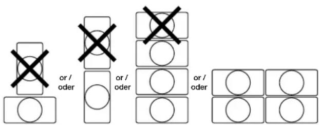
The following specified maximum heights must not be exceeded. Never connect together two spacer stems! When operating three E 835 elements, it is important to ensure the bass is only used in a horizontal position.
text_image
1x E 835 + EP 1 max. 1,96 m/ 7-23/32" 2x E 835 max. 2,17 m/ 8-17/32" 3x E 835 max. 2,63 m/ 10-23/64" 2x E 835 max. 1,60 m/ 6-19/64"Installation of the bass elements (E 110 Sub A / AS, E 110 Sub, E 210 Sub AS, L Sub 1200)
When used individually, the bass element can be operated in either a vertical and horizontal position. However, bass elements can only be stacked in a horizontal position! No more than three bass elements should be stacked horizontally on top of each other!
3 Control elements of the active component
text_image
PC BLDMS PC BLDMS 1. 10kV/10kV 2. 5kV/10kV 3. 10kV/10kV 4. 15kV/10kV 5. 20kV/10kV 6. 25kV/10kV 7. 30kV/10kV 8. 35kV/10kV 9. 40kV/10kV 10. 45kV/10kV 11. 50kV/10kV 12. 55kV/10kV 13. 60kV/10kV 14. 65kV/10kV 15. 70kV/10kV 16. 75kV/10kV 17. 80kV/10kV 18. 85kV/10kV 19. 90kV/10kV 20. 95kV/10kV 21. 100kV/10kV 22. 105kV/10kV 23. 110kV/10kV 24. 115kV/10kV 25. 120kV/10kV 26. 125kV/10kV 27. 130kV/10kV 28. 135kV/10kV 29. 140kV/10kV 30. 145kV/10kV 31. 150kV/10kV 32. 155kV/10kV 33. 160kV/10kV 34. 165kV/10kV 35. 170kV/10kV 36. 175kV/10kV 37. 180kV/10kV 38. 185kV/10kV 39. 190kV/10kV 40. 195kV/10kV 41. 200kV/10kV 42. 205kV/10kV 43. 210kV/10kV 44. 215kV/10kV 45. 220kV/10kV 46. 225kV/10kV 47. 230kV/10kV 48. 235kV/10kV 49. 240kV/10kV 50. 245kV/10kV 51. 250kV/10kV 52. 255kV/10kV 53. 260kV/10kV 54. 265kV/10kV 55. 270kV/10kV 56. 275kV/10kV 57. 280kV/10kV 58. 285kV/10kV 59. 290kV/10kV 60. 295kV/10kV 61. 300kV/10kV 62. 305kV/10kV 63. 310kV/10kV 64. 315kV/10kV 65. 320kV/10kV 66. 325kV/10kV 67. 330kV/10kV 68. 335kV/10kV 69. 340kV/10kV 70. 345kV/10kV 71. 350kV/10kV 72. 355kV/10kV 73. 360kV/10kV 74. 365kV/10kV 75. 370kV/10kV 76. 375kV/10kV 77. 380kV/10kV 78. 385kV/10kV 79. 390kV/10kV 80. 395kV/10kV 81. 400kV/10kV 82. 405kV/10kV 83. 410kV/10kV 84. 415kV/10kV 85. 420kV/10kV 86. 425kV/10kV 87. 430kV/10kV 88. 435kV/10kV 89. 440kV/10kV 90. 445kV/10kV 91. 450kV/10kV 92. 455kV/10kV 93. 460kV/10kV 94. 465kV/10kV 95. 470kV/10kV 96. 475kV/10kV 97. 480kV/10kV 98. 485kV/10kV 99. 490kV/10kV 99. 495kV/10KAll active elements provide similar features – a diagram of the control elements is included on page 2/3:
1 Mid/high fi Iter with LED indicator
The mid/high filter is used to adjust the frequency response of the active element electronics to the frequency response of the connected mid/high element. This manual configuration is crucial, since the output stage cannot automatically detect how many mid/high elements are connected. However, when connecting a passive bass, no adaptation is required.
Caution: The figures specified on the filter switch always apply to the mid/high element E 435 (four tweeters). When using the mid/high element E 835 (eight tweeters), this should always be counted as two E 435s.
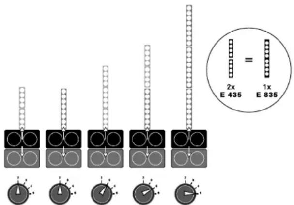
text_image
2x E 435 1x E 835Example: mid/high filter of the E 210 Sub AS
2 Sensitivity switch (except E 210 Sub AS)
This switch allows you to adjust the sensitivity of the input stage to the output level control of your mixer. When using a professional mixer with symmetrical outputs, the adaptation should be set to +4 dB, which allows you to optimize use of the mixer faders and avoid over-modulation. If a mixer with low output level control is used (asymmetrical communication jack), select the -10 dB configuration.
The double-bass E 210 Sub AS does not include any adaptation switch, since it is designed for professional applications with symmetrical signals.
Important note: If the system includes multiple output stages (active elements), for example in a stereo set-up, it is important to ensure that the same sensitivity configuration is selected for all output stages.
3 Bass Gain (only for E 110 Sub AS, E 210 Sub AS)
This knob adjusts the volume of the bass element but not the connected mid/high elements. It can be configured within the range -12 to +6 dB, and we recommend starting with the 0 dB setting.
4 Input
This combination socket can accommodate both XLR as well as jack plugs. Connect symmetrical signals with an XLR microphone cable or with stereo jack plugs to this socket. Asymmetrical signals can be connected with a mono jack plug.
5 Through
Parallel XLR output to forward the input signal (input) to additional active elements.
6 Limiter status LED
The two-color LED shows the status of the input signal.
Green = ready for operation
Red = Signal is over-amplified, whereupon the built-in RMS limiter is triggered (to protect the electronics against over-amplification)
Caution: This device is not a clip LED. It is normal for the LED to light up in red occasionally, since this simply shows that the RMS limiter is operational. If the signal LED remains red during signal peaks, check the output level control of the signal source and the setting of the sensitivity switch.
The E 210 Sub AS includes a separate power LED, which lights up green, if the power switch is set to ON and the power is turned on.
7 Speaker Out (E 110 Sub A, EA 600)
Sub Out / Mid/High Out (E 110 Sub AS, E 210 Sub AS)
The Speakon outputs on the E 110 Sub A and EA 600 are used to connect the passive bass E 110 Sub and to forward signals to mid/high elements via the optional accessory foot EF 45. For this purpose, use the conventional Speakon NL4 cable (NL4 = four cores: 1+, 1-, 2+, 2-)
The basses with two output stages E 110 Sub AS and E 210 Sub AS are equipped with separate outputs for passive basses and mid/high elements. The Sub Out socket of the E 110 Sub AS can only be used with the E 110 Sub, while the socket of the E 210 Sub AS may only be used to connect a passive L Sub 1200.
Speakon cables are connected in a clockwise direction by pushing in and turning the locking mechanism, turning counter-clockwise releases the connection.
Caution: The mid/high output is parallel-connected to E-connect, and may only be used when E-connect is not in operation.
Caution: If external devices are connected to the NL4 output, this and the ELEMENTS components may be destroyed.
8 Mains Input
Connect this connector socket using a low-power connection cable (included with delivery) with the mains socket.
Note: The active elements include a lockable V-Lock mains input socket. Combined with a lockable connection cable („Volex“ or structurally identical, optional available) the power cable can be cut off thus preventing any risk of inadvertent reactivation.
9 Power switch
When switching on, the signal LED lights up for around 5 seconds in red and then switches to green to indicate it is ready for operation. The fan is temperature-controlled and runs throughout the system check.
10 Auto Stand-by (only E 110 Sub AS)
The E 110 Sub AS also includes an auto standby function, which is switched on and off via an auto standby switch. When switched to ON, the output stage will automatically revert to sleep mode if no signal is connected for 180 minutes. From a level of -68 dB (1 kHz), the E 110 Sub AS resumes operation. Auto standby to OFF deactivates this function and the subwoofer remains permanently ON.
4 Accessories
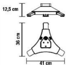
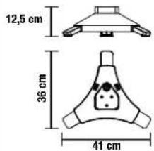
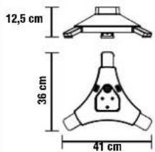
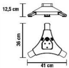
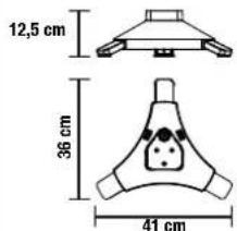
EF 45 Base
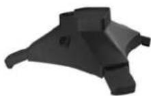
The foot acts as the base for the top speakers, the amp module or the spacer stem. The extendable base extensions ensure the attached elements remain safely and securely in place.
• Stable foot with minimal footprint
• built-in E-connect-signal connection
• 2x parallel NL4 connection
• 7.7 kg
• available as option: The perfect bag for the EF 45 foot, which you can carry over your shoulder.

EF 45 for transportation EF 45 in use
text_image
12,5 cm 36 cm 41 cm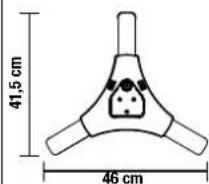
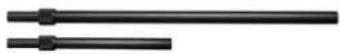
EP 1/EP 2 Speaker Poles
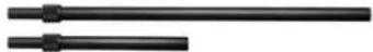
In confined spaces, these devices facilitate easy and swift installation. They are infinitely variable and via E-connect, provide cable-free signal feed for the attached top speakers.
• Anodized aluminum with large mounting screw
• Built-in E-connect-signal connection
• Weight EP 1: 0.8 kg; EP 2: 0.5 kg
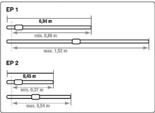
text_image
EP 1 0,94 m min. 0,86 m max. 1,52 m EP 2 0,45 m min. 0,37 m max. 0,54 mSoft Bag (E 435, E 835, EA 600)

natural_image
Two black electronic devices with open lids, one open and one closed, both without visible text or symbols.The padded case can accommodate four E 435 or two E 835 mid/high elements or four EA 600 amp elements. In addition, a spacer stem can also be fitted.
Subwoofer Cover


Subwoofers are frequently not moved around with kid gloves. With this in mind, this cover was double-cushioned to effectively protect active and passive subs against damage in transit.
Also available for ELEMENTS' permanent installation:
Install Kit E 435 • Install Kit E 435 A (active)
The ELEMENTS Install Kit consists of E 435 and EA 600 units that have been modified for wall mounting. Up to six components may be combined. The elements can be positioned horizontally through 180 degrees on the mounting brackets and be fixed swiftly and hassle-free using the two socket head screws provided.
Use speaker cords equipped with mono 1/4" (6.3 mm) jack plugs. Visit www.hkaudio.com to learn more about this.
5 Technical data
| E 835 E 435 E 210 Sub AS E 110 Sub AS E 110 Sub A L Sub 1200 E 110 Sub EA 600 | ||||||||
| Power handling, nominal | 300 W RMS @ 8 Ω | 150 W RMS @ 16 Ω | - | 1200 W RMS @ 8 Ω | 250 W RMS @ 10 Ω | - | ||
| Continuous power per amp | -- 1200 W Class-D @ | 4 Ω (Subs) / 1200 Watt Class-D @ 4 Ω (Mid/High) | 600 W Class-D @ 4 Ω (Subs) / 600 Watt Class-D @ 4 Ω (Mid/High) | 600 W Class-D @ 4 Ω | -- 600 W Class-D | @ 4 Ω | ||
| Frequency response -10 dB | 140 Hz - 20 kHz, via active system filter | 140 Hz - 20 kHz, via active system filter | 38 Hz - 150 Hz via active system x-over | 45 Hz - 150 Hz via active system x-over | 45 Hz - 150 Hz via active system x-over | 38 Hz - 150 Hz via active system x-over | 45 Hz - 150 Hz via active system x-over | - |
| Nominal impedance | 8 Ω | 16 Ω | 8 Ω | 10 Ω | 10 Ω | 8 Ω | 10 Ω | - |
| Axial sensitivity 1 W @ 1 m * | 100 dB | 97 dB | - | - | - | - | - | - |
| Active protective circuits | - | - | RMS limiter, subsonic filter; DC, load, & thermal (temp.- controlled fan) | RMS limiter, subsonic filter; DC, load, & thermal (temp.- controlled fan) | RMS limiter, subsonic filter; DC, load, & thermal (temp.- controlled fan) | - | - | RMS limiter, subsonic filter; DC, load, & thermal (temp.- controlled fan) |
| Input sensitivity | - | - | +4 dBu | (switchable) +4 dBu / -10 dBu | +4 dBu / -10 dBu (switchable) | -- +4 dBu / -10 dBu | (switchable) | |
| Connectors | 1 x E-Connect In 1 x E-Connect Out | 1 x E-Connect In 1 x E-Connect Out | 1 x XLR-Combo In 1 x XLR-Through 2 x Speakon Out (1 x Sub + 1 x Mid-High) 2 x E-Connect Out | 1 x XLR-Combo In 1 x XLR-Through 2 x Speakon Out (1 x Sub + 1 x Mid-High) 2 x E-Connect Out | 1 x XLR-Combo In 1 x XLR-Through 1 x Speakon Parallel Out 2 x E-Connect Out | 1 x Speakon In 1 x Speakon Out | 1 x Speakon In 1 x Speakon Out 1 x E-Connect Out | 1 x XLR-Combo In 1 x XLR-Through 1 x Speakon Parallel Out 1 x E-Connect Out |
| Speakers | 8 x 3.5" broadband | 4 x 3.5" broadband | - | - | - | - | - | |
| Woofers | -- 2 x 10"(2.,5" voice | coil) | 1 x 10" (2" voice coil) | 1 x 10" (2" voice coil) | 2 x 10" (2.5" voice coil) | 1 x 10" (2" voice coil) | - | |
| Directivity | 70° horizontal | 70° horizontal | - | - | - | - | - | - |
| Corner frequency, passive x-over | 140 Hz, 12 dB/oct. | 140 Hz, 12 dB/oct. | - - - - - | |||||
| Pole mount | -- 2 x E-Connect | coupler | 2 x E-Connect coupler | 2 x E-Connect coupler | 2 x M20 | 1 x E-Connect coupler | - | |
| Optional accessories | -- 100 mm Blue | Wheels | - | - | - | - | - | |
| Dimensions (W x H x D) | 11 x 74.5 x 12 cm (excl. E-Connect sleeves) | 11 x 38 x 12 cm (excl. E-Connect sleeves) | 38 x 66,8 x 56 cm | 30 x 48 x 46 cm | 30 x 48 x 46 cm | 38 x 66,8 x 56 cm | 30 x 48 x 46 cm | 11 x 38 x 12 cm (excl. E-Connect sleeves) |
| Weight | 4.5 kg | 2.35 kg | 32 kg | 18.5 kg | 19 kg | 29 kg | 16.5 kg | 2.75 kg |
text_image
Diagram illustrating seating arrangement and seating arrangement with directional arrows and human figurestext_image
Scanned document page showing two panels: one with a 3D layout diagram and another with a 2D layout diagram, both containing labeled sections and descriptive text blocks.EF 45 for transportation EF 45 in use
text_image
12,5 cm 36 cm 41 cm
text_image
41,5 cm 46 cmEP 1/EP 2 Distanzstangen

natural_image
Two black medical or laboratory devices: one open with a cylindrical tube, the other closed with a labeled case (no visible text or symbols on the device itself)text_image
Diagram illustrating seating arrangement and seating arrangement with directional arrows and human figurestext_image
Scanned document page showing two panels: one with a 3D layout diagram and another with a 2D layout diagram, both containing labeled sections and descriptive text blocks.EF 45 Base (Trépied)

EF 45 for transportation EF 45 in use
text_image
12,5 cm 36 cm 41 cm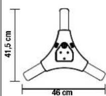
text_image
41,5 cm 46 cm
Tubes de couplage EP 1 / EP 2
natural_image
Two black rectangular devices: one open with a handle, the other closed with a labeled case (no visible text or symbols on the device itself)text_image
Diagram illustrating human seating arrangement and seating arrangement with directional arrows and distance markerstext_image
Technical diagram of a device layout with labeled components and technical specifications in Chinese.EF 45 for transportation EF 45 in use
text_image
12,5 cm 36 cm 41 cm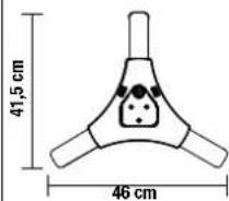
natural_image
Two black medical or laboratory devices: one open with a handle, the other closed with a labeled case (no visible text or symbols on the device itself)natural_image
Diagram showing three seated human figures with arrows indicating light or direction, no text or symbols present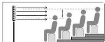
text_image
Diagram illustrating human behavior with labeled arrows and seating positions, possibly depicting a vision or presentation setup.text_image
Technical diagram of a mobile phone interface with labeled components and descriptions in ChineseEF 45 for transportation EF 45 in use
text_image
12,5 cm 36 cm 41 cm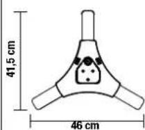
EP 1/EP 2 Barras distanciadoras
