ZoneAire ZCP10SA - Air Conditioning Friedrich - Free user manual and instructions
Find the device manual for free ZoneAire ZCP10SA Friedrich in PDF.

User questions about ZoneAire ZCP10SA Friedrich
0 question about this device. Answer the ones you know or ask your own.
Ask a new question about this device
Download the instructions for your Air Conditioning in PDF format for free! Find your manual ZoneAire ZCP10SA - Friedrich and take your electronic device back in hand. On this page are published all the documents necessary for the use of your device. ZoneAire ZCP10SA by Friedrich.
USER MANUAL ZoneAire ZCP10SA Friedrich
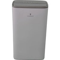
Portable Air Conditioner with Heat
OWNER'S MANUAL
natural_image
White industrial air conditioner unit with ventilation grille and brand logo (no visible text or symbols on device body)TABLE OF CONTENTS
Important Safety Guidelines ____ 2
Introduction 3
Unpacking Instructions & Contents ____ 4
Parts 5
Display Functions ____ 6
Remote Control Functions ____ 9
Drain Pipe 12
Maintenance & Cleaning 13
Installation 14
Troubleshooting ____ 16
IMPORTANT SAFETY GUIDELINES
| WARNING | |
| Electrical Shock Hazard Make sure your electrical receptacle has the same configuration as your air conditioner's plug. If different, consult a Licensed Electrician. Do not use plug adapters. Do not use an extension cord. Do not remove ground prong. Always plug into a grounded 3 prong outlet. Failure to follow these instructions can result in death, fire, or electrical shock. | |
| WARNING | |
| Refrigeration system under high pressure Do not puncture, heat, expose to flame or incinerate. Only certified refrigeration technicians should service this equipment. R410A systems operate at higher pressures than R22 equipment. Appropriate safe service and handling practices must be used. Only use gauge sets designed for use with R410A. Do not use standard R22 gauge sets. | |
text_image
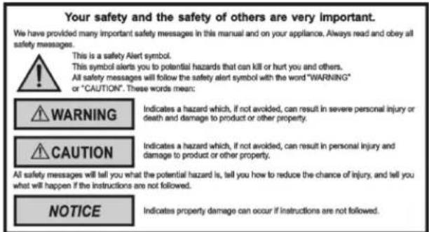
Your safety and the safety of others are very important. We have provided many important safety messages in this manual and on your appliance. Always read and obey all safety messages. This is a safety Alert symbol. This symbol alerts you to potential hazards that can kill or hurt you and others. All safety messages will follow the safety alert symbol with the word "WARNING" or "CAUTION". These words mean: WARNING Indicates a hazard which, if not avoided, can result in severe personal injury or death and damage to product or other property. CAUTION Indicates a hazard which, if not avoided, can result in personal injury and damage to product or other property. All safety messages will tell you what the potential hazard is, tell you how to reduce the chance of injury, and tell you what will happen if the instructions are not followed. NOTICE Indicates property damage can occur if instructions are not followed.IMPORTANT
Do not install and use your portable air conditioner unit before carefully reading this instruction guide.
Please retain this manual brochure for product warranty and future reference
CAUTION
Operate this unit in an ambient of 89^ F or less.
The heating function of the unit should be operated in an indoor ambient temperature between 44°F and 73°F.
Clean air filter periodically to enjoy the most efficient cooling.
When the unit is shut off, please wait at least 3.5 minutes before restarting; this is to prevent the compressor from being damaged.
This unit is for indoor cooling, heating and dehumidifying.
When turning on the unit, the fan will operate but the compressor will start up after the cooling alarm flashes for three minutes.
In heating function, the heating alarm will flash for 3.5 minutes before the compressor and fan start up.
If you have fuses, they should be of the time delay type. Before you install or relocate this unit, be sure that the amperage rating of the circuit breaker or time delay fuse does not exceed the amp rating listed in Table 1.
| Table 1. | |||
| MODEL | CIRCUIT RATING OR TIME DELAY FUSE | REQUIRED WALL RECEPTACLE | |
| AMP VOLT | NEMA NO. | ||
| P08SA, P10SA, P12SA | 15 | 125 5-15P | |
INTRODUCTION
Congratulations on your purchase and welcome to Friedrich!
ZoneAire® Compact: PORTABLE AIR CONDITIONER
The Air Conditioner has been designed and manufactured to the highest standards of modern engineering. Our product not only provides you a remote control to operate all of the functions easily and conveniently but also includes the following benefits:
- 3-IN-1 SYSTEM: Offers cooling, dehumidification and bonus heat for year-round conditioning and comfort.
- Innovative design: One side offers cooling, simply turn the unit around and attach the hose for heating.
- Easy-roll casters.
• Built-in hose storage. - Dual, easy-access antimicrobial nylon filters
• Electronic control pad provides easy identifying icons for simplified user operation - 24-hour programmable timer for cooling, heating and dehumidification modes
- Unique Sleep Control function – Increases temperature 2 degrees every 4 hours
- LCD remote control
UNPACKING INSTRUCTIONS
UNPACKING INSTRUCTIONS
- Place the unit in the correct upright position before unpacking.
- Cut the two packing straps.
- Slide the carton in an upward motion and it will release from the base.
- Grip the carry handles located on either sides of the unit and carefully lift until it slides out of the foam base.
- Remove the hot air outlet to take out the exhaust hose and (upper/lower) hose adapters.
- Install the exhaust hose on the unit before operating the unit.
natural_image
Line drawing of a device with a circular vent and control panel (no text or symbols)CONTENTS
CONTENTS
- Portable air conditioner unit
- Remote control (1 pc)
- A-type window kit
- Upper/Lower hose adapters
- Joint tube
- Exhaust hose (1 pc)
- Batteries (2 pcs)
- User Manual (1 pc)
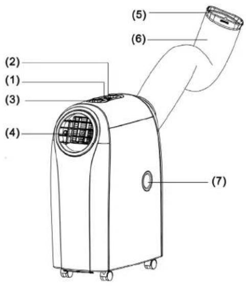
PARTS
- Control panel
- Remote control receiver
- Adjusting Dials
- Adjustable air vent
- Joint tube
- Exhaust hose
- Upside drain hole
- Cool air inlet
- Cool air filter
- Hot air inlet
- Hot air filter
- Downside drain hole
text_image
(2) (1) (3) (4) (5) (6) (7)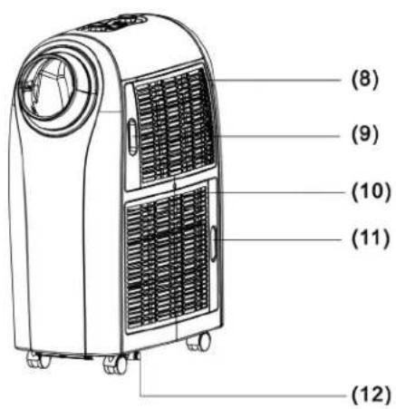
text_image
(8) (9) (10) (11) (12)DISPLAY FUNCTIONS
text_image
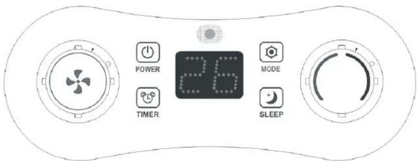
POWER 26 MODE TIMER SLEEP- FUNCTIONS Key Description:
POWER (On/ Off Key)
- Standby mode (Default)
- Turn On/ Off the unit
- Turn on the unit, the indicator lights on.
- Turn of the unit to standby mode, the indicator lights off.
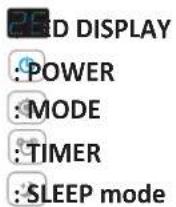
- MODE (Functions switch key) 📋: the switching cycle is Cooling (Default) > Dehumidifying > Heating, and back to Cooling again.
COOLING/Heating/ Dehumidification Modes:
The indicator light turns blue for cooling, red for heating, and green for dehumidification> If the compressor shuts down, the indicator blinks.
The display window shows setting temperature on screen.
- TEMPERATURE REGULATION Knob (UP/Down)
- Rotate the dial ( ) in clockwise direction; the value will increase 1°C/1°F per scale. The maximum value is 30°C/86°F (25°C/77°F). Rotate the dial in a counter-clockwise direction to decrease the value 1°C/1°F per scale. The minimum value is 17°C/63°F(15°C/59°F).
- In DEHUMIDIFYING mode, the dial is inactive.
- PROGRAMMABLE TIMER
- Press the key to activate the timer, the indicator lights on; press the key again to cancel the timer setting, the indicator light will turn off.
- While the unit is operating or in standby, press the key and rotate the dial in clockwise/counter-clockwise direction to set the Auto-Off time from 0 to 24 hours.
- During the TIMER mode, press and hold the key for 1 second, the time increases continuously
- To set the time, press the key 📋 before rotating the dial (). The display will flash the on/ off time during setting and show the time setting on screen.
DISPLAY FUNCTIONS
5. L.E.D. DISPLAY
The display indicates the current setting temperature or the timer setting. When the set temperature or the timer is adjusted, the new setting is shown then the display returns the current set temperature. The display is also used to show error codes should a fault occur, see TROUBLE SHOOTING.
6. FAN SPEED
Rotate the dial ✦ in clockwise direction, the speed changes from F1 (Low) → F2 (Medium) → F3 (High) → AU (Auto)
Rotate the dial + in counter-clockwise direction, the speed changes backwards from AU (Auto) → F3 (High) → F2 (Medium) → F1 (Low)
In COOLING mode, fan speeds are available from F1 (Low), F2 (Medium), and F3 (High) to AU (Auto). Default fan speed is in F2 (Medium) speed. Rotate the knob to F1 (Low) → F2 (Medium) → F3 (High) → AU (Auto) fan speed.
If “AUTO” is selected (During cooling function), “HIGH” or “MEDIUM” or “LOW” will be selected automatically according to the difference between setting temperature and ambient temperature.
7. TIMER MODE
TIMER scale: from 0 to 24 hours.
- Use the TIMER to set the Auto-Off time during operating or in Stand-By mode
- While setting the TIMER, use the ⏻ key or the dial ⭁ is available to adjust to the desired time.
- With each press of the TIMER key, the value on the display will increase from "00"→"01"......→to"24" and back to "00" again.
- Set the Auto-On / Auto-Off timer:
- Press the 📋 key to preset the Auto-Off timer, and the display will flash the setting time. The display will return to show operating mode after 5 seconds.
- Press the ⏻ key before the preset time to cancel the Auto-Off timer, and the unit will be turned off directly.
- While setting the Auto-On timer, you can preset the functions at the same time.
- Press the key to set the Auto-On timer. After setting up, the display shows the rest of time.
- Press the key ☐ before the preset time to cancel the Auto-On timer, and the unit will be turned on directly
- After setting up the Auto-On timer, the unit is still available to be controlled or be switched to other functions.
DISPLAY FUNCTIONS
8. SLEEP CONTROL FUNCTION
In "Sleep" mode, your unit will automatically go into low fan speed allowing the temperature to slowly drift up (in cooling) or down (in heating). See below:
- While in cooling mode, press the SLEEP key to set the temperature. It increases 2^ F after an hour and at most increases 4^ F after 2 hours.
- While in heating mode, press the SLEEP key to set the temperature. It decreases 2^ F after hour and at most decreases 4^ F after 2 hours.
- Press the SLEEP key again to cancel the setting.
9. ALARM
When the water tank is full,"E4" will be displayed on the display panel. To resume operation, please remove the rubber cap of the drain hose to drain out the water firstly. The E4 warning will disappear after draining, and then you can restart the unit by pressing the POWER key.
REMOTE CONTROL FUNCTIONS
| Icon | Function |
 | Cooling |
 | Heating |
 | Dehumidifying |
 | Sleeping |
 | Timer ON/OFF |
 | Temperature |
 | Automatic air flow speed |
 | High speed |
 | Medium speed |
 | Low speed |
text_image
Top view ①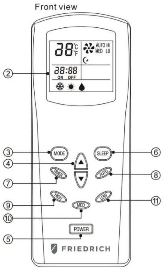
text_image
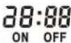
Front view 38°C AUTO HI MED LO 38:88 ON OFF MODE SLEEP TIMER AUTO HIGH LOW MED POWER FRIEDRICHInstruction for the operating keys:
When a remote control signal is transmitted, a transmission icon on the display flashes once, indicating the signal has been transmitted.
REMOTE CONTROL FUNCTIONS
- Transmission window
- Liquidcrystaldisplay
- Mode select key:
Select from among the three functions: cooling, heating and dehumidifying. The fast key function indicates the above operating modes in a cycle when the key is pressed without being released. However, the transmission icon will not appear until the key is released and the confirmed mode is transmitted.
- Setting keys for room temperature:
The set temperature will rise by 1^ F when the ▲ key is pressed once and the set temperature will fall by 1^ F when the ▼ key is pressed once. Both keys have the fast key function and can make the set temperature rise or fall continuously when the keys are pressed without release.
- Power key:
When this key is pressed, the memorized modes and other information about temperature, speed, direction of airflow, sleep, etc., in the remote control will be transmitted to the unit and it will operate correspondingly. When the key is pressed again, the main unit will stop immediately.
- Sleepkey
When this key is pressed, the air flow of the unit changes into sleep mode (low speed).
(1) Press "SLEEP" key, set sleep function; press again, and cancel sleep setting.
(2) The temperature will increase 2^ F half an hour after setting sleep function, and will increase at most 4^ F every two hours after that.
(3) When the main power supply is cut off, the sleep function setting will be cancelled automatically.
(4) When you turn off the unit, sleep function setting will be cancelled automatically.
REMOTE CONTROL FUNCTIONS
7. Timer key:
TIMER-ON: The timer-on is used to turn on the unit automatically after the setting time is over.
- Press the "TIMER" key at stand-by status to set the time desired.
- Once the set time has come to an end. The unit will turn on automatically.
- Press the "POWER" key before time out, the setting time will be canceled and the unit will turn on.
TIMER-OFF: The timer-off is used to turn off the unit automatically after the set time is over.
- Press the "TIMER" key at stand-by status to set the time desired.
-
Once the setting hour has come to an end. The unit will turn off automatically.
-
Press the "POWER" key before the time out, the set time will be canceled and the unit will turn off.
Note: Press "Timer" key when unit is off, The unit will be automatically Turn on, The setting method same as above
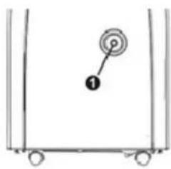
This unit can evaporate the condensation and distribute through the exhaust hose automatically.
- The drain pipe doesn't have to be installed, when the unit is in cool mode. Please make sure that the rubber cap is locked on drain hole, when the unit is running.
- When operating the heating function, the “①” rubber cap on drain hole should be pulled out and proper drain pipe should be installed in order to improve heating.
- When operating the dehumidifying function the “①” rubber cap on drain hose should be pulled out and proper drain hose should be installed.
Please remove the air exhaust hose, connect a drain hose to the drain hole and lead the water to the outside in order to intensify dehumidifying capacity.
When the water tank is full,"E4" will be displayed on the display panel. Please remove the rubber cap "①" of the drain hole to drain out the water first.
After drainage is completed, please restart the unit so it can operate normally.
text_image
Diagram showing a numbered point '1' on a circular target symbol inside a rectangular frame with wheels at both ends.
natural_image
Diagram of a heat exchanger or cooling unit with labeled component (no text or symbols present)MAINTENANCE AND CLEANING
ELECTRICAL SHOCK HAZARD
Disconnect all power before servicing or cleaning. Failure to follow these instructions can result in death, electrical shock or fire.
MAINTENANCE
PLEASE DISCONNECT THE POWER CORD BEFORE CLEANING.
AIR FILTER
The air filter located on the left hand side of the unit and can be removed simply by pulling the frame up.
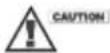
Clean the air filter with a vacuum cleaner ensuring all dust is removed.
CONDENSER/EVAPORATOR
Use a brush attachment with a vacuum cleaner.
text_image
Diagram showing airflow system components of an air conditioner with labeled parts and directional arrows indicating flow direction.Safety Precautions
• Install in an accessible location.
- Only operate the unit in an upright position.
- Do not place in direct sunlight to avoid discoloration of the plastic.
- Do not use the unit on or in water to avoid electrical shock.
- Do not use near gas appliances, flammable liquids, or fires.
Power Sources
- Make sure your electrical receptacle has the same configuration as your air conditioner's plug. If different, consult a Licensed Electrician.
- Do not use plug adapters. Do not use an extension cord. Do not remove ground prong.
- Always plug into a grounded 3 prong outlet. Failure to follow these instructions can result in death, fire, or electrical shock.
Other Warnings
- Do always keep the unit 3 feet away from TV sets or radios to avoid the risk of electromagnetic interference.
- Do always keep the air outlets free from obstructions.
INSTALLATION
PLACE FOR USE
- Because the machine distributes hot air, please don't place or operate in a narrow place.
- Do not work the machine in a humid place.
- Don't place the machine in a sunlit corner otherwise the unit might shut down due to the overheat and the color of the machine may soon fade out.
HELPFUL HINTS
The unit is fitted with a special thermal cut off device.
Please ensure the unit is not placed against objects which will obstruct air intake e.g. furniture or curtains as this will affect its performance dramatically.
Do not overextend the exhaust hose beyond its full extension or attach additional extensions.
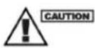
EXHAUST HOSE INSTALL
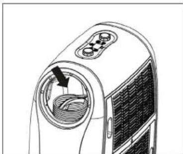
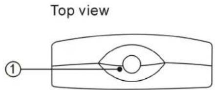
- To attach the flexible exhaust hose to the unit, rotate the hose clockwise (as shown in figure ①) directly onto the hot-air outlet ring.
- To remove the flexible exhaust hose from the unit, rotate the hose counter-clockwise (as shown in figure ②) off of the hot-air outlet ring.

text_image
Diagram illustrating two mechanical or fluid handling setups with labeled components and directional arrows indicating flow or movement.HOT AIR OUTLET INSTALLATION
Follow below steps to assemble hose adapters on the unit before operating.
flowchart
graph LR
    A["Raw Material"] --> B["Coil"]
    B --> C["Coil Ring"]
    C --> D["Final Assembly"]
    D --> E["Final Component with Rotation Arrow"]
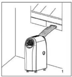
INSTALLATION
WINDOW KIT INSTALL
- Install the Flexible Exhaust Hose and the Adjustable Window Slider Kit vertically or horizontally.
- Slide the window kit to adjust the length of the window.
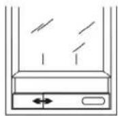
Window elider kit
natural_image
Line drawing of a portable air conditioner unit with ventilation slots and a wall-mounted panel (no text or symbols)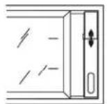
Window slider kit
natural_image
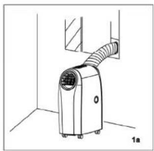
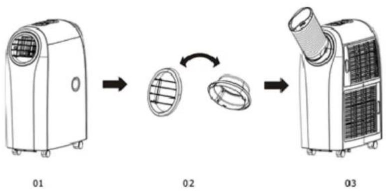
Line drawing of a small outdoor air conditioner unit with a coiled hose and ventilation slots, labeled '1a' (no text or symbols on the device itself)How to enjoy heating function
- Remove and reverse the hot and cold air outlet, and re-install the air outlets as seen in picture 03.
- Turn on the unit around and feed hose through window, or other opening, as shown in "Window Kit Install" section above.
flowchart
graph LR
    A["01 Air Conditioner Unit"] --> B["Internal Structure"]
    B --> C["Rotation Arrow"]
    C --> D["Final Air Conditioner Unit"]
TROUBLESHOOTING
TROUBLESHOOTING
| ERROR CODE | CAUSE TROUBLESHOOTING | |
| E1 | Electrical short on both temperature sensor and PCB | Contact an electrician for repair |
| E2 | Electrical short of temperature sensor copper tube and PCB wiring | Contact an electrician for repair |
| E4 Water plate is full | Pull out the rubber stopper located at the bottom of the unit to drain the water out. | |
(CE) N 842/2006: R410A is a kind of fluorinated greenhouse gases covered by the Kyoto Protocol. Its total global warming potential (GWP) is 2088.
natural_image
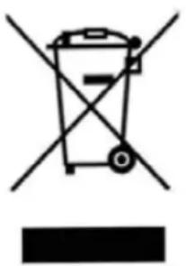
Symbol of a trash bin crossed with a diagonal line and a horizontal bar below (no text or labels)This marking indicates that this product should not be disposed with other household wastes throughout the EU. To prevent possible hazards to the environment or human health from uncontrolled waste disposal, please recycle it to prove the sustainable reuse of material resources. Please ask return and collection systems or contact the retailer where the product was purchased to return your used device, they can recycle products safely.

FRIEDRICH
Friedrich Air Conditioning Co.
10001 Reunion Place, Suite 500
San Antonio, TX 78216
1-800-541-6645
www.friedrich.com
natural_image
White portable air conditioner unit with ventilation grille and brand logo (no visible text or symbols on device body)TABLE DES MATIÈRES
natural_image
Line drawing of a device with a circular vent and internal structure, showing no text or symbols.CONTENU
CONTENU
CONDUIT D'ÉVACUATION
AVIS
natural_image
Simple line drawing of a container with wheels and a numbered mark (no text or symbols)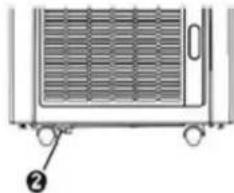
natural_image
Diagram of a refrigerator with ventilation grilles and wheels, no text or symbols presentENTRETIEN ET NETTOYAGE

AVERTISSEMENT
RISQUE DE CHOC ÉLECTRIQUE
text_image
Diagram showing airflow or ventilation system components with labeled parts and directional arrows indicating flow direction.Mesures de sécurité
text_image
Diagram illustrating two mechanical or fluid circulation setups with labeled components and directional arrows indicating flow or movement.INSTALLATION DE L'ORIFICE D'ÉVACUATION D'AIR CHAUD
flowchart
graph LR
    A["Raw T-shaped component"] --> B["Coil with plus sign"]
    B --> C["Coil with ring and end cap"]
    C --> D["Exploded view of mechanical part with arrow indicating rotation or assembly"]
    D --> E["Final assembled device with circular components"]
INSTALLATION
INSTALLATION DE LA TROUSSE D'ÉTANCHÉITÉ DE FENÊTRE
natural_image
Line drawing of a portable air conditioner unit with ventilation slots and a wall-mounted panel (no text or symbols)natural_image
Line drawing of a portable air conditioner unit with airflow path and label '1a' (no text or symbols on device)natural_image
Symbol of a trash bin crossed with no text or labels, accompanied by a black rectangular block below (no readable text or symbols)Friedrich Air Conditioning Co.
10001 Reunion Place, Suite 500
San Antonio, TX 78216
1-800-541-6645
www.friedrich.com