
AVR21 - Receiver ARCAM - Free user manual and instructions
Find the device manual for free AVR21 ARCAM in PDF.
| Product type | Audiovisual receiver (AV receiver) |
| Brand | Arcam |
| Model | AVR21 |
| Output power (2 channels, 8 Ω / 4 Ω) | 110 W / 75 W (70 Hz – 20 kHz, < 0.02% THD) |
| Output power (7 channels, 1 kHz, 0.2% THD) | 90 W / 170 W |
| Number of amplification channels | 7 (configurable: front, center, surround, height, bi-amping, zone 2) |
| HDMI inputs | 7 x HDMI 2.1 (40 Gbit/s, HDCP 2.3) |
| HDMI outputs | 2 (one with eARC, one for zone 2) |
| Analog audio inputs | 6 (including one front AUX) |
| Digital audio inputs | Coaxial and optical |
| Network connectivity | Ethernet, Wi-Fi, Bluetooth |
| Supported audio formats | Dolby Atmos, Dolby TrueHD, DTS:X, DTS-HD, Auro-3D, MQA, PCM up to 192 kHz/24 bit |
| Built-in radio | FM and DAB/DAB+ |
| Automatic calibration | Dirac Live (microphone included) |
| Preamp outputs | 7.1 channels (RCA) |
| Headphone output | 3.5 mm jack, output impedance < 100 Ω |
| Remote control | Universal IR learning remote, RS232, IP, external IR |
| Firmware update | Via USB or network (OTA) |
| Mains power supply | 110-120 V or 220-240 V, 50-60 Hz (manual selection) |
| Power consumption (max) | 1.5 kW |
| Power consumption (standby) | < 0.5 W |
| Dimensions (W x D x H) | 433 x 425 x 171 mm (feet included) |
| Net weight | 16.6 kg |
| Warranty | 5 years (parts and labor, 3 years for disc players) |
| Included accessories | Power cord, remote control (2 AAA batteries), manual, DAB/FM antenna, 3 Wi-Fi/Bluetooth antennas, calibration microphone, USB cable |
Frequently Asked Questions - AVR21 ARCAM
User questions about AVR21 ARCAM
0 question about this device. Answer the ones you know or ask your own.
Ask a new question about this device
Download the instructions for your Receiver in PDF format for free! Find your manual AVR21 - ARCAM and take your electronic device back in hand. On this page are published all the documents necessary for the use of your device. AVR21 by ARCAM.
USER MANUAL AVR21 ARCAM
AV41/AVR31/AVR21/AVR11
HANDBOOK
MANUEL
HANDBUCH
HANDLEIDING
MANUAL
РУКОВОДСТВО
MANUALE
手册
핸드북
EN
HANDBOOK
ARCAM | HDA
AV41/AVR31/AVR21/AVR11
Safety Guidelines
Important Safety Instructions
- Read these instructions.
- Keep these instructions
- Heed all warnings.
- Follow all instructions
- Do not use this apparatus near water.
- Clean only with dry cloth
- Do not block any ventilation openings. Install in accordance with the manufacturer's instructions.
- Do not install near any heatsources such as radiators, heat registers, stoves, or other apparatus (including amplifiers) that produce heat.
- Do not defeat the safety purpose of the polarized or grounding-type plug.
A polarized plug has two blades with one wider than the other. A grounding type plug has two blades and a third grounding prong. The wide blade or the third prong are provided for your safety. If the provided plug does not fit into your outlet, consult an electrician for replacement of the obsolete outlet
- Protect the power cord from being walked on or pinched particularly at plugs, convenience receptacles, and the point where they exit from the apparatus.
- Only use attachments/accessories specified by the manufacturer.
- Use only with the cart, stand, tripod, bracket, ortable specified by the manufacturer, or sold with the apparatus.
When a cart is used, use caution when moving the cart/apparatus combination to avoid injury from tip over.
- Unplugnisapparatus during lightning stormsor when unused for long periods of time.

- Refer all servicing to qualified service personnel.
Servicing is required when the apparatus has been damaged in any way, such as power supply cord or plug is damaged, liquid has been spilled or objects have fallen into the apparatus, the apparatus has been exposed to rain or moisture, does not operate normally, or has been dropped. - Object or liquid entry
WARNING - Take care that objects do not fall and liquids are not spilled into the enclosure through any openings. The equipment shall not be exposed to dripping or splashing. Liquid-filled objects such as vases should not be placed on the equipment. - Climate
The equipment has been designed for use in moderate climates and in domestic situations. - Cleaning
Unplug the unit from the mains supply before clearing.
The case should normally only require a wipe with a soft, lint-free cloth. Do not use chemical solvents for cleaning.
We do not advise the use of furniture clearing sprays or polishes as they can cause permanent white marks. - Power sources
Only connect the equipment to a power supply of the type described in the operating instructions or as marked on the equipment.
The primary method of isolating the equipment from the mains supply is to remove the mains plug. The equipment must be installed in a manner that makes disconnection possible. - Abnormal smell
If an abnormal smell or smoke is detected from the equipment, turn the power off Immediately and unplug the equipment from the wall out at. Contact your dealer and do not reconnect the equipment. - Damage requiring service
The equipment should be serviced by qualified service personnel when:
A. The power-supply core or the plug has been damaged, or
6. Objects have fallen, or liquid has spilled into the equipment, or
C. The equipment has been exposed to rain, or
12. The equipment does not appear to operate normally or exhibits a marked change in performance, or
E. The equipment has been dropped or the enclosure damaged.

CAUTION: To reduce the risk of electric shock, do not remove cover (or back). No user serviceable parts inside. Refer servicing to qualified service personnel.
WARNING: To reduce the risk of fire or electric shock, do not expose this apparatus to rain or moisture.
The lightning flash with an arrowhead symbol within an equilateral triangle, is intended to alert the user to the presence of uninsulated 'dangerous voltage' within the product's enclosure that may be of sufficient magnitude to constitute a risk of electric shock to persons.
The examination point within an electrical triangle is intended to alert the user to the presence of important operating and maintenance (servicing) instructions in the literature accompanying the product.
CAUTION: In Canada and the USA, to prevent electric shock, match the wide blade of the plug to the wide slot in the socket and insert the plug fully into the socket.
Class II product
This equipment is a Class II or double insulated electrical appliance. It has been designed in such a way that it does not require a safety connection to electrical earth ("ground" in the U.S.)
Warning
Mains plug/appliance coupler is used to disconnect device and i. shall remain readily operable.
Safety Compliance
This equipment has been designed to meet the IEC/EN 60065 international electrical safety standard.
This device complies with Part 15 of the FCC Rules. Operation is subject to the following two conditions:
- This device may not cause harmful interference, and
- This device must accept any interference received, including interference that may cause undesired operation.
The building installation shall be regarded as providing protection in accordance with the rating of the wall socket outlet.
Caution on installation
For proper heat dispersal, do not install this unit in a confined space, such as a bookcase or similar enclosure.
☐ More than 0.3m (12in) is recommended.
☐ Do not place any other equipment on this unit.


FCC Information (for US customers)
PRODUCT
CONTAINS TRANSMITTER MODULE FCC ID:
APILUXASTR01, APILUXABT01
This product complies with Part 15 of the PCC Rules. Operation is subject to the following two conditions: (1) this product may not cause harmful interference, and (2) this product must accept any interference received, including interference that may cause undesired operation.
IMPORTANT NOTICE: DO NOT MODIFY THIS PRODUCT
This product, when installed as indicated in the instructions contained in this manual, meets FCC requirements. Modification not expressly approved by ARCAM may void your authority, granted by the FCC to use the product.
CAUTION (-or Bluetooth/Wi-H)
- To comply with FCC RF exposure compliance requirement, separation distance of at least 20 cm must be maintained between this product and all persons.
- This product and its antenna must not be co-located or operating in conjunction with any other antenna or transmitter.
NOTE
This product has been tested and found to comply with the limits for a Class B digital device, pursuant to Part. 15 of the FCC rules. These limits are designed to provide reasonable protection against harmful interference in a residential installation.
This product generates, uses and can radiate radio frequency energy and, if no. installed and used in accordance with the instructions, may cause harmful interference to radio communications. However, there is no guarantee that interference will not occur in a particular installation. If this product does cause harmful interference to radi or television reception which can be determined by turning the product OFF and ON, the user is encouraged to try to correct the interference by one or more of the following measures:
☐ Reorient or relocate the receiving antenna.
L. Increase the separation between the equipment at the receiver.
- Connect the product into an outlet on a circle different form that to which the receiver is connected
L Consult the local retailer autorised to distribute this type of product or an experienced radio / TV technician for help.
IC Information (For Canadian customers)
PRODUCT
CONTAINS TRANSMITTER MODULE IC:
6132A-LUXASTR01, 6132A-LUXABT01
This product complies with RSS-247 of Industry Canada. Operation is subject to the following two conditions: (1) this product may not cause harmful interference, and (2) this product must accept any interference received, including interference that may cause undesired operation. This Class B digital apparatus complies with Canadian ICES 003.
CAUTION
To reduce potential radio interference to other users, the antenna type and its gain should be so chosen that the equivalent isotropically radiated power (e.l.p.) is not more than that permitted for successful communication. () the device for operation in the band 5,150–5,250 MHz is only for indoor use to reduce the potential for harmful interference to co-channel mobile satellite systems. () high-power radars are allocated as primary users (i.e., priority users) of the bands 5,250–5,350 MHz and 5,650–5,850 MHz and that these radars could cause interference and/or damage to LE-LAN devices.
6132A-LUXASTR01, 6132A-LUXABT01
RF Exposure Information
This equipment complies with FCC/TC radiation exposure limits set forth for an uncontrolled environment and meets the FCC radio frequency (RF) Exposure Guidelines in Supplement C to QH165 and HS-137 of the IC radio frequency (RF). Exposure rules. This equipment has very low levels of RF energy that are deemed to comply without testing of specific absorption ratio (SAR).
Safety Information (for European customers)
Avoic high temperatures. Allow for sufficient heat dispersion when installed in a rack.
Handle the power cord carefully. Hold the plug when unplugging the cord.
Keep the unit free from moisture, water, and dust.
Unp.ug the power cord when not using the unit for long periods of time.
Do not obstruct the ventilation holes.
Do not let foreign objects into the unit.
Do not let insecticides, benzene, and thinner come in contact with the unit.
Never disassemble or modify the unit in any way.
Ventilation should not be impeded
Ventilation openings with items, such as newspapers, tablecloths or curtains.
Naked flame sources such as lighted candles should not be placed on the unit.
Safety Information (for European customers)
Observe and follow local regulations regarding battery disposal.
Do not expose the unit to dropping or splashing fluids.
Do not place objects filled with liquids, such as vases, on the unit.
Do not handle the mains cord with wet hands. When the switch is in the OTT position, the equipment is not completely switched off from MAINS.
The equipment shall be installed near the power supply so that the power supply is easily accessible.
A note about recycling
This product's packaging materials are recyclable and can be reused. Please dispose of any materials in accordance with the local recycling regulations. When discarding the unit, comply with local rules or regulations.
Batteries should never be thrown away or incinerated but disposed of in accordance with the local regulations concerning battery disposal.
This product and the supplied accessories, excluding the batteries, constitute the applicable product according to the WCEE directive
Correct disposal of this product
These markings indicate that this product should not be disposed with other household waste throughout the EU.

text_image
PbTo prevent possible harm to the environment or human health from uncontrolled waste disposal and to material resources, this product must be disposed of responsibly.
In disperse of your product, please use your local return and collection systems or console, the installer where the product was purchased.
Radio specifiction (for Europe model):
| Type Frequency Range Max, RF Power | ||
| Bluetooth 2,402-2,800MHz, 70dBm | ||
| WLAN(2.4GHz,1.740-2,683.5MHz,70dBm) | ||
| 5GHz Radio 5,150-5 | 5,250-5,350MHz, 23dBm | |
| 5,470,5,850MHz, 30dBm | ||
| Note: The above specifications are based on the RE directive. There is a possibility it can vary by country. | ||
Welcome
Thank you and congratulations...
...for purchasing your Arcam HDA Receiver.
Arcam has been producing specialist audio products of remarkable quality for over three decades and the new Receivers are the latest in a long line of award-winning Hi-Fi. The design of the HOA range draws upon all of Arcam's experience as one of the UK's most resected audio companies, to produce Arcam's best performing range of products yet - designed and built to give you years of viewing and listening enjoyment.
This handbook is intended to give you a detailed guide to using the Receiver. It starts by giving advice on installation, moves on to describe how to use the product and finishes with additional information on the more advanced features. Use the contents list shown on this page to guide you to the section of interest.
We hope that your HDA receiver will give you years of trouble-free operation. In the unlikely event of any fault, or if you simply require further information about Arcam products, our network of dealers will be happy to help you. Further information can also be found on the Arcam website at www.arcam.co.uk.
The HDA development team
Contents
Safety Guidelines EN-2
Welcome
Before You Begin... EN-6
Trademark Acknowledgments EN-8
Rear Panel Connections and Controls EN-9
Audio/Video Connections EN-10
Connection Guide EN-12
Radio & Wireless Audio Connectors EN-13
Other Connectors EN-14
Speakers
Connecting Speakers EN-16
Operation
Extended front panel menu EN-18
Updating firmware via USB EN-18
Front Panel Operation EN-19
Remote Control EN-20
Customising the Remote
Essential Setup
Auto Speaker Setup
Setup Menus
Connecting to a Network
EN-4
EN-15
EN-17
EN-22
EN-28
EN-29
EN-30
EN-34
Decoding Modes EN-35
Tuner Operation EN-37
Troubleshooting EN-38
Specifications EN-40
Worldwide Guarantee EN-42
Professional Installation?
It may be that the Receiver has been installed and set up as part of your Hi Fi installation by a qualified Arcam dealer. In this case, you may wish to skip the sections of this hardbook dealing with installation and setting up, and move directly to the sections dealing with using the unit. Use the Cantenis list to guide you to these sections.
DIY setup?
The Receiver is a powerful and sophisticated piece of AV equipment. If you are setting the unit up yourself, it is recommended that you read this handbook thoroughly before beginning. For instance, correct speaker configuration and placement is a key to getting the most out of your Receiver and making sure that all the elements of your system work in harmony.
Before You Begin...

text_image
ARCAM HOMETHATRE PHONES AUX AVR31 MENU IN+/- IN+/- OK INFO/ < MODE/ > MUTE DIRECT DISPLAY ZONE POWERArcam HDA Receiver
The Receivers are high-quality and high-performance home-cinema processors and amplifiers built to Arcam's quality design and manufacturing standards. They combine digital processing with high-performance audio and video components to bring you an unrivalled home entertainment centre.
The Receiver allows switching and control of seven analogue and six digital audio sources in addition to internal EM and DAB+ radios – as well as networked audio sources – making any of the models an ideal hub for both home-cinema and two-channel stereo systems.
Since many of these source components are also capable of generating video signals, the Receiver includes broadcast quality switching for HDMI (xHDMI2.1 @4CGbit/s,HDCP2.3) video/audio signal's Control of the Receiver is either by front panel control buttons, R remote control, IP (Ethernet) control or RS232 port.
The remote control supplied with the Receiver is a multi-device 'universal' learning remote control which is simple to use, and once set up is able to control a complete system. It can be programmed using its vast internal code library to control CD and BD players, PVRs, TVs and other devices.
The installation of the Receiver in a listening room is an important process which requires care at every stage. For this reason, the installation information is very comprehensive and should be followed carefully to achieve an unrivalled level of performance.
The Receiver is designed to produce a level of performance that will truly bring music and movies to life.
Placing the unit
Place the unit on a level, firm surface, avoiding dire sunlight and sources of heat or damp.
☐ Do not place the Receiver on top of a power amplifier or other source of heat.
Do not place the amplifier in an enclosed spa such as a bookcase or closed cabinet unless there is good provision for ventilation (see page EN-2). The Receiver will run warm during normal operation.
☐ Do not place any other component or item on the air of the amplifier as this may construct airflow around the heat-sink, causing the amplifier to run hot. (The unit, placed on top of the amplifier would become hot, too.)
- Make sure the remote-control receiver on the front panel display is unobstructed, otherwise this will impair the use of the remote control. If line of sight is impractical, a remote control repeater can be used with the rear panel connector (see page EN-34).
Do not place your record deck on top of the unit. Record decks are very sensitive to the noise generated by mains power supplies which will be heard as a background 'hum' if the record deck is too close.
Power
He amplifier is supplied with a moulded mains plug already fitted to the lead. Check that the plug supplied fits your supply - should you require a new mains lead, please contact your Arcam dealer.
If your mains supply voltage or mains plug is different, please contact your Arcam dealer immediately.
The Receiver can be switched for operation between 220-240V (switch position 230V) and 110-120V (switch position 115V).
NOTE: Ensure that the Receiver is switched off and the power lead removed before changing the position of the voltage range switch.
Push the PC plug end of the power cable into the socket on the back of the amplifier, making sure that it is pushed firmly. Plug the other end of the cable into your mains socket and, if necessary, switch the socket on.
The Receiver can be turned on using the power switch on the front panel. While switched on, the front panel (HD) will is slow white.
Standby power
The Receiver can be switched into standby mode using the button on the remote control. While in standby mode the front panel LED will glow red and (with default settings) power consumption is less than 0.5 Watts.
While in Stancy mode, it may be possible to hear a slight residual hum coming from the mains transformer inside the amplifier. This is perfectly normal. However, if the unit is to be left unused for an extended period, we recommend that you disconnect it from the mains supply to save power.
Interconnect cables
We recommend the use of high-quality screened cables that are designed for the particular application. Other cables will have different impedance characteristics that will degrade the performance of your system (for example, do not use ceiling intended for video use to carry audio signals). All cables should be kept as short as is practically possible.
It is good practice when connecting your equipment to make sure that the mains power-supply cabling is kept as far away as possible from your audio cables. Failure to do so may result in unwanted noise in the audio signals.
For information on speaker cabling, please refer to the 'Speakers' section, beginning on page EN 16.
Radio interference
The Receiver is an audio device containing microprocessors and other digital electronics. Each model has been designed to very high standards of electromagnetic compatibility.
This is a Class A product. In a domestic environment, this product may cause radio interference, in which case the user may be required to take adequate measures.
If the Receiver causes interference to radio or television reception (which can be determined by switching the Receiver off and on), the following measures should be taken:
☐ Re-orient the receiving antenna or route the antenna cable of the affected device as far as possible from the ARCAM Receiver and its cabling.
□ Relocate the affected device with respect to the ARCAM Receiver.
11 Connect the affected device and the Receiver to different mains outlets.
if the problem persists, please contact your Arcam dealer.
Trademark Acknowledgments
| Dolby Atmos | Dolby Vision, Dolby Atmos, Dolby Audio |
| Dolby Audio | Manufactured under license from Dolby Labscarside, Dolby, Dolby Vision, Dolby Audio, Dolby Audio, and the double-D symbol are registered trademarks of Dolby Labscarside. |
| Dolby Vision | |
| dtsX® | DTS:X®For DTS patents see http://patentsdts.com Manufactured under license from DTS Licensing Limited. DTS, the Symbol, DTS in combining bin with the symbol. DTSX and the DTSX logo are registered trademarks or trademarks of DTS, inc in the United States and/or other countries. » DTS, Inc. All Rights Reserved. |
| dtsVITAL | DTS Virtual:XTMFor DTS patents see http://patentsdts.com Manufactured under license from DTS Licensing Limited. DTS, the Symbol, DTS and the symbol together. VirtualX and the DTS VirtualX logo are registered trademarks and/or trademarks of DTS, Inc. in the United States and/or other countries. » DTS, Inc. All Rights Reserved. |
| IMAXENHANCED | IMAX® & DTS®Manufactured under license from IMAX Corporation. MAX® is a registered trademark of IMAX Corporation in the United States and/or other countries. For DTS patents see http://patentsdts.com Manufactured under license from DTS Licensing Limited. DTS, the Symbol, DTS and the symbol together are registered trademarks or trademarks of DTS, inc in the United States and/or other countries. » DTS, Inc. All Rights Reserved. |
| ● PLUGO® | Auro-30TMManufactured under license from Auto Technologies. Auto, Auto 3D, Auto Codoc and Auto-Mark are registered trademarks of Auto Technologies. |
| AAC/AAC PlusandPlus, as a trademark of Coding Technologies See http://codtech.whost.maris.net for note information. | |
| HOMI | HOMI, the HDMI logo and HighOflin Iran Multimedia Interactive are registered or registered trademarks of HDMI Licensing LLC. |
| Bluetooth® | The Bluetooth® word mark and logos are registered trademarks owned by the Bluetooth 5G, Inc. and any use of such marks by iTalkAN International Industries, Incorporated is under some. Other trademarks and trade names are those of their respective owners. |
| Qualcomm®opUCHD | Qualcomm is a trademark of Qualcomm incorporated, registered in the United States and other countries, apX is trademarks of Qualcomm Technologies international, Ltd., registered in the United States and other countries. |
| Apple Apple AirPlay | Apple, AirPlay and the AirPlay logo, iPod, iPhone and iPad are trademarks of Apple Inc, reg stored in the U.S. and other countries. App Store is a service mark of Apple Inc.AirPlay 2 works with iPhone, iPad, and iPod touch with OS 11.4 or later, Mac with OS X Mountain Lion or later, and PC with Lunes 10.2.2 or later. |
| WiFi CERTIFIED | The Wi-Fi CLR/IIHLD Logo certification marks of the WiFi Alliance. |
| D:\Youwatchbase | Google, Google Play, Chancrant, and other related marks are trademarks of Google LLC. The Google Assistant requires an internet connection and is not available in certain countries and languages. Availability and reach of certain features and services are device, server, and network deployment and may not be available in all areas. Controlling certain devices in your home requires compatible smart devices. Subscribers for services and applications may be required and additional terms concite on and/or charges may apply. |
| vTuner | This product is protected by certain intellectual property rights of NAMS and bridgeCo. Use or distribution of such technology outside of this product is prohibited without a license from NAMS and bridgeCo or an authorized residency. |
| MP3 | VPGCI layer-3 audiodecoding Technology licensed from Haushofel's and Thomson multimedia. |
| Spotify® | Licenses:The Spotify software is subject to third party licenses found here;https://developer.spotify.com/legal/third-party licenses/ |
| FLAC | FLAC Decoder Copyright © 2000, 2001, 2002, 2003, 2004, 2005, 2006, 2007, 2008 Josh Caillon |
| Redistribution and use in source and binary forms, with or without modification, are permitted provided that the following conditions are met. | |
| Redistributions of source code must retain the above copyright notice, this list of conditions and the following disclaimer. | |
| Redistributions in binary form must reproduce the above copyright notice, this list of conditions and the following disclaimer in the documentation and/or other materials provided with the distribution. | |
| Neither the name of the Xipong Foundation not the names of its contributions may be used to encode or promote products derived from this software without specific prior within permission. | |
| THIS SOU WAR IS PROVIDED BY THE COPYRIGHT HOLD IS AND CONTRIBUTIONS AS IS AND ANY EXPRESS OR IMOULD WARRANTY INCLUDING BUT NOT INVOLID TO THE IMPULD WARRANTY OF MERCHANTABILITY AND FITNESS FOR A PARTICULAR PURPOSE ARE DISCLAIMED IN NO EVENT SHALL THE FOUNDATION OR CONTRIBUTORS BE LIABLE FOR ANY DIRECT INDIRECT, INCIDENTAL, SPECIAL, EXTERMACY, OR CONSEQUENTIAL DAMAGES INCLUDING BUT NOT LIMITED TO PROCUREMENT OF SUBSTITUTE GOODS OR SERVICES LOSS OF USE DATA OR PROFITS OR BUSINESS INTERRUPTIONS HOWEVER CAUSED AND ON ANY THEORY OF LIABILITY WHETHER IN CONTRACT STRICT LIABILITY OR TORT INCLUDING NEGLIGENCE OR OTHERWISE ARISING IN ANY WAY OUT OF THE USE OF THIS SOU WAR ONLY ADMISED OF THE POSSIBILITY OR SUCH DAMAGE. |
| MQA (Master Quality Authenticated)MQA is an award-winning stitch technology that delivers the sound of the original master recording. The master VQA file is fully authenticated and is small enough to stream or download.Vitik monoculs for more information.Aware MPA, Include MQA technology, which enables you to play back MQA audio files and streams, delivering the sound of the original master recording."MQA on MQA Study indicates that the source is decorating and playing an VQA stream or live, and denotes proerance to ensure that the sound is critical to that of the source material. MQA studio indicates it is playing an MQA Studio file, which has other been approved in the studio by the artist producer or has been verified by the copyright owner.MQA and the Sound Wave Device are registered trace marks of MQA Limited in 2016 |
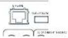
Rear Panel Connections and Controls
EN

text_image
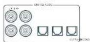
AVR31 AVR21 AVR11 NETWORK CONNECTORS For information, see page EN-13, EN-14. HDMI CONNECTORS For information, see page EN-10. USB SOCKET See page EN-14. PREAMLIFIER INPUTS See page EN-11. FM/DAB FM/ serial socket, or DAB serial socket. DIGITAL CONNECTORS Coaxial and optical digital audio connectors, see page EN-11. NETWORK/BLUETOOTH CONNECTORS For information, see page EN-13. PREAMLIFIER OUTPUTS See page EN-11. SPEAKER OUTPUTS FOR INFORMATION, see page EN-16. POWER INLET Connect the correct mains cable here VOLTAGE SELECT Ensure the voltage selected matches your local power supply. SERIAL AND IR CONTROL Serial control, trigger and IR connectors, see page EN-14. ARCAM CONNECTIONS FOR IT AVR31 FL SL FR SR EN-9
Please read the 'Placing the unit', 'Power' and 'Interconnect cables' sections on page EN-7 before connecting up your Receiver!


Audio/Video Connections
Before connecting your Receiver to your source components and speakers, please read through the next five pages which will explain all the input and output, connectivity that is available. The 'Speakers' section explains how to connect up your speakers to avoid damage to the amplifier and how to arrange your speakers for best performance.
General
The inputs are named to make it easier to reference connected devices (e.g. Bbr) or by all have the same input circuit, so there is no reason why you should not connect a different device to any of the inputs. For example, if you had two BD players and the AV input was not being used, then the second BD player could be connected to the AV input.
When connecting a video source, its audio must be connected to the corresponding sockets. For example, if you had a satellite decoder plugged into a SARideo input, the audio must be connected to the SARDio inputs!
Making Connections
- Take care to place cables as far from any power supply cooling as is practicable, to reduce hum and other noise problems.
NOTE: For each input, you must set the 'Video Source' and 'Audio Source' settings according to the connection type. (see "Input Config." on page EN-31)

HDMI Connectors
PVR, UHD, BD, SAT, AV, GAME, STB
Connect the HDMI video outputs of your source equipment to these corresponding HDMI inputs.
OUTPUT (Zone2 - AVR21, AVR31, AV41)
Connect this output to the HDMI video input of your display device. Output1 is compatible with HDMI Enhanced Audio Return Channel (eARC). If you have a supported television then sound from the television's internal tuner (e.g. Freeview, Freesat, DVB T) will be available using the Receiver's Display input.
Digital audio connectors
SAT, PVR, BD, CD, STB, AV
Connect these inputs to the digital outputs of your available source equipment.
Zone 2 connectors (AVR21, AVR31, AV41)

The Z2 out HDMI connector can be used to connect the output of the Receiver to a system located in a second room.
Analogue preamplifier outputs


All preamplifier analogue outputs are buffered, have a low output impedance, are at the level and follow the Zone 1 volume control setting. They are able to drive long cables or several inputs in parallel if required.
For more information on connecting speakers or additional power amplifiers, see pages EN-9 and EN-16.
he AVI has X-R outputs in addition to the phano pre-outs for connection to an external amplifier.
Analogue audio inputs
STB, GAME, AV, BD, PVR, CD
Connect the left and right inputs to the left and right outputs of your source equipment.
Front panel AUX input

The front panel AUX input can be used as an analogue input, using a stereo 3.5mm lead.
Front panel PHONES socket
This socket accepts headphones with an impedance rating between 32Ω and 500Ω fitted with a 3.5mm stereo jack plug. The headphone socket is always active, except when Receiver is muted.
When the headphone jack is inserted, the speaker outputs and analogue preampifier outputs are automatically muted.
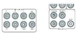
Connection Guide
Blu-ray Disc (BD)/DVD player
The diagram shows how to make audio and video connections from a typical BD/DVD player.
Whether HDV, digital or analogue connections are used, connecting using the input/inputs labeled BD on the Receiver will aid a operation.
Satellite receiver
A satellite receiver is connected with the same order of preference according to the output, provided by the satellite receiver.
CD player
Connect the digital output to the digital CD input of the Receiver and analogue output to the analogue CD input of the Receiver, using a high quality interconnect cable.
NOTE: For each input, you must set the 'Audio Source' setting according to the connection type. (see "Input Config." on page EN-31)

text_image
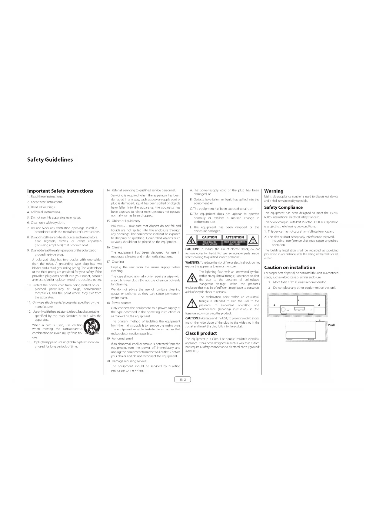
CD BD/SAT ARCAM OUTPUT AVIOLATE AUDIO OUT DIGITAL AUDIO OUT COMPONENT VIDEO OUT HDMI OUT AVIOLATE AUDIO OUT DIGITAL AUDIO OUT P1 P2 P3 C NEXT LEFT NEXT LEFT NEXTRadio & Wireless Audio Connectors
EN
DAB/FM Connector
The Receiver is fitted with an FM and a DAB/DAB1 receiver module. The type of aerial you need depends on your listening preferences and the local conditions
Your Receiver is capable of superb radio reception, but only it is receiving a good quality transmission sign.
Try the aerials supplied with your unit. If you are in a medium to strong signal area, these should be adequate for good exception. In areas with poor signal strength, you may require a roof or loft mounted aerial.
Contact you local Arcam dealer or aerial installation experts for advice about local reception conditions.
In strong signal areas, the DAB/FM-T wire aerial supplied can be used with reasonable results. Mount the aerial as high up as possible on a wall.
In the UK the T-elements need to be positioned vertically for DAB reception since broadcasts are vertically polarised. In other localities, check with your Arcam dealer or try both horizontals and vertical positions for best reception.
Try each usable wall of the room to see which gives best reception and use tacks or adhesive tape to secure the aerial in a I shape, but note that, no tacks should come into contact with the internal wire of the aerial.
When installed and receiving DAB/FM, check the signal strength by pressing the front panel or remote controls INFO button until the signal quality indicator is displayed.
In weak signal areas, a high gain, externally mounted or roof mounted aerial is desirable in order to receive the highest number of services.
In Band 11 transmission areas (such as the UK), use a multi-element Yagi aerial with the elements mounted vertically, as the transmissions are vertically polarized. If you are close to more than one transmitter, use an omnidirectional or foled dipole aerial
If the DAB services in your area are transmitted on I-band, then ask your dealer for advice for the best aerial to use.
Wi-Fi/Bluetooth
f using the Wi-Fi or Bluetooth features of the Receiver, please attach the single antenna for the Bluetooth and the two antennas for the Wi-Fi.
Other Connectors
Serial connector
RS232 serial connector

The connector is used with control devices having an RS232 serial port (for example, Crestron and AMX touch-screen controllers).
Network connector
Networking is a large subject and only the briefest guidelines are presented in this handbook. Please contact your Arcam dealer or specialist installer for more information about, introducing the Receiver into your computer network.
Ethernet
If an Ethernet cable is connected, the Receiver will automatically attempt to connect to your network.
You should use CATS cable plugged into the RJ45 socket labelled ETHERNET on the rear panel.
If your network uses static IP addressing rather than DHCP, you will need to provide IP address, gateway and DNS; see page EN-34 for information on setting up the network.
USB connector
The Receiver can be updated via the USB socket or the rear of the unit, if no network connection and so "Over The Air" update is not available.
Trigger connectors


The trigger connectors (TRIG Z1 and TRIG Z2) provide an electrical signal whenever the Receiver is switched on and the relevant zone enabled.
The trigger signal can be used to switch on and off compatible pieces of home entertainment equipment, for example, you could set up a trigger to turn on your television and BD player whenever the Receiver was switched on.
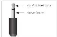
There are two trigger output sockets on the Receiver, each capable of outputting a 17V, 70mA switching signal. The socket is designed for more 3.5mm jacks tip is the trigger output, sleeve is ground.
TRIG Z1
Use for remotely turning on and all power amps or source equipment for Zone 1. On = 12V, Off = 0V
TRIG Z2 (AVR21, AVR31, AV41)
Use for remotely turning on and off power amps or source equipment for Zone 7. On = 12V, Off = 3V.
Infrared (IR) connectors

The infrared inputs (Z1 IR and Z2 IR) allow the connection of external IR receivers, either when the Receiver front panel IR receiver is fully or partially obstructed or to allow the use of a remote control in /one 7.
There are two IR inputs on the Receiver, each designed for stereo or mono 3.5mm jacks. Tip is the modulated signal, sleeve is ground.
Z1 IR
this input is intended for use with a local IR receiver when the front panel of the Receiver is blocked.
Z2 IR (AVR21, AVR31, AV41)
This input is intended for use with an IIF receiver in Zone 2 to allow remote control of Receiver from a second room.
A supplier of infra-red receivers and emitter accessories and systems is Xantech. See www.xantech.com for more information, or ask your Arcam dealer.
NOTE: The IR inputs on the Receiver are designed for modulated signals. If the external IR receiver demodulates the IR signal, it will not work. Also the unit does not provide power for external receivers on the IR jack, therefore an external power source will be required.
NOTE: Sockets referring to 'Z2' relate to connections used in multi-room installation. For more information on these connectors, see page EN-11.
Speakers
The AVRS/AVR11/AVR21/AVR31/AV41 allows you to connect up to sixteen speakers. The AVR1 is designed to be used with additional power amplifiers for all channels. The AVRS/AVR11/AVR21/AVR31 has 7 channels of amplification. 5 channels of amplification correspond to speakers installed in the front left, centre, front right, surround left, surround right. The remaining 2 channels of amplification can be assigned as:
□ bi-amp the front left and right
□ surround back left and surround back right
□ height 1 left and right
□ Zone 2 left and right (AVR21, AVR31, AV41)
Height, front left, height, front right, height back left, height back right and five more additional speakers can be attached using an additional power amplifier, see page EN-16 for more information.
With the addition of correctly installed and configured height channels. Do by Atmos for the home, DTS:X or Auro 3D brings the ultimate cinema sound experience to your home theatre to create powerful, moving audio that flows around you.
The configuration and placement of your speakers is very important. All speakers, with the exception of the subwoofer(s), should be arranged around your normal viewing/listening position. The subwoofer should be placed in a position which gives an even frequency response in all listening positions. Incorrect placement leads to bass boom in some areas. Often the only way to find a good position for your subwoofer(s) is by experimentation. A good place to start experimenting is close to a wall but at least 1m away from any corners. You can also consult your subwoofer handbook for placement suggestions.
Connecting Speakers
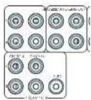
To connect each of the speakers, uncrew the corresponding terminals on the back of the Receiver, Inscri, the speaker wires through the hole in each post and screw the terminals back up. Make sure that the red (positive/+) terminal of the speaker is connected to the red (positive/+) terminal on the back panel, and the black (negative/-) terminal of the speaker is connected to the black (negative/−) terminal on the back panel.

text_image
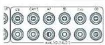
SFLASIL CULIFUS + SR FR C FL SL - SR FR C FL SL CLASS WARSIt is important that, no stray strands of wire from these connections are allowed to touch another cable or the product casing. Failure to ensure this can cause a short circuit and damage your Receiver.
Ensure the unit is switched off whilst connecting speakers. Do not over-tighten the loudspeaker terminals, or use a wrench, pliers, etc., as this could damage the terminals and this would not be covered under the product's warranty.
Speaker cables
The speakers should be connected to the amplifier using good-quality, high-purity, low impedance copper cables. Cheap speaker cables should be avoided – they are a false economy and can significantly degrade the sound quality.
The cable runs to the speakers should be as short as practicable. Connections to the speaker terminals should always be finger light, whether using bare wires or spade connectors.
Bi-amping the Front Left & Front Right speakers
BI ramping is the use of two amplifier channels per speaker. BI ramping can provide better sound quality than conventional single wiring. If you do not have Surround Back speakers (i.e., you have a 5 in surround system, not a 7 in system) then you can use the spare Surround Back speaker outputs to bi-ampify the front left and right speakers, if your speakers support BI- ramping. The spare channels can alternatively be used to power stereo speakers in another room (Zone 2).
Speakers that support blamping have two sets of 17 terminals per speaker, usually linked together by metal strips. These metal strips MUST be removed when blamping; failure to remove them will result in damage to the amplifier that is not covered under warranty.
To ob-amp the front left and right speakers, remove the metal strips from the speaker terminals. Connect the woofer or LF terminals to the FL and FR terminals on the Receiver. Connect the tweeter or HF terminals to the SBL and SBR terminals on the Receiver. Finally, navigate to the Setup Menu 'Spkr Types' and set the 'Use Channels 647 for' menu option to 'BIamp L-RR' see page EN-32.

flowchart
graph TD
    A["HF"] --> B["LF"]
    B --> C["SBR"]
    C --> D["FR"]
    D --> E["FL"]
    E --> F["SBL"]
    F --> G["HF"]
    G --> H["LF"]
    H --> I["Warning Symbol"]
    style A fill:#f9f,stroke:#333
    style B fill:#f9f,stroke:#333
    style C fill:#ccf,stroke:#333
    style D fill:#ccf,stroke:#333
    style E fill:#ccf,stroke:#333
    style F fill:#ccf,stroke:#333
    style G fill:#f9f,stroke:#333
    style H fill:#f9f,stroke:#333
    style I fill:#f9f,stroke:#333
Connecting Subwoofers
The Receiver also allows up to four active subwoofers to be connected to the SUB or Ch13/14/15/16 outputs. Refer to your subwoofer handbook for the correct setting up and connection procedure for your particular subwoofers).
Using external power amplifiers
The internal power amplifier of the Receiver can be supplemented or replaced with external power amplification, such as the Arcam PA720. Connect the PREAMP OUT sockets to your power amplifier inputs

FL, FR
Connect these to the equivalent Right and Left front channels of your power amplifier.
C
Connect these to the Centre front channel of your power amplifier.
SUB
Subwoofer outputs. Connect this to the input of your active subwoofer(s), if present.
SR, SL
Surround Right and Surround Left outputs. Connect these to the Surround Right and Left power amplifier inputs.
SBR, SBL
Surround Back Right and Surround Back Left outputs. Connect these to the Surround Back Right and Surround Back Left power amplifier inputs.
Height 1 (Height Front), Height 2 (Height Back)
Height Front and Height Back Connect these to the Height channel power amplifier inputs.
All preamplifier analogue outputs are buffered, have a low output impedance and are at line level. They are able to drive long cables or several inputs in parallel if required.
Operating your Receiver
For information display we recommend you use the OSD (On-Screen Display) on your display device wherever possible.
Switching on
Press the front panel power button in. The power LED will glow white. When initialisation is complete, the display shows the volume setting and the name of the selected input.
Please wait until the unit has finished initialising before operating the Receiver. It is recommended that if the unit is switched off, you should wait at least 10 seconds before switching the unit back on.
Standby
The Receiver has a standby mode which can be entered by pressing STANDBY on the remote control. When in standby mode, the display is blank and the POWER Iowa rod.
If the unit is to be left unused for an extended period, we recommend that you disconnect it from the mains supply to save power.
To switch on from standby
Press the STANDBY button on the remote control, any key on the front panel (other than the power button) or rotate the volume knob.
Front panel display
The Receiver is ready for use after about four seconds.
The display window shows the currently selected source and the last selected information view setting (this information line can be changed using the InFction).
The current volume setting for Zone 1 is displayed on the front panel. The volume setting for Zone 2 is displayed temporarily whenever it is adjusted.
The front panel display is also used for unit setup after pressing the menu on the front panel or remote.
Selecting a source
To select a particular source, press the INPUT- INPUT+ buttons until that source is shown on the front panel display, or (if available) press the corresponding source button on the remote. The following sources are available:
| STB Set Top Box input | |
| GAM- Game console input | |
| AV Audio-Visual input | |
| SAT Safe-lie input | |
| 3D Blu-ray Disc/DVD player input | |
| UHO UHD player input | |
| PVR | Personal Video Recorder Input |
| CD | Compact Disc player input |
| FM | Internal tuner input |
| IDAR | Internal tuner input (this source is marketdependent and may not be available onyour Receiver) |
| NFI | Ethernet input |
| BT BT input | |
| AUX | Auxiliary (front panel) input |
| DISPLAY The Audio Return Channel (eARC) froma compliant display. Use this with acompliant television using internal TVtuners. | |
Most audio inputs have both analogue and digital connections. You must specify the type of connection used for each input using the 'Audio Source' option in the 'Input Config,' menu, see page EN 31. Note that an incorrect setting will result in no sound — the default for inputs with HDMI is HDMI audio. If you are not using HDMI audio then this setting must be changed. For inputs that do not have HDMI, the default is digital audio.
The processing mode and Stereo Direct functions are remembered and recalled for each individual input.
Stereo Direct
To listen to a pure analogue stereo input, press the DIRECT button. The Stereo Direct mode automatically bypasses all processing and any surround functions. In direct mode, digital processing is shut down to improve the sound quality and reduces digital noise with the Receiver to an absolute minimum.
Note: when Stereo Direct mode is selected, no bass management is performed, meaning that bass signals will not be redirected to a subwoofer.
Volume control
It is important to realise that the level of the volume indicator is not an accurate indication of the power delivered to your loudspeakers. The Receiver often delivers its full output power long before the volume control reaches its maximum position, particularly when listening to heavily recorded music. In comparison, some movie sound tracks can appear very quiet, as many directors like to keep maximum levels in reserve for special effects sequences.
Headphones
To use headphones with the Receiver, plug the headphones into the PHONES socket in the centre of the front panel.
When headphones are plugged into the front panel PHONES socket, the outputs for Zone 1 are muted and the audio will be down-mixed to two channels (2.0). The two-channel down-mix is required so that the centre channel and surround information can be heard via the headphones.
Extended front panel menu
Pressing the MENU on the Front panel and holding it for longer than four seconds will bring up the Extended Menu, allowing you to perform the following:
Restore to factory defaults
This option allows you to restore all settings on your Receiver to the defaults that it left the factory with
Check for update
Checks for an over-the-air firmware update (requires external network connection);
This option allows you to restore all settings to their state as saved using the 'Store secure backup' feature. This option is useful if settings are accidentally changed.
Store secure backup
This option allows you to save all the Receiver settings to a secure area of memory. The settings can be retrieved using the Restore option above.
Restore USB backup
This option allows you to restore all the settings from a file previously saved on a USB flash drive.
Store USB backup
This option allows you to save all the settings to a USB flash drive.
Region
Sets the region you are located - Europe, (RoW) US or Canada.
Change remote code
The default RCS system code the Receiver responds to is 16. If required, for example due to another device in your system also using this RCS system code, it can be changed to 19. The supplied remote can also be reprogrammed to use RCS system code 19 commands, see page EN-22.
Standby mode
"Auto" uses the power saying auto standby feature, which will cause the unit to go into standby after 20 minutes if no signal is prevent or user input occurs. "manual" allows the user full control of when the unit goes into standby.
Protection sensitivity
This option allows adjustment of the protection sensitivity of the power amplifier (not AV41). Caution should be used with this setting as it is deliberately configured for maximum protection and should only be adjusted when using speakers that are "complex loads".
Use display HDMI
If so, to "no" the Receiver will ignore the EDID of the display and send all resolutions from the source through the Receiver.
Display type
Adjusts the position of the OSD depending on if a 16:9 & 71:9 display is being used.
Updating firmware via USB
The firmware in your Receiver can be updated from a USB flash drive containing firmware update files.
You can download the latest firmware file, together with upgrading instructions, from the Arcam website (www.arcam.co.uk).
Front Panel Operation

text_image
VOLUME Adjusts the analogue output volume in the selected zone (line out, speakers and headphones). MODE Selects between stereo and the available surround modes for the current source. OK Used to enter selections made in the Setup menu. MODE Direct Stereo Direct on/off. Provides a direct analogue path from the analogue inputs to the left and right front outputs. Switches off any surround processing modes and shuts down the DSP circuits for best stereo sound quality. DISPLAY This switches the display brightness between offset by bright. ZONE (AVR21, 31, 41) Selects between Zone 1 and Zone 2 control. SYNC (AVR11) Adjusts lip sync POWER/STANDBY LED This indicates the status of the receiver and is green when the Receiver is powered on. Red Indicates the unit is in Standby mode. PHONES This socket accepts headphones with an impedance rating between 320 and 6000, fitted with a 3.5mm stereo jack plug. AUX Auxiliary line level input. INPUT These buttons select the source connected to the corresponding input (or internal input) Unused sources can be prevented from being selected in the setup menu by blaming the name in MENU's input Config. ARMAM PHONES ○ AUX ○ AVR31 MENU IN / → IN / → OK INFO ✦ MODE ✦ MUTE DIRECT DISPLAY ZONE MUTE Mustes all analogue audio outputs in the currently selected zone. INFO Selects the information displayed on the lower left portion of the front panel. POWER Switches the main power to the Receiver on and off. Once the unit is switched off, it should be left for at least ten seconds before switching on again. Remote Control Receiver. This is positioned behind the display window, on the front panel. Ensure the receiver is in a clear line of sight from the remote control for operation. If this is not possible, use a separate sensor connected to the 21 bit input on the rear panel.Remote Control
The universal remote controller
The Receiver is supplied with a sophisticated 'universal' backlit remote control that can control up to eight devices. It is pre-programmed for use with the Receiver and many other Arcam products (FM/DAB tuners, CD players and 3D players).
With its extensive built-in library of codes, it can also be used with thousands of third-party audio-visual components TVs, satellite and set-top boxes, PVRs, CD players, etc. See the list of codes at the back of this handbook.
It is a so a learning remote, so you can teach it almost any function from an old single-device remote.
Using the remote control
Please keep in mind the following when using the remote control:
☐ Ensure there are no obstacles between the remote control and the remote sensor on the Receiver. The remote has a range of about 7 metres, (if the remote sensor is obscured, the 21 R remote control input jack on the rear panel is available. Please consult your dealer for further information.)
Remote operation may become unreliable if strong sunlight or fluorescent light is shining on the remote sensor of the Receiver.
- Replace the batteries when you notice a reduction in the operating range of the remote control

text_image
AVR 1 2 3 4 5 6 7 8 9 SYNC 0 INFO OK MODE DISP AMP DIRECT VOL RADIO AUX NET BT AV SAT PVR GAME BD CO STB UHD ARCAMInserting batteries into the remote control
- Open the battery compartment on the back of the handset. To do this, press the catch on the battery cover as indicated by the arrow on the catch and remove the battery cover.
- Insert two 'AAA' batteries, as indicated in the battery compartment
- Replace the battery cover. To do this, locate the lug on the battery cover into the corresponding hole on the short edge of the battery compartment. Now press the opposite end of the battery cover (with the catch) down so that the cover is flush with the main body of the remote and the catch clicks.
Notes on batteries:
☐ Incorrect use of batteries can result in hazards such, leakage and bursting.
☐ Do not mix old and new batteries together.
☐ Do not use non-identical batteries together although they may look similar; different batteries may have different voltages.
☐ Ensure the plus (+) and minus (-) ends of each battery match the direction indicated in the battery compartment.
☐ Remove batteries from equipment that is not going to be used for a month or more.
□ When disposing of used batteries, please comply with governmental or local regulations that apply in your country or area.
Useful information
Backlight
A backlight comes on for eight seconds whenever a key is pressed. This helps you use the handset in subdued lighting conditions.
LED blinks
Short blinks indicate a valid key press.
Multiple short blinks convey information (such as a device model or signal the beginning and successful completion of a programming sequence.
The symbol is used in the manual to indicate an LED blink.
Timeouts and unassigned keys
Time out - After 30 seconds the remote exits the programming state and returns to normal operation.
Stuck key timeout – After any key is pressed continuously for 30 seconds, the remote stops sending IR transmission to conserve battery life. The remote remains off until all keys are released.
Unassigned keys – the remote ignores any unassigned key presses for a particular Device Mode and does not transmit
Low voltage indicator
When the batteries are running down, the backlight flashes briefly whenever you press a button.
^2 this happens, fit two new AAA alkaline batteries as soon as possible.
Device Mode/Source keys
As the remote can control your Receiver as well as a range of other equipment: many of the but ons have more than one function depending on the 'device mode' selected on the remote control.
The Device Made keys (shown below) select the source on the Receiver. If one of these keys is pressed briefly, a command is transmitted to change the source on the unit. Also the functionality of the remote control changes to operate the selected source device; its like having a bundle of different remotes in your hand.

| BASO | Internal FM or DAB tumor input |
| ALL | Auxiliary input |
| NET | Ethernet input (e.g. Internet radio) |
| BT | Bluetooth input |
| AV | Audio-visual input |
| SAT | Satellite input |
| PVR | Personal Video Recorder (or DigitalVideo Recorder) input |
| DHI | Games console input |
| BO | Blu-ray Disc or DVD player |
| CB | Compact Disc player input |
| STB | Sci Top Box decoder input |
| UHD | UHD player input |
Each Device Mode changes the behaviour of many of the remote keys to control the source device appropriately. For example, in CD mode #1 plays the previous CD track, but in AV mode #2 issues the TV channel down' command.
The remote remains in the last selected Device Mode so it is not necessary to press a Device Mode key before every command key if all you are doing is playing or skipping tracks on a CD, for example.
Navigation keys
The Navigation keys steer the cursor in Setup menus or on-screen menus. They also replicate the navigation functions of original remotes supplied with other home entertainment devices in your system. OK confirms a setting.
Volume control
By default, the remote is set up so that the volume control and mute buttons always control the volume of the Receiver, regardless of which Device Mode the remote is currently set for. This is known as volume 'punch through'.
For example, if you are listening to a CD, you will probably have the remote in CD Device Mode to control the CD player. You can use the volume controls on the remote directly to adjust the volume of the Receiver without first having to press AMP to put the remote into AMP Device Mode. The volume buttons 'punch through' the CD Device Mode on the remote to the AMP Device Mode.
Volume 'punch through' can be disabled individually for any Device Note if desired.
Customising the remote
he remote offers a Code Learning feature that allows you to copy up to 16 functions from an original remote control onto the remote keypad. For details of this, and other customisation features, see "Customising the Remote" on page EN 22.
The remote complies with Part 15 of the FCC rules
This equipment has been tested and found to comply with the limits for a class B digital device, pursuant to part 15 of the HCC Rules, those limits are designed to provide a reasonable protection against harmful interference in a residential installation. This equipment generates, uses, and can radiate radio frequency energy and if not installed and used in accordance with the instructions, may cause harmful interference to radio communications. However, there is no guarantee that interference will not occur in a particular installation. If the equipment does cause harmful interference to radio or television reception, which can be determined by turning the equipment off and on, the user is encouraged to try to correct the interference by one or more of the following measures:
Scorien, or relocate the receiving antenna.
Increase the separation between the equipment and receiver.
Connect the equipment into an outlet or a circuit different from that to which the receiver is connected.
Consult the dealer or an experienced radio/IV technician for help.
Customising the Remote
Code learning
The supplied remote comes with a complete library of pre-programmed codes. After you have set up the remote for your device, you may find that there are one or more functions on your original remote which do not have a place on the keypad. For convenience, the remote offers a Code Learning feature that allows you to copy up to 16 functions from an original remote control onto the remote keypad.
Before you start, make sure that:
■ The original remote control is working correctly.
■ The remotes are not pointing at your device.
■ The remotes have fresh batteries.
■ The remotes are not in direct sunlight or under strong fluorescent lights.
NOTE
Learned functions are mode-dependent. You could assign up to eight different functions to a single key - a separate learned function for each mode.
Direct code setup (Method 1)
The first method is to program the remote with the 3-digit code number for the device you wish to control – see "device code tables". Make a note of the suggested number or numbers – the most popular code is listed first. Now power on the device.
- Press the Device key for the product you want to set up, together with the 1 key. Hold down both buttons for three seconds until the 1-10 stays in. You are now in setup mode, and you can release the buttons.
- Enter a 3-digit code for the device. If the 3-digit code number you entered is correct for the device, it will turn off. If it doesn't turn off, enter the next code number from your list until the device does turn off.
- Once you have found the correct code, press the Device key again. The LED blinks three times 🔊 to confirm that the code has been successfully stored.
Library search setup (Method 2)
Library search allows you to scan through all the codes contained in the remote's memory. It can take a lot longer than the previous method, so only use this method if:
-
Your device does not respond to the remote after you have tried all the codes listed for your brand.
■ Your brand is not listed at all in the Device Code tables -
Press the Device key for the product you want to set up, together with then key. Hold down both buttons for three seconds until the LED stays lit.
- Point the remote control at the product you wish to control and press the 🔒 or ⬇ button on the navigation pad. Each time the 🔒 or ⬇ button is pressed, the code counts up (or down) one code number with a signal to power off the device.
- Continue pressing the up or down button, in approximately one second intervals, until the device turns off. (DO NOT alternate the up and down button - you need to move in only one direction.)
- To store, the correct code, press the Device key again. The HD blinks three times 🎨 to confirm that the code has been successfully stored.
Learning setup (Method 3)
The third method involves 'teaching' the Arcam remote from the original remote for the device. The two remotes should be facing each other, about
10cm apart.
- Press the Device key for the product you want to set up, together with the 3 key. Hold down both buttons for three seconds until the LED stays lit.
- Press the button on the Arcam remote that you want to assign a command to. The LED blinks once indicating that the remote is ready to learn the command.
- Press and had the appropriate key on the other remote until the IHD blinks twice 📄. This indicates the Arcam remote has learned the command from your other remote.
-
Continue learning the commands from your other remote by pressing the next button on the remote and repeating steps 2 and 3.
-
Once the remote has learned all the selected commands, press and hold the Device key you used to enter learning together with the Numeric 3 key to store the learned commands.
NOTE
If the Arcam remote LED blinks five times
There was an error in the learning process. In this case, please start the Learning Setup from the start.
The AND keys do not learn commands.
Important notes
■ Once you start a Code Learning session, you have approximately ten seconds to conduct each step. Any longer, and a modest means that you'll have to start the process again.
■ The Learning feature is mode-specific – you can copy one feature per mode onto a key.
■ The remote can learn approximately 15 functions in total.
■ To replace a learned function, simply assign a new function to the same key
■ I carried functions are retained when you change batteries.
- if Code Learning falls, try altering the distance between the two removes; make sure that the ambient light is not too bright.
Deleting the learned data
To delete all the learned data for a device:
- Press the Device key for the product you want to set up, together with the 3 key. Hold down both buttons for three seconds until the LED stays lit.
- Press and hole down the Device key for the product that you want to erase, together with the key for three seconds until the 1 HD blinks twice
- If no further key presses are made for 3D seconds after the LED plinks twice ⚙️, the remote leaves erase mode without deleting the learned data.
NOTE On the following pages, a single 'blink' of the remote's power LED is indicated by the symbol
- If you press the Device key together with the ikey one more time within 30 seconds after LED blinks twice, you can finish the erase mode deleting all the data learned on the Device. The LED blinks three times to confirm.
To delete the learned data for a key for a device:
- Press the Device key for the product you want to set up, together with the 3 key. Hold down both buttons for three seconds until the LED stays lit.
- Press and hold down the key on which you want to delete the data for three seconds. The LED blinks twice 🐘. If any further key press is made, the remote escapes from erase mode without deleting the learned data.
- If any further key press is not made for 30 seconds, the I HD blinks twice ⚙️, the remote escapes from the erase made automatically without deleting the learned data.
- If you press the Device key together with the 3 key again within 30 seconds after the LED blinks twice, all the data learned for that Device is deleted and you leave erase mode. The LED blinks three times 🐘 in confirmation.
Reading stored code numbers
- Press the Device key for the product that you want to set up together with the 4key. Hold down both keys for three seconds until the LED blinks.
- Press the INFOy and count the number of blinks ( =1,=2,=3, etc.). There is a time gap between digits. (Note that '0' is represented by ten blinks:
- Press the INFOy and count the number of blinks ( =1,=2,=3, etc.). There is a time gap between digits. (Note that '0' is represented by ten blinks:
Locking/Unlocking a specific Device Mode
When you first unpack your remote and insert the batteries, it is able to control certain Arcam components automatically (e.g. BD players, Amplifiers, Tuners and CD Players). We achieve this by programming specific Arcam device codes onto the relevant Device Mode keys, then locking the Device Modes so you don't reprogram them inadvertently.
If you want to override these locked default settings – to control a third-party BD player, for example – you will first need to unlock BD Mode before setting up the remote using one of the learning methods described on the previous page.
Here are the factory default settings:
| Device Mode | Default status | Default codes |
| AMP | Locked 001 | (Arcam code 16) |
| BD | Locked 001 | (Arcam) |
| AV | Unlocked 108 (Phillos TV) | |
| UHD | Unlocked Code learning only | |
| GAME | Unlocked Code learning only | |
| STB | Unlocked 030 (Bush/Goodman/Grundig, from SAT database) | |
| SAT | Unlocked 128 (Sky+ Digital, from SAT database) | |
| PVR | Unlocked 018 (Humax PVR, from SAT database) | |
| CD | Locked 001 | (Arcam) |
Alternative codes are available for multi-room solutions, or in the case of code clashes with other manufacturer's products.
For example:
AMP(system code 19): 002
Note that you need to change the system code on the product you wish to control, as well as the remote.
- AMP, BD and CD are the Device keys that may be Locked or Unlocked. Lock and Unlock are toggles (they change from Lock to Unlock to Lock, etc.).
- Press and hold the Device and 6 keys together for three seconds. The power I HD says It, showing that it is in lock/Unlock setup mode.
- If there is no further key input for 30 seconds, the LED goes off and the remote leaves Lock/Unlock setup mode.
- To toggle the status of a device and then verify the status of a device, press the 160s in sequence.
If you have locked the device, the LED blinks three times.
If unlocked the device, the LED blinks five times: - If you press a valid Device key within 30 seconds, the IHD blinks three times: 🐘 and the remote leaves Lock/Unlock setup mode.
Controlling the volume of other devices
By default, the volume keys and mute key control the amplifier volume.
You can configure these buttons so they send volume commands to another device. In the
following example, the volume commands are sent to a linked AV device (your television, for instance):
- Press AV for three seconds, until the LED lights and stays on.
- Press VOR
- Press Again. The I-D blinks three times
The volume and mute keys will now send the volume commands to the TV.
To set the volume buttons to control the amplifier once more, repeat the above steps, except pressAMP in step 3.
Hidden commands
| Command | Effect |
| AMP + 📋 | Sends a Power On command |
| AMP + 🎨 | Sends a Power Off command |
| AMP + OK | Sends a Zone command |
| AMP + 🎨 | Cycles through HDMI outputs 1, 2, 1&2 |
| CD + 📆 | Sends a Power On command |
| CD - 🎨 | Sends a Power Off command |
| BD + 📆 | Sends a Power On command |
| BD + 🎨 | Sends a Power Off command |
| BD + 🎨 | Sends a Resolution command |
Factory default reset
You can reset your remote to the original factory default settings.
Press and hold both the 📄 (home) and MENU keys for about five seconds until the power LED blinks five times 🐃️.
All programming and setup codes that you have entered into the remote are erased and the remote returns to the original factory default settings.
Device codes
The tables that are in the final section of this Handbook list 3-figure codes for different manufacturers' devices.
Use these when setting your remote up to control your devices, as described in Direct code setup: Method 1 (see previous page).
If more than one code number is listed, try the first number. If the results are unsatisfactory, continue trying the numbers for that manufacturer to get the best 'fit' with the functionality required.
If the manufacturer of your equipment is not listed, you can try Library search setup: Method 2 (see previous page). This method allows you to scan through every code contained in the remote's memory.
AMP
AMP Device Mode
The AOPvice Mode button configures the remote to control the Receiver. Pressing this button does not affect the currently selected input on the Receiver.
The functionality of the remote is context-sensitive for the internal sources and is described in the following table.
| Single press - Toggles Receiver power between standby and on in the current zone (zone in which the command is received).Press and hold - Forces all zones into standby; regardless of which zone the command was received in. | |
| 1..2 | The number keys can be used for direct entry of numeric values |
| SMC | Sync. Delays may be introduced into the video signal by video processing which causes a mismatch between the audio and video timing. You will notice this by speech sound being out of synchronization with the lip movements in the video. It compensate for this, you can adjust the lip sync delay. Press the SYNCtion and use the 🔒 and 🔒 navigation buttons. Press again to exit the lio sync trim menu. |
| RFG | Into cycles through the information displayed on the lower left portion of the front panel display when on TUNINET inputUSB |
| Brings up the DTSX dialogue control adjustment. | |
| TWD | Displays the unit's setup menu on the On Screen Display |
| TWO | Toggles Dolby Audio Processing |
| LINT | Toggles Dolby Live EQ on/off. |
| STN | Brings up a temporary subwoofer trim control. Use the 🔊 and ➕ navigation buttons. Press RTN again to exit the sub trim control. As this is a temporary adjustment, the sub trim level is reset to the value set in the Speaker Levels menu when the unit is turned off or put into standby. |
| ☒ | Toggles the music function of the AVR. |
| ☒1 | Adjust amplifier volume. |
| ☒20 | Cycles through the available surround and downmix modes. |
| ☒3 | Cycles through the front panel display's originalness options. |
| ☒4 | Resets remote to AMP mode. |
| ☒5 | Stereo direct one/off. Provides a direct analogue path from the analogue inputs to the left and right front outputs. Switches off any surround processing modes and shuts down the DSP circuits for the best stereo sound quality. |

Navigate the 12s and menus on the screen. OK selects the highlighted file or enters the highlighted menu on the screen equivalent to 'Enter' or 'Select' on some remote controls.
Up
Left
Right
Down
AMP - Power on from stand by
AMP Standby from Power on
AMP OK select Zone 2
| RD | Red buttons. |
| QFHI | Green button. |
| FY NO | Yellow button. |
| RUE | Blue button. |
| RDC | Tuner input. |
| RX | Aux input. |
| MT | NET input. |
| ST | ST input. |
| TX | AV input. |
| SAT | SAT input. |
| PAT | PYR input. |
| GAME | Game console input. |
| BD | BD input. |
| CD | CD input. |
| STB | STB input. |
| LHD | UHD input. |
Network commands
When using the network client, the keys below are used to navigate music files in AMP Device Mode.
| ◀◀◀◀ | Selects the previous/new track in the current playlist. |
| ▶◀ | Pause and playback of the current track. |
| ■ | Stops playback. |
BD
BD/DVD Device Mode
The BDevice Mode button configures the remote to control the functions of Arcam Blu-ray Disc and DVD players, although this can be changed. Pressing this button also selects BD as the source.
| logges power between standby and an. | |
| ▲ | Open/close disc tray. |
| ▲2 | Searches for and plays the track corresponding to the key pressed when playing a CD. |
| 3DF | Cycles through the front panel display's originalness options. |
| HOT | Cycles through the repeat options (rack, disc, etc.). |
| ← | Fast rewind. |
| → | Fast forward. |
| →↑ | Press and release to skip back to the beginning of the current/previous track. |
| →↑ | Press and release to skip forwards to the beginning of the next track. |
| ■ | Stop playback of a BD or DVD. |
| ▶II | Pause and playback of the current track. |
| → | Start recording (on products that have this feature). |
| VCM | Disc menu. |
| POPUP | Activates BD/DVD player menu, if available. |

Navigate setup and BD/DVD programme selection menus.
OK selects the highlighted file or enters the highlighted menu on the screen equivalent to 'Enter' or 'Select' on some remote controls.
Up
←
Right
Down
BD + Power on from Stancoy
BD + Standby from Power on
BD → changes the picture resolution (for BD, only on the Home screen).
Returns navigation to the top level of the menu ("Home").
Changes audio decode format (Dolby Digital, DTS, etc.)
Resets remote to AMP mode
RED button for BD
GREEN button for BD
YELLOW button for BD
BLUE button for BD.
AV
AV Device Mode
the ADevice Mode button configures the remote to control the functions of a television or other display device. You will need to configure this Device Mode to work with your equipment. Pressing this button also selects AAs the source.
| Toggles power between standby and on. (Some TVs require you to use a number key to turn them on) | |
| Functions as original remote number key usually for channel selection. | |
| Display INFO or OSD (On Screen Display) function, if available. | |
| AV th's function is TV specific. | |
| Channel down. | |
| Channel up. | |
| Displays picture information; this function is TV specific. | |
| Guide. | |
| Naviga#c setup and programme selection menus. OK confirms a selection (equivalent to Enter' or Select on some remote). | |
| Returns navigation to the top level of the menu (Home). | |
| Resets remote to AMP mode. | |
| RED Key for Text TV | |
| GREEN Key for Text TV | |
| YELLOW Key for Text TV | |
| BLUE Key for text TV. |
UHD
UHD Device Mode
The UHDvice Mode button selects as UHD source.
The UHD page allows code learning from a dedicated UHD remote – see "Customising the Remote" on page EN-27
STB
STB Device Mode
the Service Mode button sets as the source.
It configured to work with your set top box decoder or similar device, the remote can subsequently control the device
| logges power between standby and on. | |
| 0.5 | Functions as original remote number key usually for channel selection. |
| 10F | Display INFO or OSD (On Screen Display) function, if available. |
| VDD | Selects the Library or Media function. |
| Rewind. | |
| Fast Forward. | |
| Channel down. | |
| Channel up. | |
| Stop playback. | |
| Pause and playback of the current track. | |
| Record. | |
| Opens the EPG (Electronic Program Guide) on some satellite and cable set top boxes. | |
| POPUP | Turns on the Menu function if the set top box uses this feature. |
| Navigate setup and programme selection menus. | |
| OK confirms a selection (equivalent to "Enter" or "Select" on some remotes). | |
| Returns navigation to the top level of the menu ("Home"). | |
| AUTO | Selects the Help function. |
| AVF | Resets remote to AMIP mode. |
| INT | RED button for set top box. |
| GREEN | GREEN button for set top box. |
| YELLOW | YELLOW button for set top box. |
| BLUE | BLUE button for set top box. |
SAT
SAT Device Mode
The SAT device Make button selects as SAT e source.
If configured to work with your satellite receiver, the remote can subsequently control the device
| Toggles power between standby and on. | |
| A.P | functions as original remote number key - usually for chancse selection. |
| REF | Display INFO or OSD (On Screen Display); function, if available. |
| Channel down. | |
| Channel up. | |
| H.U | Displays programme information. |
| POP-UF | Guide (or Setup on some set top boxes). |
| Navigate setup and programme selection menus.OK confirms a selection (equivalent to 'Enter' or Select on some remotes). | |
| Return's navigation to the top level of the menu ("Home"). | |
| INT | Back. |
| AVF | Resets remote to AMP mode. |
| RED | RED button for Satellite. |
| GREEN | GREEN Button for Satellite. |
| YELLOW | YELLOW Button for Satellite. |
| BLUE | BLUE button for Satellite. |
PVR
PVR Device Mode
the PVR device Made button selects a PVR source.
If configured to work with your personal (hard disc) video recorder or similar device, the remote can subsequently control the device.
| Toggle's power between standby and on. | |
| 1.2 | Functions as original remote number key - usually for channel selection. |
| HFD | Display: NFO or OSD (On Screen Display) function, if available. |
| HDD | Selects the Library or Media function. |
| ← | Rewind. |
| → | Fast Forward. |
| →→ | Channel down. |
| →→ | Channel up. |
| ■ | Stop playtrack. |
| ▶ II | Pause and playback of the current track. |
| Record. | |
| MMS | Opens the EPG (Electronic Program Guide) on some satellite and cable set top boxes. |
| RFLP | Turns on the Menu function if the PVR uses this feature. |
| Navigate setup and programme selection menus.OK confirms a selection (equivalent to 'Enter' or 'Select' on some remotes). |
| Returns navigation to the top level of the menu(Home). | |
| 2010 | Selects the Help function. |
| AMP | Resets remote to AMP mode. |
| RED | RED button for PVR. |
| GREEN | GREEN button for PVR. |
| YELLOW | YELLOW button for PVR. |
| BLUE | BLUE button for PVR. |
CD
CD Device Mode
The CD device Mode button select a CD the source
The burton is configured to control the CD functions of Acram CD payers, although this can be changed (see "Locking/Unlocking a specific Device Mode" on page EN 23).
| ○ | loggbs power between standby and on. |
| ▲ | Open/close disc tray |
| ▲,▼ | Searches for and plays the track corresponding to the key presses. |
| TOP | Cycles through the front pane display's brightness options. |
| MOUT | Cycles through the repeat options (track, disc, etc.). |
| ← | fast rewind. |
| → | fast forward. |
| →← | Press and release to skip back to the beginning of the current/previous track |
| →→ | Press and release to skip forwards to the beginning of the next track. |
| ■ | Stop playback of a CD |
| ▶II | Pause and playback of the current track. |
| NUP | n 'normal play' file, the display does not show the letter P), press the 🔊 and ▼ keys to select the track and then MENES the track.n 'program play' mode, the MENES deletes the stored track. |
| Navigate setup and CD programme selection menus.OK selects the highlighted file or enters the highlighted menu on the screen - equivalent to 'Enter' or 'Select' on some remote controls.UpLeftRightDownCD + Power on from StandbyCD + Standby from Power on | |
| ATP | Reels remote to AMP more. |
| E200 | Plays the programmed racks. |
Essential Setup
Before you use your Receiver it is essential that you enter some information into the Sc-up menus about your speaker configuration. This allows the Receiver to process any surround sound digital source to exactly match your system and give you the ultimate surround sound experience.
There are three pieces of vital information which are outlined in the sections: 'Speaker Types', 'Speaker Distances' and 'Speaker Levels'.
The way you enter this information manually into the Receiver is given later in the Setup Menus' section on page FN-30.
When calibrated using Dirac Live room equalisation the speaker levels and delays will be established automatically and applied when the equalisation is turned on, speaker types however must be manually entered. For use with equalization turned off, the speaker size, speaker distance and speaker levels settings must be entered manually. It is important to understand why these speaker settings must be entered, which is why this section is presented before the section on equalisation."
Speaker types
You need to set the type of speakers that you have connected to your Receiver:
Large capable of full frequency range reproduction
Small not capable of full frequency range reproduction at the low frequency end
None speaker not present in your configuration
The terms 'Large' and 'Small' do not necessarily relate to the physical size of your speakers. As a rule of thumb, if a speaker cannot reproduce a flat frequency response down to about 40Hz (and very few can) it is often better to consider them as 'Small' for setup purposes of home cinema.
When a speaker is set to 'Small', very low frequency sounds are redirected away from that speaker to a 'Large' speaker or a subwoofer, which are far better suited to reproducing these low frequency sounds.
Note that it is not possible to set all speakers to 'Small' unless there is a subwoofer in your speaker configuration. If you do not have a subwoofer, you will be forced to set your front speakers to 'Large'.
(Advanced users may wish to automatically override the 'Small' speaker setting for purely stereo music listening when not watching movies. This can be achieved in the 'Input Config.' menu – see page EN-31.
Crossover frequency
If you have set any speakers as being Small, then you will be required to set a value for the crossover frequency. This is the frequency below which signals are filtered away from these Small speakers and redirected to Large speakers or the subwoofer (if present). A frequency of 80Hz is often a good starting point, however you will probably have to experiment with different values to find the best value for your system or consult your speaker handbook.
Use Channels 6+7 for
If not used in the main zone, it is possible to assign the Surround Back channels to Height 1, bi-amp the Front Left/Right channels or to provide an amplified output to Zone 7.
Speaker Levels
Finally the levels of all the speakers in the system need to be adjusted to match each other at the listening position, again to create a proper surround effect. To help with this the Receiver can generate a test noise for each speaker which should be measured with a sound pressure level (SPL) meter. The meter should be set to C' weighting and slow response. Several smartphone/toblet apos are available which can also perform this function. The level of noise measured at the listening position from each speaker should be adjusted on the Speaker Trims page of the Setup menu so that the meter reads 75dB SPL it does not matter what the system volume setting of the Receiver is before turning the test noise on as the volume setting is overridden for the duration of the speaker noise test.
There are several basic SPL meters on the market at reasonable prices aimed at home cinema enthusiasts. Check your local technology store, search online or ask your dealer. If you do not have an SPL meter or suitable app, you can try to adjust the noise level of each speaker by car. In this case it is not possible to adjust the speakers to the absolute 75dB SPL volume level, but you should aim for all speakers sounding equally loud. Setting speaker test noise levels by ear is not recommended as it is very difficult to do accurately, but is often better than doing nothing at all!
Speaker Distances
It is essential for the distance from each speaker to the listening position to be accurately measured and entered into the 'Setup' menu. This ensures that the sounds from the various speakers arrive at the listening position at the correct time to recreate a realistic surround effect. The distance can be entered in centimetres or inches.

DIRAC
Dirac Live for Arcam
There is a proprietary automatic loudspeaker calibration function pull into your Receiver from Dirac Research. Using a PC/MAC based application, this attempts to set the essential speaker settings for all the speakers in your system. It also calculates room equalisation (Room FQ) filter values to remove some of the worst effects of resonant frequencies in the listening room.
Your Receiver package is supplied with a calibration microphone, which should be inserted into a USB socket on a PC or MAC connected to the same network as the Receiver and positioned as directed by the Dirac Live PC/MAC application. This microphone picks up the special calibration tones generated by the speakers when Dirac Live application is run. The Receiver then analyses the signal and computes
☐ speaker delays,
☐ speaker level,
☐ problem resonant frequencies in the room while need control by filtering.
To help the system be as accurate as possible when performing Dirac Live setup, there are a few guidance rules that should be followed:
□ Minimise any background sounds in the listen room and other nearby rooms.
☐ Close all windows and doors in the listening room.
□ Turn off all fans including air-conditioning systems
Mounting the microphone on a tripod or similar.
☐ Position the set up microphone pointing upwards roughly head height when sat in the normal listening position. It is not necessary to point the microphone directly at the speaker generating the test tone, the microphone should be pointing vertically towards the ceiling. (It helps if you are able to position the microphone exactly where your head would normally be for listening, with the microphone in direct unobstructed view of all speakers.)
☐ If your system includes an active subwoofer, st by setting its output level / gain control to a value roughly matching the front speakers.
When activated, a calibration tone is played through each channel of the Receiver in turn, including the subwoofer channel. The calibration tone cycles round each of the speakers multiple times as the different parameters are calculated. Follow the 'progress' information on your PC/MAC.
By default, Room EQ is not applied to any of the source Inputs. You should enable Room EQ on inputs you think benefit from this feature, as required, by listening when playing typical source material through each input. After being calculated, this is enabled from within the Input hContg menu.
While room equalisation can help to reduce problems with listening room acoustics, it is usually far better to try to solve these problems with the room directly. Proper loudspeaker positioning, acoustic wall treatments and moving the listening position away from walls should produce far better results overall. However, it may be difficult to do this in a home environment, so Room 50 is your next best choice.
atProblems
We advise you to look over the reported measurements on the screen following Dirac Live setup for any obviously incorrect results, in particular to ensure the reported speakers match your configuration and that the speaker distances to the listening position appear look roughly correct. If the results are not what you expected re-run Dirac Live setup. The Dirac Live setup function is normally quite accurate but occasionally false results can be generated. Problems may be as a result of:
□ external sounds or rumbling/handling noises pick up by the microphone
☐ sound reflections off hard surfaces (e.g. windows walls) close to the listening position.
□ very strong acoustic resonances within the room, □ obstacles (such as a sofa) between speakers and a microphone.
If you are still experiencing difficulties or you wish to have the most accurate results for ultimate surround performance, we recommend using the manual method of establishing speaker distances and levels.
Using subwoofers
If your system includes active subwoofers you may need to set the subwoofer output level/gain control set to a higher or lower value.
Please refer to the Dirac application and quick start guide for full details of how to use the system with your Receiver.
Downloading the Dirac Live application
To download the Dirac Live PC/MAC application and quick start guide, please visit:
live.dirac.com
Using Dirac
You can store up to three DTrac HQ curves in the Receiver. Each input can use a different curve, for example a "Movie" curve on the BD input and "Music" curve on the CD input.
This can be set on a per input basis using the AUDIO
the remote.
Alteratively use the Room EQ menu item in the Audio settings menu to set the curve for each input. See "Room EQ" on page F-N-31.
Note: When Direct is run for the first time the curve will be applied to all inputs. Subsequent curves will not be automatically applied, use the methods above to choose the required curve for the input in question.
For AVR5 an additional license and calibration mic are required, please visit:
live.dirac.com
Setup Menus
The Setup menus allow you to configure all aspects of your Receiver. The next few pages will go through the menu items and explain their functions. The Setup menus will probably look quite daunting if you are new to setting up home cinema, but the majority of them need only be configured once when you first install the system (or if your system changes or you move house!)
Entering Setup mode
To enter the setup menu, press the MENUTON on the remote control or font panel. The front panel display shows the setup menu (pictured right).
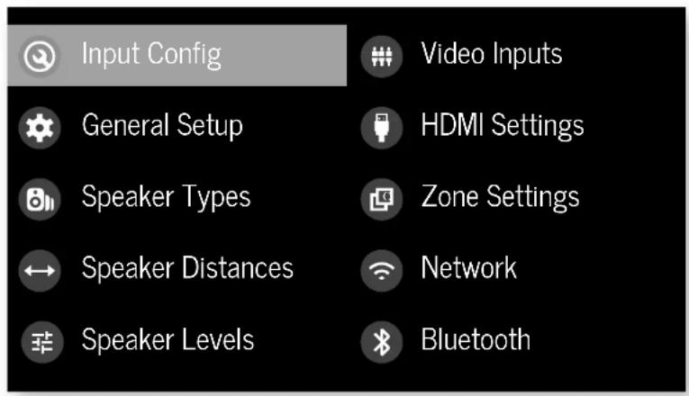
text_image
Input Config General Setup Speaker Types Speaker Distances Speaker Levels Video Inputs HDMI Settings Zone Settings Network BluetoothNavigating the setup menu
... using the remote control
The setup menu can be navigated by using the cursor (arrow) keys on the remote control. This is by far the easiest method.
- To enter the setup menu, press the MENALTON (which is located immediately under the navigation buttons).
- Use the ⚠️ and ⚼ keys to navigate up and down the main section headings.
-
Once you have the main section that you require highlighted, use the ⬆ key to enter the section.
-
Use the 🔒 and 🔒 keys to navigate up and down the section settings in the right-hand panel. Some settings may be previewed out. These are either for information only (e.g. incoming sampling frequency) or are not currently selectable. Scroll bars on the sides of the right-hand panel indicate your position in the settings list where there are more items than can be displayed at once.
- Pressingoklects a setting to change it, pressing OK again de-selects the setting.
- At any time, press the MENION to exit the menu. Any changes to settings are saved.
... using the keys on the front panel
The Receiver front panel controls can be used to configure the unit. Follow the instructions for using the remote control, in this case using INRITDOWN, for UNPUTER left INFO and MOORight.
Input Config.
The audio and video settings on this page of the Setup menu can be tailored specifically and independently for the currently selected input.
When a different input is selected on the input line, all the input-specific settings for that input are displayed below it. These settings are applied to the named Input only and are stored in memory and recalled each time the unit is powered up and whenever that input is selected.
Input - The currently selected input connectors to which the settings below relate.
Name The display name of the input. You can change the name of any input to more closely match your setup. For example, if you had two satellite receivers, you could connect the main receiver to the SAT audio and video input connectors and change the Name to 'SAT 1'. You could then connect the second satellite receiver to the WHO audio and video input connectors, but change the UID Name to 'SAT 2'. It is then clearer to users of your Receiver which inputs they wish to select when scrolling through.
Lip Sync - Each input can have its own setting to add a time delay between the audio and video signals to compensate for the sound and picture not being synchronised. This is normally required when video processing is used in the system for scaling or de-interlacing video. The range of lip sync delay is 0 to 250 milliseconds.
The lip sync adjustment can only correct for delayed videos. If the audio is late set lip sync to its minimum.
Mode—Sets the initial audio decode mode for stereo sources on this input.
☐ Last Mode recalls the last used setting for this input when a stereo source was applied. See section "Two-channel source modes" on page EN-35 for more information.
MCH. Mode - Sets the initial audio decode mode for multi-channel digital sources on this input.
☐ Last Mode recalls the last used setting for this in when a stereo source was applied. See section "Multi-channel source modes" on page EN-35 for more information.
Bass -
Treble -
These allow you to alter the bass and treble tone controls for all currently active speakers for each individual input. For example, if your PVR source sounds a little bass light, you can always correct for this by selecting PVR on the Input line at the top of this menu and ade 2 or 3c3 to the Bass control. Then, whenever the PVR input is selected, the bass is automatically posted for as long as that input is selected.
Room EQ - When the Dirac Live application is run and EQ filters are downloaded into one of the three slots available, this can be selected.
Not Calculated: (Information only) There are no EQ filters, so cannot be selected.
Project Name: Dirac Live Room EQ is applied to the current source and will display the name of the project from the Dirac Live application.
Off: Dirac Live Room HQ is not applied to the current source.
Input Trim - Sets the maximum analogue input signal level (sensitivity) on this input before the ADC (Analogue-to-Digital converted signal path clots. Options are 1, 2 and 4 volts RMS maximum input. The default is 2Vms maximum. For example, analogue sources with low output levels may benefit by choosing the TV maximum setting. This helps max rise signal to nose performance of the Receiver and also helps keep the various analogue sources sounding about the same level for any given Receiver volume control setting.
Dolby Audio Processing – Applies Dolby Audio Processing to the incoming audio.
Off: (default) Dolby Audio Processing is not applied to this input.
□ Movilitable for movie viewing.
□ Musictable for music listening.
□ Night: presses the audio to be more suitable for late night viewing or listening.
Stereo Mode - If you have configured your system to have a subwoofer, then you have the flexibility to choose how bass information is distributed between the front, left/right speakers and the subwoofer when listening to stereo (two channel only) analogue and digital sources. Choose the option which gives you the most sold, even sounding bass. If you are using a subwoofer for stereo, please also see Sun Stereo below to set the level of the subwoofer. For best results test with a setup disc or live programme material. This setting can be used to override your normal speaker settings in the Sokr Types menu whenever the Receiver plays stereo material. It is quite common to find that two channel stereo music listening is best done with a slightly different sub/speaker setting than for surround movies.
☐ As Spkr Types: When an analogue or digital stereo source is played, your normal speaker configuration (as in Spkr Types menu) is used to reproduce the signal.
☐ Left/Right: Full frequency stereo information. All audio is sent to the front left and right speakers only without any bass redirection. You can use this setting if you consider your front left/right speakers to be able to handle the full frequency range of music. If you have set your front left/right speaker size as Small in the Spkr Tyoes setup page, you may wish to use this option to override the setting to Large for stereo music listening, if you have full frequency range left/right speakers. It can often be beneficial to set full frequency range speakers so Small in the Spkr Tyoes setup page for use with movies, if you have a subwoofer in your system. Doing so may deliver more impact on movie soundtracks as subwoofer's are designed to handle reproduction of high bass content. However you may find that for stereo music a better overall result is obtained by not using the subwoofer and effectively treating the front left/right speakers as Large.
☐ Left/Right+Sub: Full frequency range stereo is fed to the front left and right speakers and extracted bass is sent to the subwoofer. In this case, the low frequency information is effectively duplicated.
Sat+Sub: Use this setting if you really do have Small satellite front left and right speakers, or if you prefer the overall sound of bass being handled by the subwoofer. Full bass management is used so that analogous and digital stereo sources are fed to the DSP where the bass is filtered off front left and right and redirected to the subwoofer.
NOTE: The Stereo Mode function is not available when using an analogue source in Stereo Direct mode.
Sub Stereo - If Left/Right+Sub or Sat+Sub is selected in Stereo Mode above, this setting adjusts the level of the subwoofer when the source is two channel stereo.
IMAX mode (AVR11, AVR21, AVR31, AV41) – Selects if IMAX mode is enabled from the incoming audio stream (auto) or forced on or off.
Auro-matic 3D (AVR11, AVR21, AVR31, AV41) – Selects the mode of the Auro-matic 3D upmixer.
☐ Small: Adjusts the upmixer for a small-sized room.
☐ Medium: (default) Adjusts the upmixer for a medium-sized room
□ Large: Adjusts the upmixer for a large-sized room.
□ Movie: Adjusts the upmixer for film material.
□ Speech: Adjusts the upmixer to focus on speech intelligibility.
Auro-matic 3D Strength (AVR11, AVR21, AVR31, AV41)
Adjusts the amount of unprocessed to processed signal when using the Auto-Matic 3D upmixer.
Audio Source - Selects the particular connection type for each input. The default is HDMI for inputs with an HDMI connection and Digital for inputs without an HDMI connection. This acting must be changed if another connection is used.
Select from the list the audio type you are using on this
source.
☐ HDMI: the unit is forced to use the HDMI audio input for this source.
Digital: the unit is forced to use the optical (TOSLINK) or coaxial (S/PDIF) digital audio input for this source
☐ Analogue: the unit is forced to use the analogue audio input for this source.
CD Direct Tums on/off the compressed audio detection mure delay. Your AVR mutes when it detects a change or break in a digital stream. This is intentional and prevents unwanted noise from being output from your speakers when using sources that change between multiple formats (e.g. a Blu ray player or TV Set Top Box). CD direct can be activated when used with a source that will only transmit a consistent format (e.g. a CD player with PCM audio). This will defeat the muting and prevent potential loss of the beginning of 'tracks where audio begins very promptly.
General Setup
General information and system controls.
Source Input - (Information only) The currently selected input to which the settings below relate.
Incoming Format (Information only) The format of the digital audio stream connected to this input, if present.
Incoming Sample Rate – (Information only) The sample rate of the digital audio stream connected to this input, if present.
Incoming Bit Rate (information only) The bit rate of the digital audio stream connected to this input, if present.
Dialnorm – (Information only) If a Dolby Digital audio stream is connected to this input, this is the Dialogue Normalisation setting requested by the stream.
Incoming Resolution - (Information only) Shows the incoming video resolution.
Audio Compression - Allows selection of compression which is ideal for late night listening. The compression effect increases the volume of the quiet passages and decreases the volume of the louder passages. Compression only applies to Delby/DTS soundtrack formats that support this function.
☐ Off: (default) no audio compression is applied.
☐ Medium: compression is applied so that loud portions of a soundtrack are reduced in level. Dolby
True HD stream is compressed automatically as set by the incoming stream.
☐ High: the maximum amount of dynamic range compression is applied, so that the difference between loud and quiet portions of a soundtrack is minimised.
This setting applies to all inputs when a relevant digital audio stream is detected. It is stored in memory and recalled each time the unit is powered up.
Balance - To alter the sound balance temporarily between front left and right speakers. You can alter the sound stage to either the left or the right by up to 60B. Note that it is not possible to shift the audio signal completely over to one channel. This function resets to equal left/right balance when the input is changed.
DTS Dialogue Control Sets the level of the dialogue channel in compatible DTS audio streams.
Maximum Volume - Limits the maximum volume setting the system can be turned up to in the main zone. This is a useful feature to prevent accidental overdriving of low power handling speakers (for example). It is stored in memory and recalled each time the unit is powered up.
Max On Volume – Limits the maximum volume the system operates in the main zone when it is switched on or comes out of Standby. The system comes on at this stored volume setting if the last used (possibly very loud) volume exceeds this value. It is stored in memory and recalled each time the unit is powered up.
Display on time - Sets the time that the front panel display remains illuminated after receiving a command. The default is always on.
Control – Enables or disables RS232 or IP (NET) control, a system that allows control from various third-party home automation systems. Note, only RS737 or IP control can be used, not both.
Power on - Determines how the unit powers on.
Stby: in Standby mode
On: On
□ Last state: Last state (default).
Language - Select the language for the setup menu English, French, German, Spanish, Dutch, Russian, Chinese.
Speaker Types
Settings for the types of loudspeaker you have connected in your configuration. These settings are applied to all audio inputs and are stored in memory and recalled each time the unit is powered up.
Front Left/Right -
Centre -
Surr. Left/Right -
Surr. Back L/R -
Height Front -
Height Back -
Here you set the type of speakers that you have connected to your Receiver:
□ Large: capable of full frequency range reproduction
☐ Small: not capable of full frequency range reproduction at the low frequency end
☐ None: speaker not present in your configuration
NOTE: It is not possible to set all speakers to Small unless there is a subwoofer in your speaker configuration. If you do not have a subwoofer, you will be forced to set your front speakers to Large.
NOTE: If there are only two ceiling height speakers connected, these need to be set as front, though can be placed either in front of, or above, the listening position.
Subwoofer - configures if the dedicated sub out terminals are used for a single subwoofer channel (using the two parallel outputs).
Channel 13 & 14 –
Channel 15 & 16 -
Configures the speaker positions that channels 13, 14, 15 & 16 are used for.
Height Type - configures the type of height, speakers ceiling mounted or Do by enabled.
Use Channels 6+7 for – If your main zone speaker set up does not include Surround Back Left and Right speakers, you can choose to use the Surround Back amplifier channels as
the Height 1 amplifiers, to Bi-Amp the Front Left and Right pair, or as a stereo power amplifier for Zone 7.
Filter Slope - Configures the filter slope used for bass management - 12dB, 24dB, 36dB, 48dB/octave.
Sub Gain - configures the output level trim for all outputs configured as subwoofers in -6dB steps from 0dB to -30dB.
Speaker Distances
Calibration settings for the distances between the loudspeakers and the listening position.
NOTE: Speakers that are not present in your configuration will be greyed out.
If Dirac Live is used, these settings will be shown in time (mS) and not distance.
These settings are applied to all audio inputs and are stored in memory and recalled each time the unit is powered up.
Units - Select whether you wish to measure distances in imperial or metric units.
Front Left -
Centre -
Front Right –
Surr. Right –
Surr. Back Right –
Surr. Back Left -
Surr. Left -
Left Top Front -
Right Top Front -
Left Top Back -
Right Top Back –
Subwoofer
Channel 13 -
Channel 14 -
Channel 15 -
Channel 16 -
As described in "Essential Setup" on page EN-28, measure the distance from each loudspeaker in your system to your ear in the main listening position and enter the values. This allows the Receiver to calculate the correct relative delay for each
loudspeaker.
Speaker Levels
Calibration settings for the test noise signal level through the loudspeakers and measured at the listening position.
NOTE: Speakers that are not present in your configuration will be greyed out.
These settings are applied to all audio inputs and are stored in memory and recalled each time the unit is powered up.
Test Tone - selects the internal test tone generator or allows the use of an external test tone from the currently selected HDMI input (e.g. played from a BD).
Front Left -
Centre
Front Right -
Surr. Right –
Surr. Back Right –
Surr. Back Left -
Surr. Left -
Left Top Front –
Right Top Front -
Left Top Back -
Right Top Back -
Subwoofer –
Channel 13 –
Channel 14 –
Channel 15 –
Channel 16 –
Use the 🔒 and ▼ navigation buttons on the remote control to select the relevant speaker. Press ⚫ to enable/ disable the calibration noise and the 🔒 and ▼ navigation buttons to adjust the noise level from each speaker.
As described in "Essential Setup" on page EN 28, adjust the
level of the test noise from each speaker so that an SPL meter at the listening position measures 75dB SPL.
Video Inputs
Settings to optionally assign a video source to each of the normally audio-only inputs.
These settings are stored in memory and recalled each time the unit is powered up.
Video Input CD -
Video Input Aux –
Video Input FM -
Video Input DAB –
Video Input Net -
Video Input BT -
The default for each of the audio inputs is 'None'. You could, however, associate 'Sat' video with FM or Digital Radio audio to receive radio commentary of a sports game with pictures from sale-lite coverage, for example.
HDMI Settings
The settings in this menu control the output resolution from the video processor in the Receiver. These settings are applied to all video inputs and are stored in memory and recalled each time the unit is powered up.
Zone 1 OSD – Selects whether the main zone pop-up OSD messages are On or Off. It is stored in memory and recalled each time the unit is powered up.
☐ When On, all user adjustments that are made during the general use of the Receiver are displayed on screen as well as the front panel display. This includes the adjustment of volume, subwoofer level, lip sync, tone controls, etc. It is stored in memory and recalled each time the unit is powered up.
When Off, the above user adjustments will not appear on screen, only on the front panel display. This leaves the picture on your display device clear of pop-up text. However, regardless of this setting the Setup menus are always displayed on screen.
Zone 1 Out - This setting controls the output for zone 1 from either output 1, output 2 or both.
Zone 1 Lipsync (Information only) Displays how much tip sync is automatically applied to the HDMI output to
compensate for video processing delays in the attached display device. Not all display devices support this function.
HDMI Audio to TV - this setting controls the audio being sent direct to the TV.
HDMI Bypass & IP – This setting controls the functionality of HDMI bypass & IP control while in standby. Selecting "Low Power" (default) will mean that IP control (network) and HDMI bypass are disabled. Selecting "HDMI & IP On" means that IP Control (network) & HDMI bypass is enabled.
HDMI Bypass Source – Selects which input is used for HDMI bypass function, either a specific input or the last input used.
CEC Control Selects if CEC control is enabled on output 1. eARC Control – This setting enables/disables volume control from the display.
TV Audio - This setting enables/disables auto-switching to eARC audio from the display.
Power Off Control - This setting enables/disables auto-power control from other CEC enable devices.
Zone Settings (AVR21, AVR31, AV41)
Lists the volume and control settings for Zone 2. These settings are applied to all audio inputs and are stored in memory and recalled each time the unit is powered up.
Z2 Input - Selects the input to be routed to Zone 7. The default is 'Follow Z1', i.e. the same source as currently selected in Zone 1.
Zone 2 Status – Selects if Zone 2 is in Standby or On.
Zone 2 Volume – The current volume in Zone 2.
Zone 2 Max. Vol - Limits the maximum volume setting the system can be turned up to in the Zone 2. This is a useful feature to prevent accidental overdriving of low power-handling speakers, for example.
Zone 2 Fixed Vol - The Zone 2 volume control can be locked at the current value for use with an external amplifier with its own volume control in Zone 2.
Zone 2 Max On Vol - Limits the maximum volume the system operates in the Zone 2 when it is switched on or comes out of Standby. The system comes on at this volume if the last used (possibly very loud) volume exceeds this value.
Connecting to a Network
Network
The Receiver is fitted with a network audio client which is capable of AirPlay 7 and Chromecast built-in as well as stored music on a network storage device such as a PC, or on NAS drive.
The wireless network is configured using the Apple AirPlay setup or the Google Home app.
SSID (Information only) Displays the SSID the receiver is currently connected to, "wired" if a wired connection is used, or "not connected" if no connection is present.
IP Address (Information only) IP address assigned by the DHCP server, or if not using DHCP, the IP address you have assigned to the Receiver for your network.
MAC address – (Information only); The unique address of the network card in your Receiver.
Friendly name – (information only) The network "friendly name" of your Receiver.
Bluetooth
The Receiver is fitted with a Bluetooth audio input.
Pair Device – Makes the Receiver discoverable by Bluetooth devices.
Clear Paired Device List – Clears the Receiver's list of paired Bluetooth devices.
Paired Devices = Displays a list of the devices paired with the Receiver.
In order to use the AirPlay and Chromecast built-in functionality of the Receiver you will need to connect it to your home network via a wireless or wired connection.
The following sections detail how to do this.
Note: Before attempting to setup a wireless connection ensure the supplied wireless antennas are fitted to the antenna socket on the rear of the Receiver.
Home Automation Control
When connected to a network the Receiver can be controlled and monitored remotely using dedicated home automation software.
The same controls are also available via the RS232 input. Various third-party systems are available providing sophisticated control over all your entertainment devices. Contact your dealer or installer for details. The technical details of the remote control protocol are available upon request, by contacting Arcarn at luxurysupport@harman.com.
For details of the available controls please refer to the control document which can be found at www.orcam.co.uk for further information.
AirPlay Setup
Wired Connection
Connect an ethernet cable to the Receiver.
To listen to audio via AirPlay on your Receiver, ensure your Apple device is connected to the same network as the Receiver and simply select the Receiver as the AirPlay audio playback device.
Note: The Receiver will appear as ARCAM modelname-xoxoox in the AirPlay speaker menu, where xoxoox is the last 6 digits of the units MAC address.
Wireless Connection
Ensure your Apple device is connected to the wireless network you wish to connect the Receiver to.
Open the Wi-Fi settings menu on the Apple device and select the Receiver from the "Sci up new AirPlay speaker" menu. Follow the Instructions on screen. To listen to audio via AirPlay on your Receiver, ensure your Apple device is connected to the same network as the Receiver and simply select the Receiver as the AirPlay audio playback device.
Note: The Receiver will appear as ARCAM modelname-xxxxx in the AirPlay speaker setup menu, where xxxxx is the last 6 digits of the units MAC address.
Chromecast built-in Setup
Wired Connection
Connect an ethernet cable to the Receiver.
Wired & Wireless Connection
Download and open the Google Home application.


You should be prompted that there is a device available for setup. If not simply tap "Add" followed by "Setup a Device". Select the Receiver and follow the instructions on screen.
To listen to cast audio from any supported application on your Receiver, ensure your device is connected to the same network as the Receiver. Tap the Chromecast built in icon from within the application and select the Receiver as the playback device.
Note: The Receiver will appear as modelname xxxxx in the setup menu, where xxxxx is the last 6 digits of the units MAC address.
Spotify Connect
Use your phone, tablet or computer as a remote control for Spotify.
Go to spotify.com/connect to learn how.
Introduction
Your Receiver receiver provides all the key decoding and processing modes for analogue and digital signals, including the latest high definition audio formats over HDMI.
Modes for digital sources
Digital recordings are usually encoded to include information about their format type. The Receiver detects automatically the relevant format in a digital signal such as Dolby Atmos, TrueHD, Dolby Digital Plus, DTSX, DTS-HD Master Audio, Aero 3D, Dolby Digital, or DTS – and switches in the appropriate decoding.
Modes for analogue sources
Analogue recordings do not contain information about their encoding formats, so the desired mode - such as Dolby Surround - needs to be selected manually.
Mode memory
Dolby Digital or DTS audio (including the high definition formats) can be output in two mix modes, selected using the MODE button:
□ Surround (e.g., five main channels plus a subwoo for a 5.1 source)
□ Stereo downmix.
Two-channel audio, regardless of whether it is analogue or digital can also be output in two mix modes, selected using the mode button;
- Surround (e.g., Dolby Surround, DTS Neural X, etc.) - Stereo.
The Receiver stores the settings for each source. Thus the decoding mode for the following groups of source material can be stored independently:
☐ Dolby Digital (multi-channel) and D15 source mate ☐ Two channel Dolby, PCM or Analogue source mate
Two-channel source modes
The following decoding and surround modes are for treating multi-channel stereo modes from 2-channel sources. They are available on the Receiver for standard and high definition Dolby Digital 7.0, DTS 7.0, PCM or analogue sources:
Stereo -
16 Channel Stereo -
Dolby Surround -
Dolby Virtual Height -
DTS Neural:X -
DTS Virtual:X -
Auro-matic 3D (AVR11, AVR21, AVR31, AV41)
Stereo
In this mode the Receiver works as a conventional high quality audio amplifier. Note that if the subwoofer is enabled in stereo mode, then some processing of the signal is carried out.
□ Stereo Direct: this achieves the most direct signal path if an analogue connection is present.
16 Channel Stereo: this produces an output from all speakers by copying the left output to all left speakers and the right output to all right speakers. The centre speaker outputs a mix of left and right.
Dolby Surround
Delloy Surround allows the Receiver to derive up to 16 outputs from a two or multi-channel source to take better advantage of a Iampifiers and sneakers in your setup.
Dolby Virtual Height
Dolloy Virtual Height creates an immersive audio experience by virtualising height content over traditional speaker configurations without the need for height speakers. Note this mode is NOT available if height speakers are selected.
DTS Neural:X
DIS NeuralX is an advanced up-mixer that renders up to 17. A channels of immersive audio from nearly any lower channel count centers.
DTS Virtual:X
DTS VirtualX creates an immersive audio experience by virtualising height content over traditional speaker configurations without the need for height speakers. Note - this mode is NOT available if height speakers are selected.
Auro-matic 3D (AVR11, AVR21, AVR31, AV41)
Aromatic 3D creates an immersive audio experience by treating additional channels from the incoming audio to match the available output channels, enhancing the listening experience.
Multi-channel source modes
Digital multi-channel source material is normally provided as '5.1 audio'. The '5.1 channels' comprise of left, centre and right front speakers, two surround speakers and a low frequency effects (.LFE) channel. Since the LFE channel is not a full range channel, it is referred to as '1'.
Surround systems decode and reproduce the 5'- channels directly. The DIS-FS matrix enhanced decoding system creates one extra rear channel from information buried in the two surround signals of the 5.1 source. The ES enhanced system is sometimes referred to as a 6.1 system. This extra surround back channel is normally reproduced through two separate loudspeakers, creating a 7.1 system.
DTS-ES discrete is a true '6.1' source, with six discretely encoded channels, plus the '1'-1'-E channel.
Delby Digital Plus, Delby True-ID, Delby Almos, DTS-X, DTS-HD, Auto 3D are high-resolution surround formats found on Blu-Ray discs
Decoding modes
The modes given in the following table are available for multi channel digital sources.
Special modes such as DTS-ES 6.1 discrete, Dolby Digital Plus, Dolby TrueHD, Dolby Atmos, DTS-X, DTS HD and IMAX® ENHANCED, Auro 3D are only available from the correct source material.
High resolution audio sources
| Dolby Atmos | Do by Atmos content is mixed as audio objects instead of traditional channels, so can take full advantage of the number and placement of your speakers. |
| Dolby TrueHD | Provides up to 7.1 full channels at 96kHz, 24bit resolution, with potentially no losses in the compression process. Data rates can be up to 18Mbps. |
| Dolby Digital Plus | Provides up to 7.1 discrete channels of audio with less compression than traditional Dolby Digital encoding. Data rates can be up to 6Mbps. |
| DTS-HD Master Audio | Provides up to 7.1 full channels at 96kHz, 24bit resolution, with potentially no losses in the compression process. Data rates can be up to 24.5Mbps. |
| DTSX® DTSX is a decoder package that renders immersive content which has been encoded with DTSX encoding. DTSX content consists of audio objects or a combination of audio channels and objects. The DTSX decoder package also plays back legacy DTS formats including DTS HD Master Audio lossless and lossy streams.Supports greater than 7.1 channel output configurations (including height speakers);Provides "Dialogue Control" so consumers can adjust the sound to their preference or the listening environment.Remaps any DTS content to any speaker layoutSupports Blu-ray Disc (3D), DVD and streaming media formats, and legacy stream's up to 196kHz.Includes NeuralX, the latest upmixing/downmixing technology from DTS. | |
| IMAX ENHANCHD(AVR11, AVR21, AVR31, AV41) | IMAX® Enhanced produce meet the highest level of standards, ensuring the best color, contrast, clarity and sound on the market. These are products endorsed by IMAX to fully deliver the most immersive at-home entertainment experience and leverage the full quality and scale of IMAX Enhanced content. The IMAX Enhanced program introduces a new standard in home entertainment. |
| AURO 3D(AVR11, AVR21, AVR31, AV41) | AURO 3D is a decoder package that renders the audio at three levels - ear level, height level and the centre height level, creating an immersive sphere of audio. |
For Dolby Digital sources
| Dolby Digital 5.1 | Dolby Digital 5.1 sources deliver sound with five discrete full range channels, left, corner, right, surround left, surround right, plus LTE channels. |
| Dolby Digital Stereo Downmix Provides a stereo downmix of the source material for use with headphones. | |
| Dolby Digital 5.1 + Dolby Surround | This mode is used to derive information for the individual surround back channels from the surround channels, using the Dolby Surround decoder. |
| For DTS sources | |
| DTS 5.1 Less common than the Dolby | Digital format, but generally recognised within the audio industry as being at superior sound quality. DTS 5.1 delivers surround sound with five full range channels plus an LTE channel. |
| DTS 5.1 Stereo Downmix Provides a stereo downmix of the source material for use with headphones. | |
| DTS-E5 6.1 Matrix | This is a 6.1 channel format based on DTS 5.1. It has the sixth channel matrix encoded into the surround left and surround right channels. The sixth channel is a surround centre channel and is directed to the surround back left and surround back right speakers. |
| DTS-E5 6.1 Discrete | This is a two discrete 6.1 channel sound format. DTS-E5 discrete mode operates only on sources with DTS-E5 6.1 discrete audio encoding. |
| DTS96/24 Provides up to 5.1 channels | Is of audio at 96kHz, 240t resolution for superior sound quality compared to standards DTS 5.1 |
Tuner Operation
The Receiver is fitted with an TM/DA0/DA0+ (digital radio) tuned. DAB broadcasts are not available in all locations.
This section deals with tuner operation, for information on setting up the tuner and installing aerials, see page EN-13.
The front panel will also give the same information, pressing the INFO will cycle through the various items of information.
FM
Processing mode (default)
□ Radiotext (if available)
□ Programme type (i² available)
□ Signal strength
DAB
Processing mode (default)
□ Radiotext (if available)
Programme type
Signal quality
11 Bit rate of transmission
Tuning/Channel Selection
When switching to the internal TUNER source, the Receiver enters the last used tuner band, be it FM or DAB. Repeatedly pressing RADIOs through the available tuner bands on your Receiver.
FM analogue radio
Frequency tuning on HV radio is performed using the 🔒 and 🔒 buttons on the remote control in TUN device mode. Individual presses move the frequency down and up one step if you press and hold either of the tuning buttons for two seconds, the tuned scars to the next strong signal. You can stop a scan at any time by pressing one of the tuning buttons again.
In Europe, the internal FM radio is capable of receiving RDS (Radio Data System) radiocext signals that are transmitted on some stations. The RDS information typically includes the radio station name, the music or speech genre as well as additional information related to the current programme. On music stations this is often information on the currently playing track.
DAB digital radio
DigitalAudioBroadcasting(DAB)raoisbecomingmorewidely available. See www.worlddab.org/country_information for information on DAB availability.
You will need to scan for available stations before being able to listen to them.
To scan for DAB stations, first select the DAB tuner then press and hold until the display indicates scanning has started. The Receiver will then scan all the DAB radio frequencies and compile a list of the stations that are available.
When the scan is complete, you can scroll through the station list using the ⏻ and ⏻ buttons on the remote control. To listen to the currently displayed station press the ⏻. If you do not press ⏻ within two seconds, the display will revert to displaying the currently playing station.
Saving and selecting Presets
Preset selection uses the ▲ and ▼ keys on the remote to browse and Ⓞ to select the preset when the remote is in TUN device mode.
Up to 50 presets can be stored and these can be from any
band, for example Preset 1 could be an TM station, preset two a DAE station, etc. Pressing the OK key causes the next available preset number to be displayed, then pressing the OK key again stores the current frequency/channel in that preset. If a different preset number is required, press the ▲ and ▼ keys until the desired number is displayed before pressing the OK key for a second time.
Deleting Presets
When in turner browse mode (using ▲ and ▼ to scroll through the presets), the yellow button on the remote is used to delete the currently highlighted (but not playing) station or frequency.
Troubleshooting
| Problem Check the following | |
| There are no lights on the unit | ☐ The power cord is plugged into the receiver and the mains socket it is plugged into is switched on.☐ The power button is pressed in.☐ If a red led is present, the receiver is in standby mode. Press any button on the front panel or the standby button on the remote control. |
| The unit responds erratically or not at all to the remote control | ☐ There are fresh batteries in the remote control.☐ The front panel window is visible and you are pointing the remote control towards it. |
| The front panel display is blank | ☐ The display hasn't been turned off. Press the DISPLAY button on the front panel or remote control. |
| No picture is being produced | ☐ Your viewing device is turned on and switched to display your receiver. Test by pressing the MEMotion on the receiver or on the remote and look for the main menu screen on your display device.☐ The correct video input is selected on the receiver.☐ The video source is on, is operating normally, and is in 'play' mode if appropriate. |
| There are bright edges or 'ghosts' on the picture | ☐ Ensure the 'sharpness' control on your display device is switched off or set to near minimum.☐ For hdmI connections, try using a shorter cable or alternatively a different brand. |
| No sound is produced | ☐ The correct input has been selected.☐ The 'audio source' has been set correctly in the 'input config' Menu☐ The source equipment is on, is operating normally and is in 'play' mode if appropriate.☐ The volume is turned up to a reasonable level and the receiver is not in mute mode. |
| The sound is poor or distorted | ☐ You have not excessively increased the input sensitivity (i.e. Reduced the maximum input signal voltage) in the input config. Menu if an analogue input is being used.☐ You have selected the correct size of speakers to suit your system in the setup menu. |
| Problem Check the following | |
| Sound only comes from some of the speakers. | ☐ You have an appropriate surround source selected and playing.☐ The bd/dvd disc is encoded in the appropriate format, and the correct format has been selected in the disc start menu of the bo player (if applicable).☐ The bd/dvd player has been set to output 'bitstream' audio on the digital output.☐ The display window indicates that the disc you are playing is a multichannel recording (you may need to press the INIF@y several times until you get to the 'incoming format' display).☐ All the speakers are correctly connected to the speaker terminals and are secure.☐ You have not selected 'stereo' as the decoding mode.☐ Your speaker balance is correct.☐ You have configured the receiver to include all the speakers in your system. |
| Unable to select Dolby or DIS decoding modes | ☐ The receiver can only apply dolby and dis decoding to sources which have been encoded in the same format.☐ Check that:☐ Digital source is selected and connected.☐ The source is playing appropriately encoded material.☐ The bd/dvd disc is encoded in the appropriate format and that the correct format has been selected in the disc start menu of the bd player (if applicable).☐ The bd/dvd player has been set to output 'bitstream' audio on the digital output. |
| When playing a Dolloy BDV/DVD, the AV selects Dollay Surround | ☐ You have a digital connection from your bo/dvd player.☐ Sometimes dolby od/dvd discs contain material at either the beginning or the end of the main movie that is not in full 5.1 format, but in two channel. |
| Hum on the analogue input | ☐ All cables are making a good connection. If necessary withdraw the cable from the connector and plug it fully in again (turn the power off before doing this).☐ The connections inside the source cable connector are not broken or badly soldered.☐ If the num originates only when one particular source component is connected, that an aerial cable, or dish connection to this source is ground isolated. Contact your installation contractor. |
Problem Check the following
| There is radio or television reception interference. | □ Where the interference is coming from. Switch off each source component in turn, then any other equipment. Most electronic equipment does generate low levels of interference.□ Try rearranging cabling from the nuisance source away from other cabling.□ Ensure that the cabling used is high quality, specified for its purpose, and is properly screened.□ If the problem persists, contact your dealer. |
| The source switching changes randomly or freezes on one source | □ There are no static or impulse interference problems caused by nearby power equipment switching, e.g., heating or air conditioning control. Switch the receiver off, wait ten seconds, then switch it on again to clear an operating problem. Contact your installer if the problem returns or persists.□ There is no direct sunlight shining on the infra-red detector behind the front panel display. |
| Volume is always too loud when I turn on | □ The 'max on volume' settling is not set too high. |
| If files on a NAS drive cannot be played | □ The files are in a compatible format.□ The computer is connected via a network and not usb - the receiver usb port cannot be used for a direct connection to a computer |
| If you cannot connect to a wired network | □ The ethernet cable you are using is correctly connected between the receiver and the network hardware.□ The network is set up for fixed ip addressing and you have the receiver set to use dhcp.□ The network is set up for dhcp and you have the receiver set to use fixed ip addressing. |
| If you cannot connect to a favourite internet radio station | □ The station is still broadcasting or is not congested - try again later. |
| If the internet radio station sound quality is poor or broken | □ The radio station has a low bit rate (use the INFO key to find this).□ The network is not slow or congested. |
Specifications
AV41
| Stereo line inputs | |
| Maximum input | 4.5V rms |
| Nominal sensitivity | 1V, 2V, 4V (user adjustable) |
| Input impedance | 47kΩ |
| Signal/noise ratio (A-wid ref 100W)normal/stereo direct | 93dB/110dB |
| Frequency response | 20Hz 20kHz ± 0.1dB |
| Preamplifier outputs | |
| Nominal output level (single-ended/balanced) | 1V RMS/2V RMS |
| Output impedance | 560Ω |
| THD+N (20Hz—20kHz) | -100c3 |
| Headphone output | |
| Maximum output level into 32Ω | 5Wrms |
| Output impedance | <100Ω |
| General | |
| Mains voltage | 110–120V or 220–240V, 50–60Vz |
| Power consumption (maximum) | 50W (thermal dissipation approx. 170 61.1/hour) |
| Power consumption (idle, typical) | 40W (thermal dissipation approx. 170 61.1/hour) |
| Power consumption (standby) | <0.5W |
| Dimensions W x D(including speaker terminals) x H (including feet) | 433 x 425 x 171 mm |
| Weight (net) | 10.6kg |
| Weight (packed) | 13.9kg |
| Supplied accessories | Mains leadRemote control with 2 x AAA batteriesManualDAB/TmA aerial3 x WiFi/Bluetooth antennasCalibration microphoneUSB cable |
| E&OE | |
| NOTE: All specification values are typical unless otherwise stated. | |
Continual improvement policy: Arcam has a policy of continual improvement for its products. This means that designs and specifications are subject to change without notice.
AVR31
| Continuous power output, per channel, 8Ω/4Ω | |
| 2 channels driven, 20Hz - 20kHz, <0.07% I-HI> | 120W/700W |
| 2 channels driven, 1kHz, 0.7% I-HI> | 140W/770W |
| 7 channels driven, 1kHz, 0.7% I-HI> | 100W/180W |
| Residual noise & hum (A wtd) | <0.15mV |
| Stereo line Inputs | |
| Maximum input | 4.5V rms |
| Nomina sensitivity | 1V, 2V, 4V (user adjustable) |
| Input impedance | 4/8Ω |
| Signal/noise ratio (A-wto ref 100W) norma/stereo direct | 93dB/110dB |
| Frequency response | 20Hz - 20kHz ± 0.1dB |
| Preamplifier outputs | |
| Nomina output level | 1V RMS |
| Output impedance | 560Ω |
| TIID-N (20I Hz - 20N Hz) | -100dB |
| Headphone output | |
| Maximum output level into 32Ω | 5Vrms |
| Output impedance | <100Ω |
| General | |
| Mains voltage | 110-120V or 220-240V, 50-60Hz |
| Power consumption (maximum) | 1.5kW (Thermal dissipation approx. 5200 BTU/hour) |
| Power consumption (idle, typical) | 100W (Thermal dissipation approx. 340 BTU/hour) |
| Power consumption (standby) | <0.5W |
| Dimensions W x D(including speaker terminals) x H (including feet) | 433 x 425 x 171mm |
| Weight (net) | 18.1kg |
| Weight (packed) | 21.4kg |
| Supplied accessories | Mains loadRemote control with 2 x AAA batteriesManualDAB/HM aerial3 x WIH/Bluetooth antennasCalibration microphoneUSB cable |
| E&OE | |
| NOTE: All specification values are typical unless otherwise stated. | |
AVR21
| Continuous power output, per channel, 8Ω/4Ω | |
| 2 channels driven, 20Hz - 20kHz, <0.02% 1HD | 11CW/175W |
| 2 channels driven, 1kHz, 0.2% 1HD | 175W/190W |
| 7 channels driven, 1kHz, 0.2% 1HD | 90W/110W |
| Residual noise & hum (A width) | <0.15mm |
| Stereo line Inputs | |
| Maximum input | 4.5V rms |
| Nominal sensitivity | 1V, 2V, 4V (user adjustable) |
| Input impedance | 47kΩ |
| Signal/noise ratio (A-wtd ref 100W) normal/stereo direct | 93dB/110dB |
| Frequency response | 20Hz - 20kHz ± 0.263 |
| Preamplifier outputs | |
| Nominal output level | 1V RMS |
| Output impedance | 560Ω |
| TI ID+N (20Hz - 20kHz) | 100dB |
| Headphone output | |
| Maximum output level into 32Ω | 5V rms |
| Output impedance | <100Ω |
| General | |
| Mains voltage | 110-120V or 220-240V, 50-60Hz |
| Power consumption (maximum) | 1.5KW (Thermal dissipation approx. 5200 STU/hour) |
| Power consumption (idle, typical) | 100W (Thermal dissipation approx. 340 STU/hour) |
| Power consumption (standoy) | <0.5W |
| Dimensions W x D(including speaker termina s) x H (including feet) | 433 x 425 x 171 mm |
| Weight (net) | 16.6kg |
| Weight (packed) | 19.9kg |
| Supplied accessories | Mairs loadRemote control with 2 x AAA batteriesManualDAB/+M acrial3 x WiFi/Bluetooth antennasCalibration microphoneUSB cable |
| E&OE | |
| NOTE: All specification values are typical unless otherwise stated. | |
AVR11
| Continuous power output, per channel, 8Ω/4Ω | |
| 7 channels driven, 20Hz - 20kHz, <0.07% THD | 80W/100W |
| 7 channels driven, 1kHz, 0.2% THD | 85W/120W |
| 7 channels driven, 1kHz, 0.2% THD | 60W/85W |
| Residual noise & hum (A wild) | <0.15mV |
| Stereo line Inputs | |
| Maximum input | 4.5V rms |
| Nominal sensitivity | IV, 2V, 4V (user adjustable) |
| Input impedance | 47kΩ |
| Signa/noise ratio (A-wtd ref 100W, normal/stereo direct | 93oS/110oB |
| Frequency response | 20Hz 20kHz ± 0.2dB |
| Preamplifier outputs | |
| Nominal output level | 0.8V RMS |
| Output impedance | 560Ω |
| T1D+N (20 Hz - 20kHz) | -100oS |
| Headphone output | |
| Maximum output level into 32Ω | 5Vrms |
| Output impedance | <100Ω |
| General | |
| Mains voltage | 110-120V or 220-240V, 50-60Hz |
| Power consumption (maximum) | 1.5KW (Thermal dissipation approx. 5200 BTU/hour) |
| Power consumption (idle, typical) | 90W (Thermal dissipation approx. 340 BTU/hour) |
| Power consumption (standby) | <0.5W |
| Dimensions W x D(including speaker terminals) x H (including feet) | 433 x 425 x 171mm |
| Weight (net) | 16.5kg |
| Weight (packed) | 19.8kg |
| Supplied accessories | Mains loadRemote control with 2 x AAA batteriesManualDA3/F-M acrial3 x WiH/Bluetooth anonmaxCalibration microphoneUSB cable |
| E&OE | |
| NOTE: All specification values are cyclical unless otherwise stated. | |
Worldwide Guarantee
This entitles you to have the unit repair red free of charge, during the first five years after purchase, provided that it was originally purchased from an authorised Arcam dealer. The Arcam dealer is responsible for all after-sales service. The manufacturer can take no responsibility for defects arising from accident, misuse, abuse, wear and tear, neglect or through unauthorised adjustment and/or repair, neither can they accept responsibility for damage or loss occurring during transit to or from the person claiming under the guarantee.
The warranty covers:
Parts (excluding disc drive) and labour costs for five years from the purchase date (see below for additional terms and conditions). After five years you must pay for both parts and labour costs.
Disc drives (of any type) are covered under this warranty for three years from the purchase date.
The warranty does not cover battery replacement at any time.
The warranty does not cover transportation costs at any time.
Claims under guarantee
This equipment should be packed in the original packing and returned to the dealer from whom it was purchased. It should be sent, carriage prepaid by a reputable carrier – not by post. No responsibility can be accepted for the unit whilst in transit to the dealer or distributor and customers are therefore advised to insure the unit against loss or damage whilst in transit.
For further details contact Arcam at luxurysupport@harman.com
Problems?
If your Arcam dealer is unable to answer any query regarding this or any other Arcam product please contact Arcam Customer Support at the above address and we will do our best to help you.
On-line registration
You can register your product online at www.arcam.co.uk.
ARCAM | HDA
AMPLIFICATEURS AVR D'AMBIANCE
AV41/AVR31/AVR21/AVR11
Bienvenue
SAT, PVR, BD, CD, STB, AV
STB, JEU, AV, BD, PVR, CD
Z2 IR (AVR21, AVR31, AV41)
text_image
SPX/ER OUTPUTS + SP PR C R SI - SP PR C FL SL C D E F G H I J K L M N O P Q R S T U V W X Y ZL Cinémaitale for movie viewing
Musiquelable for music listening
Configuration Chromecast built-in
Connexion par fil
Auro-Matic 3D (AVR11, AVR21, AVR31, AV41) -
Stéréo
Auro-Matic 3D (AVR11, AVR21, AVR31, AV41) –
Modes sources multicanaux
AV41/AVR31/AVR21/AVR11
DE
Willkommen
MQA (Measure Quality Authenticated).
OUTPUT (Zone2 - AVR21, AVR31, AV41)
Digitale Audioanschlüsse

SAT, PVR, BD, CD, STB, AV
Zone 2 Anschlüsse (AVR21, AVR31, AV41)

STB, GAME, AV, BD, PVR, CD
Z2 IR (AVR21, AVR31, AV41)
Auro-Matic 3D (AVR11, AVR21, AVR31, AV41) -
Stereo
Auro-Matic 3D (AVR11, AVR21, AVR31, AV41)
AV41/AVR31/AVR21/AVR11
NL
Welkom
MQA (Measure Quality Authenticated).
PVR, UHD, BD, SAT, AV, SPEL, STB
SAT, PVR, BD, CD, STB, AV
STB, GAME, AV, BD, PVR, CD
Z2 IR (AVR21, AVR31, AV41)
Verborgen commando's
Chromecast built-in-instelling
Draadaansluiting
Tweekanaals bronmodi
Auro-Matic 3D (AVR11, AVR21, AVR31, AV41) -
Stereo
Auro-Matic 3D (AVR11, AVR21, AVR31, AV41)
AV41/AVR31/AVR21/AVR11
Bienvenido
PVR, UHD, BD, SAT, AV, GAME, STB
SALIDA (Zone2 - AVR21, AVR31, AV41)
SAT, PVR, BD, CD, STB, AV
STB, GAME, AV, BD, PVR, CD
Z2 IR (AVR21, AVR31, AV41)
text_image
SFLASIL CULTURE + SR FR C FL SL - SR FR C FL SL CLASS NAMEAuro-Matic 3D (AVR11, AVR21, AVR31, AV41) –
Estéreo
Auro-Matic 3D (AVR11, AVR21, AVR31, AV41)
AV41/AVR31/AVR21/AVR11
Приветствие
В boile boile boile boile boile boile boile boile boile boile boile boile boile boile boile boile boile boile boile boile boile boile boile boile boile boile boile boile
PVR, UHD, BD, SAT, AV, GAME, STB
SAT, PVR, BD, CD, STB, AV
STB, ИГРА, AV, BD, PVR, CD
Z2 IR (AVR21, AVR31, AV41)
text_image
SFLASIL CULTURE SR FR C FL SL + - FR R C FL SL CLASS WARSAuro-Matic 3D (AVR11, AVR21, AVR31, AV41) -
Стерео
Auro-Matic 3D (AVR11, AVR21, AVR31, AV41)
AV41/AVR31/AVR21/AVR11
Benvenuto
PVR, UHD, BD, SAT, AV, GAME, STB
USCITA (Zone2 - AVR21, AVR31, AV41)
SAT, PVR, BD, CD, STB, AV
STB, GAME, AV, BD, PVR, CD
Z2 IR (AVR21, AVR31, AV41)
3D Auro-Matic (AVR11, AVR21, AVR31, AV41) -
Stereo
3D Auro-Matic (AVR11, AVR21, AVR31, AV41)
AV41/AVR31/AVR21/AVR11
CN
安全

输出 (Zone2 - AVR21, AVR31, AV41)
Z2 IR (AVR21, AVR31, AV41)
text_image
SPEAKER OUTPUTS + SR PR C R SL - SR PR C RL SL CLOSED WITHChromecast built-in 设置
无线连接
将以太网线缆连接到接收器。
无线连接
Auro-matic 3D (AVR11, AVR21, AVR31, AV41) -
立体声
Auro-matic 3D (AVR11, AVR21, AVR31, AV41)
调制方案:FHSS (Frequency-Hopping Spread Spectrum)
AV41/AVR31/AVR21/AVR11
환영합니다
Arcam HDA 수신기를
구입해 수서서 갑사합니다
PVR, UHD, BD, SAT, AV, GAME, STB
SAT, PVR, BD, CD, STB, AV
STB, GAME, AV, BD, PVR, CD
text_image
BCATE OUTPUT ARCAM BD/SAT CD라디오 및 무선 오디오 커넥터
DAB/FM 커넥터
Z2 IR (AVR21, AVR31, AV41)
text_image
SFLAXLE COUPE18 + SR PR C FL SL - SR PR C IL SL CLASS 2005□ Last state: -시막상터(부값)
Chromecast built-in 설정
유선 연결
오로매틱 3D (AVR11, AVR21, AVR31, AV41) -
스테레오
오로매틱 3D (AVR11, AVR21, AVR31, AV41)
THE WEST WING, STIRLING HOUSE
WATERBEACH, CAMBRIDGESHIRE, CB25 9PB
+44 (0) 1223 203200SH321 ISSUE A