Roomside BELS8 - Fan BROAN - Free user manual and instructions
Find the device manual for free Roomside BELS8 BROAN in PDF.

| Brand | Broan |
| Model | Roomside BELS8 |
| Category | Fan with light |
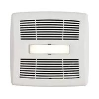
| Product type | Ducted ceiling fan with humidity sensor and LED light |
| Power supply | 120 VAC, 60 Hz |
| Functions | Ventilation, LED light, humidity detection, adjustable timer |
| Humidity sensor | Adjustable from 50% to 100% relative humidity |
| Timer | Adjustable (duration after return to humidity setpoint) |
| Lighting | Integrated LED module |
| Duct | Round 10 cm (4 in.) |
| Installation | Ceiling, new construction or renovation |
| Minimum mounting height | 2.4 m (8 ft.) above the floor |
| Usage | General ventilation only (not for hazardous or explosive vapors) |
| Maintenance and cleaning | Grille: mild detergent and soft cloth; interior: vacuum with brush; sensor: soft brush or vacuum, no liquids or abrasives |
| Motor | Permanently lubricated, maintenance-free |
| Safety | Disconnect power before servicing; installation by qualified personnel; grounding required; do not use with solid-state speed control |
| Spare parts and repairability | Replacement parts recommended by Broan NuTone; for excessive noise, contact customer service |
| Warranty | See statement on Broan-NuTone website |
Frequently Asked Questions - Roomside BELS8 BROAN
User questions about Roomside BELS8 BROAN
0 question about this device. Answer the ones you know or ask your own.
Ask a new question about this device
Download the instructions for your Fan in PDF format for free! Find your manual Roomside BELS8 - BROAN and take your electronic device back in hand. On this page are published all the documents necessary for the use of your device. Roomside BELS8 by BROAN.
USER MANUAL Roomside BELS8 BROAN
BELS8 Roomside Series Humidity Sensing Fan/Light READ AND SAVE THESE INSTRUCTIONS WARNING
TO REDUCE THE RISK OF FIRE, ELECTRIC SHOCK, OR INJURY TO PERSONS, OBSERVE THE FOLLOWING:
- Use this unit only in the manner intended by the manufacturer. If you have questions, contact the manufacturer at the address or telephone number listed in the warranty.
- Before servicing or cleaning unit, switch power off at service panel and lock the service disconnecting means to prevent power from being switched on accidentally. When the service disconnecting means cannot be locked, securely fasten a prominent warning device, such as a tag, to the service panel.
- Installation work and electrical wiring must be done by a qualified person(s) in accordance with all applicable codes and standards, including fire-rated construction codes and standards.
- Sufficient air is needed for proper combustion and exhausting of gases through the flue (chimney) of fuel burning equipment to prevent backdrafting. Follow the heating equipment manufacturer's guideline and safety standards such as those published by the National Fire Protection Association (NFPA), and the American Society for Heating, Refrigeration and Air Conditioning Engineers (ASHRAE), and the local code authorities.
- When cutting or drilling into wall or ceiling, do not damage electrical wiring and other hidden utilities.
- Ducted fans must always be vented to the outdoors.
- Acceptable for use over a tub or shower when connected to a GFCI (Ground Fault Circuit Interrupter) - protected branch circuit (ceiling installation only).
- This unit must be grounded.
- Do not use this fan with any solid-state speed control device.
- Do not use replacement parts that have not been recommended by Broan NuTone LLC.
- If the fan makes excessive noise or if there is unusual noise or smells of smoke. Disconnect power supply and contact customer service.
- The wearing of safety glasses and gloves is recommended when installing, maintaining or cleaning the unit to reduce the risk of injury that could be caused by the presence of thin metal and/or moving parts.
CAUTION
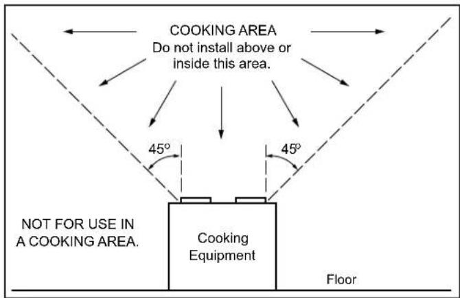
- For general ventilating use only. Do not use to exhaust hazardous or explosive materials and vapors.
- Install the fan at least 8 feet (2.4 m) above the floor.
- To avoid motor bearing damage and noisy and/or unbalanced impellers, keep drywall spray, construction dust, etc. off power unit.
- DO NOT TOUCH THE HUMIDITY-SENSING CIRCUIT BOARD. Electrostatic discharge may damage the circuit board.
- Please read specification label on product for further information and requirements.
CLEANING & MAINTENANCE
TO CLEAN THE GRILLE: Remove the grille and grille trim. Plastic parts can be cleaned with mild detergent, such as dishwashing liquid. Dry with a soft cloth. DO NOT USE ABRASIVE CLOTH, STEEL WOOL PADS OR SCOURING POWDERS.
TO CLEAN INTERIOR OF THE UNIT: Once the grille and grille trim are removed, gently vacuum interior of the unit with the dusting brush attachment.
For Warranty Statement, Service Parts, Technical Support, or to Register your product, please visit our website or call: In the United States - Broan-NuTone.com 800-558-1711. In Canada - Broan-NuTone.ca 800-567-3855.
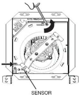
TO CLEAN THE SENSOR: Remove the grille and grille trim. Use a dry dustcloth, clean toothbrush or lightly vacuum to clean sensor and grille. DO NOT USE ABRASIVE CLOTH, STEEL WOOL PADS OR SCOURING POWDERS. DO NOT USE cleaning sprays, solvents or water on or near sensor!
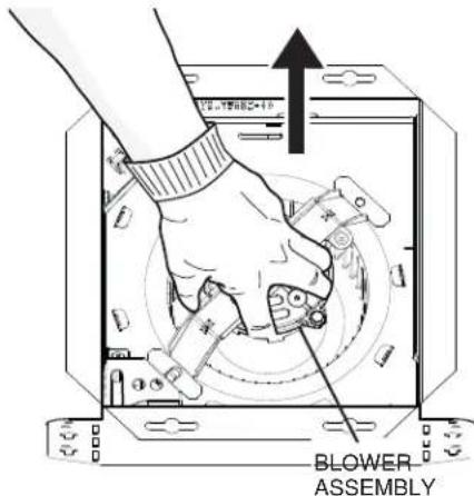
The motor is permanently lubricated and never needs oiling. If the motor bearings are making excessive or unusual noises, replace the blower assembly (includes motor and impeller).
OPERATION
Use an on/off switch to operate the fan, light and sensor. The fan, light and sensor can be operated separately if an appropriate 3-function wall control is used.
Refer to Broan-NuTone catalog for a complete line of accessories/controls to effectively adapt these fans to your requirements.
SENSOR OPERATION
To activate the humidity sensor, turn the humidity switch ON. The fan will run automatically when the set Humidity condition is met, and stop automatically when the timer condition is met. The Humidity Sensor may occasionally turn the fan ON when environmental conditions change.
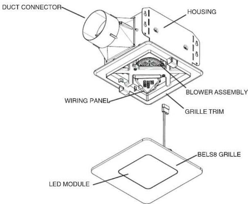
natural_image
Technical line drawing of a mechanical assembly with labeled components (no readable text or symbols)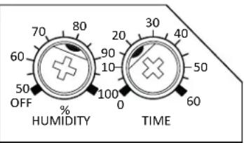
% HUMIDITY ADJUSTMENT
To adjust the % HUMIDITY:
- Turn power off at electrical service panel.
- Use a small screwdriver to carefully rotate %HUMIDITY control to desired level. If fan is not responding to changing humidity conditions, adjust towards 50%. If fan is responding too often to changing humidity conditions, adjust towards 100%.
- Turn power on.
- Repeat above steps if necessary.
MINUTES ADJUSTMENT (TIMER)
This humidity-sensing fan has a timer that controls how long the fan remains on after the humidity in the room returns to the user-adjustable set-point.
To adjust the timer:
- Disconnect power at electrical service panel.
- Use a small screwdriver to carefully rotate MINUTES control to increase or decrease time.
- Turn power on.
- Repeat above steps if necessary.
If fan is still not responding as desired after making adjustments, contact Broan Technical Support.
MANUAL ON
To manually energize the fan:
- Turn the fan only switch on
or - Cycle the Humidity switch on/off/on.
IMPORTANT - The ducting from this fan to the outside of the building has a strong effect on the air flow, noise and energy use of the fan. Use the shortest, straightest duct routing possible for best performance, and avoid installing the fan with smaller ducts than recommended. Insulation around the ducts can reduce energy loss and inhibit mold growth. Fans installed with existing ducts may not achieve their rated airflow.

OPTION - To mount housing anywhere between ceiling framing: Use optional Hanger Bar Kit (sold separately from local distributors or website). Follow mounting instructions included with kit.
QUICK START GUIDE
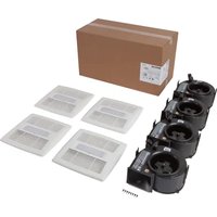
Remove from packaging. Remove blower assembly and wiring panel.
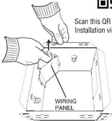

Scan this QR code for Installation video.
2 Mount housing. Choose one option to mount housing to ceiling structure:
New Construction Retrofit
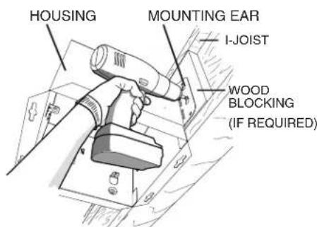
Other options:
- Hanger bars (sold separately Model Number MHB4)
- Flange Install (see Installation video)
Note: If you are installing retrofit, bend the ears in and use the mask from packaging to cut opening to correct size.
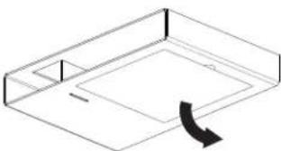
natural_image
Isometric line drawing of a rectangular box with a curved arrow indicating rotation or movement (no text or symbols)or
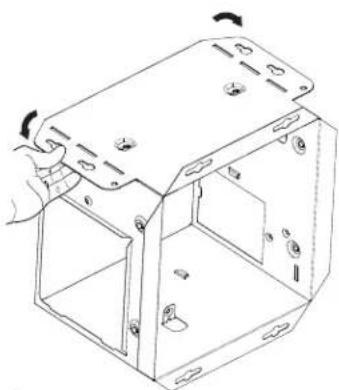
natural_image
Technical line drawing of a mechanical housing or enclosure with mounting holes and internal compartments (no text or symbols)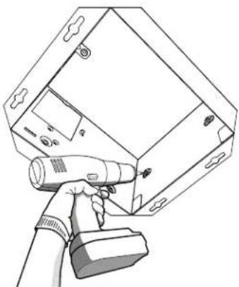
natural_image
Line drawing of a handheld device with a handheld probe, mounted on a rectangular device (no text or symbols visible)3
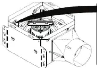
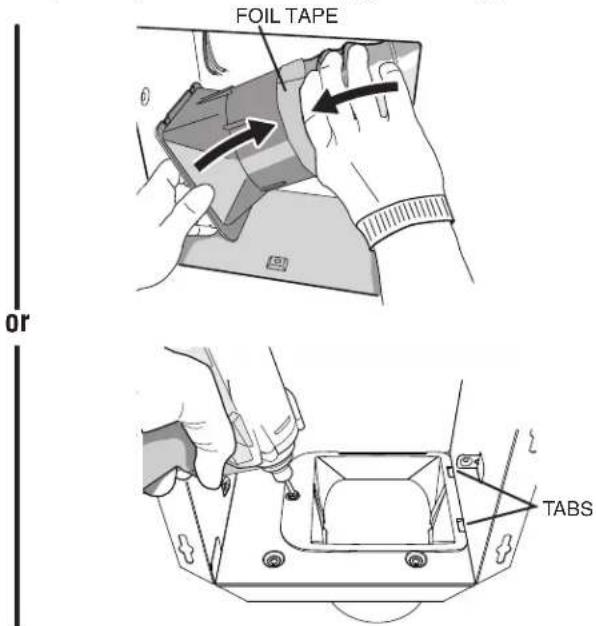
Choose one option to attach duct connector.
New Construction Retrofit
Install duct connector (use screw from parts bag and ensure tabs engage in housing), then attach new construction ductwork with foil tape.
Pull ductwork into housing and attach to duct connector with foil tape, then install duct connector (use screw from parts bag and ensure tabs engage in housing).
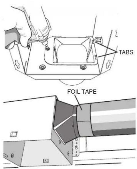
Pro Tip: First and last 18" of the ducting should be rigid or stretched straight for expected performance.
4
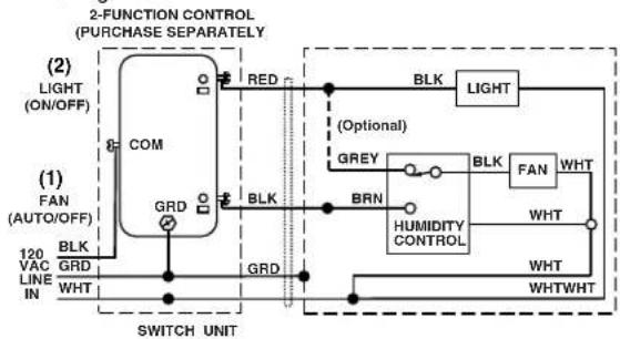
Connect wiring.
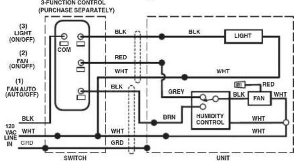
WIRING OPTION # 1
- When first switch (1) is ON, fan will operate automatically based on room humidity conditions.
- Turn fan ON immediately for the set timer period (to control odors), by cycling first switch (1) ON/OFF/ON.
- Use second switch (2) to turn light ON/OFF.
- With optional connection shown, fan will always be ON when light is ON.
flowchart
graph TD
    A["2-FUNCTION CONTROL (PURCHASE SEPARATELY)"] --> B["(1) FAN (AUTO/OFF)"]
    B --> C["COM"]
    C --> D["RED"]
    D --> E["BLK"]
    E --> F["LIGHT"]
    F --> G["BRN"]
    G --> H["HUMIDITY CONTROL"]
    H --> I["WHT"]
    I --> J["WHTWHT"]
    J --> K["WHT"]
    K --> L["SWITCH UNIT"]
    M["120 VAC LINE IN"] --> N["BLK GRD WHT"]
    N --> O["GRD"]
    O --> P["BRN"]
    P --> Q["GREY"]
    Q --> R["BLK"]
    R --> S["FAN WHT"]
    S --> T["BRN"]
    T --> U["HUMIDITY CONTROL"]
    U --> V["WHT"]
    V --> W["WHTWHT"]
    X["SWITCH UNIT"] --> Y["BRN"]
    Y --> Z["GREY"]
    Z --> AA["BLK"]
    AA --> AB["FAN WHT"]
    AB --> AC["BRN"]
    AC --> AD["HUMIDITY CONTROL"]
    AD --> AE["WHT"]
    AE --> AF["WHTWHT"]
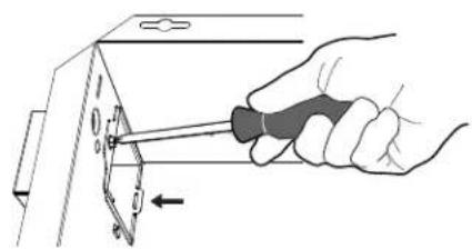
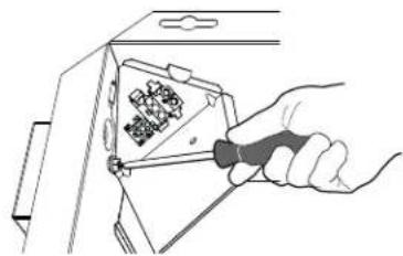
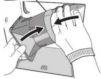
5
Attach wire enclosure by tab and screw.
natural_image
Hand using a screwdriver to adjust or install a component on a metal bracket (no text or symbols visible)Scan this QR code for helpful hints.

WIRING OPTION # 2
- When first switch (1) is ON, fan will operate automatically based on room humidity conditions.
- Turn fan ON immediately (to control odors), by using second switch (2).
- Use third switch (3) to turn light ON/OFF.
flowchart
graph TD
    A["3-FUNCTION CONTROL (PURCHASE SEPARATELY)"] --> B["(1) FAN AUTO (AUTO/OFF)"]
    A --> C["(2) FAN (ON/OFF)"]
    A --> D["(3) LIGHT (ON/OFF)"]
    B --> E["BRN"]
    C --> F["BRN"]
    D --> G["BRN"]
    E --> H["WHT"]
    F --> I["WHT"]
    G --> J["WHT"]
    H --> K["SWITCH"]
    I --> L["UNIT"]
    J --> M["UNIT"]
    N["COM"] --> O["BLK"]
    P["RED"] --> Q["WHT"]
    R["BRN"] --> S["HUMIDITY CONTROL"]
    T["GRD"] --> U["UNIT"]
    V["BRN"] --> W["WHT"]
    X["BRN"] --> Y["WHT"]
    Z["BRN"] --> AA["WHT"]
    AB["BRN"] --> AC["WHT"]
    AD["BRN"] --> AE["WHT"]
    AF["BRN"] --> AG["WHT"]
    AH["BRN"] --> AI["WHT"]
    AJ["BRN"] --> AK["WHT"]
    AL["BRN"] --> AM["WHT"]
    AN["BRN"] --> AO["WHT"]
    AP["BRN"] --> AQ["WHT"]
    AR["BRN"] --> AS["WHT"]
    AT["BRN"] --> AU["WHT"]
    AV["BRN"] --> AW["WHT"]
    AX["BRN"] --> AY["WHT"]
    AZ["BRN"] --> BA["WHT"]
    BB["BRN"] --> BC["WHT"]
    BD["BRN"] --> BE["WHT"]
    BF["BRN"] --> BG["WHT"]
    BH["BRN"] --> BI["WHT"]
    BJ["BRN"] --> BK["WHT"]
    BL["BRN"] --> BLW["BRN"]
    BN["LIGHT"] --> BO["WHT"]
    BP["RED"] --> BRW["WHT"]
    BS["HUMIDITY CONTROL"] --> BT["WHT"]
    BU["FAN"] --> BV["WHT"]
    BW["BRN"] --> BX["WHT"]
    BY["WHT"] --> BZ["WHT"]
6
Re-install wiring panel and secure with screw from parts bag.
natural_image
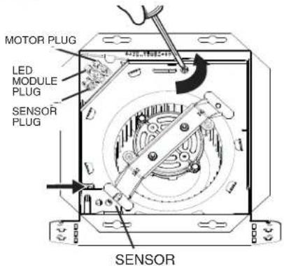
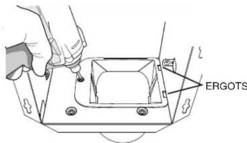
Hand using a screwdriver to adjust a component with a grid of small components (no text or symbols visible)7 Install the blower assembly and sensor with provided screws. Plug in blower. Plug in sensor. Note: For new construction, use mask to protect blower until ceiling is finished.
natural_image
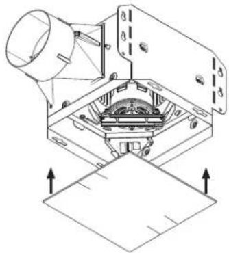
Technical diagram of a mechanical assembly with no visible text or symbols8 Install the grille trim with screws from parts bag.
9 Plug in LED module.
10 Install the grille by sliding clips into grille trim.
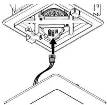
natural_image
Diagram of a device with an attached cable and connector, showing internal components without any text or symbols.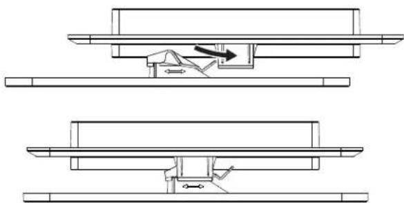
natural_image
Technical line drawing showing two mechanical assembly steps with no visible text or symbolsNote: Depending upon model, your grille may look different.
natural_image
Technical diagram of a mechanical assembly with labeled components (no readable text or symbols)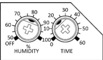
RÉGLAGE DU % D'HUMIDITÉ
natural_image
Technical line drawing of a metal enclosure with mounting holes and internal compartments (no text or symbols)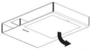
natural_image
Isometric line drawing of a rectangular frame with a curved arrow indicating rotation (no text or symbols)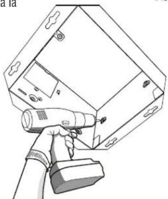
natural_image
Line drawing of a handheld device with a handheld tool, mounted on a rectangular device (no text or symbols visible)3
natural_image
Diagram of a mechanical assembly with no visible text or symbolsRUBAN D'ALUMINIUM
natural_image
Illustration of hands holding a device with directional arrows indicating movement (no text or symbols)ou
natural_image
Hand using a screwdriver to adjust or install a component on a metal bracket (no text or symbols visible)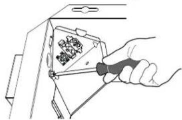
natural_image
Hand using a tool to adjust or install a component with a grid of pins (no text or symbols visible)
7
natural_image
Technical line drawing of a mechanical assembly with no visible text or symbols8
natural_image
Diagram of a device with an attached cable and connector, showing internal components without any text or symbols.10